manuals.online logo
Brands
  1. Home
  2. •
  3. Brands
  4. •
  5. Sanyo
  6. •
  7. Microwave Oven
  8. •
  9. Sanyo EM-X600S User manual

Sanyo EM-X600S User manual

FILE NO.
SUPPLEMENTOF
SERVICE MANUAL Microwave Oven EM-)(600s (New.zealand)
/
—-------
I)[RI. (” T,4(’[’I..S.Y
Product Code No. 43731475
See the service manual of EM-N102WS(SM-86 OO78)
Foreword except the items described in this service manual.
Read this manual carefully, especially precaution on microwave energy, and follow the procedure strictly.
Careless servicing and testing may expose yourself to the microwave energy leakage. $
1
IPRECAUTIONS
PRECAUTIONS TO BE OBSERVED BEFORE AND DURING SERVICING TO AVOID POSSIBLE EXPOSURE TO
EXCESSIVE MICROWAVE ENERGY
(a)
(b)
(c)
(d)
Do not operate or allow the oven to be operated with the door open.
Make the following safety checks on all ovens to be serviced before activating the magnetron or other microwave
source, and make repairs as necessary:
(1) Interlock operation, (2) proper door closing, (3) seal and sealing surfaces (arcing, wear, and other damage),
(4) damage to or loosening of hinges and latches, (5) evidence of dropping or abuse.
Before turning on microwave power for any service test or inspection within the microwave generating compaflments,
check the magnetron, wave guide or transmission line, and cavity for proper alignment, integrity, and connections.
Any defective or misadjusted components in the interlock, monitor, door seal, and microwave generation and transmis-
sion systems shall be repaired, replaced, or adjusted by procedures described in this manual before the oven is
released to the owner.
REFERENCE NO. SS-860128
—TABLE OF CONTENTS —
Specifications . . . . . . . . . . . . . . . . . . . . . . . . . . . . . . . . . . ...1 Test Procedures . . . . . . . . . . . ..3
Power Output Measurement . . .1 Disassembly Instructions .... ...4
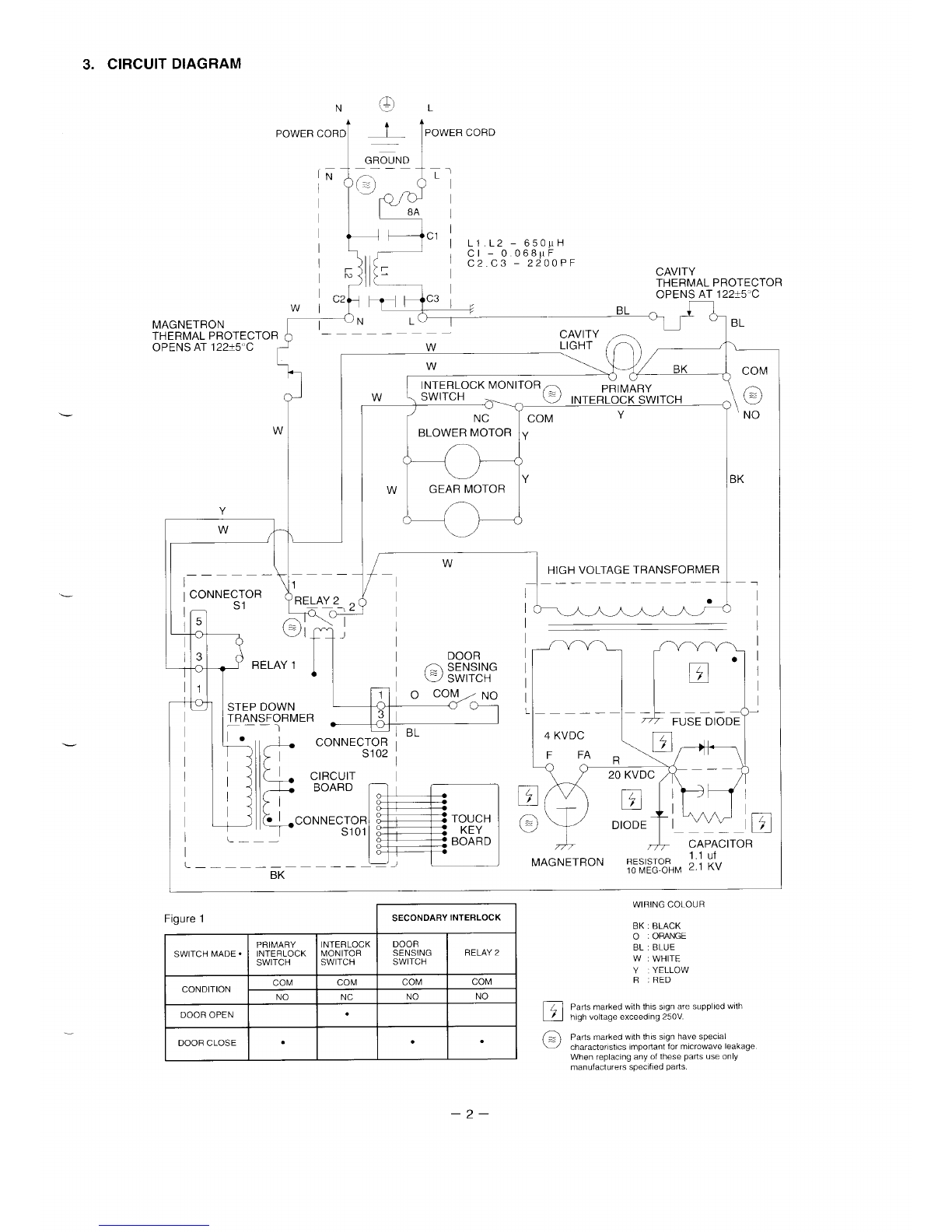
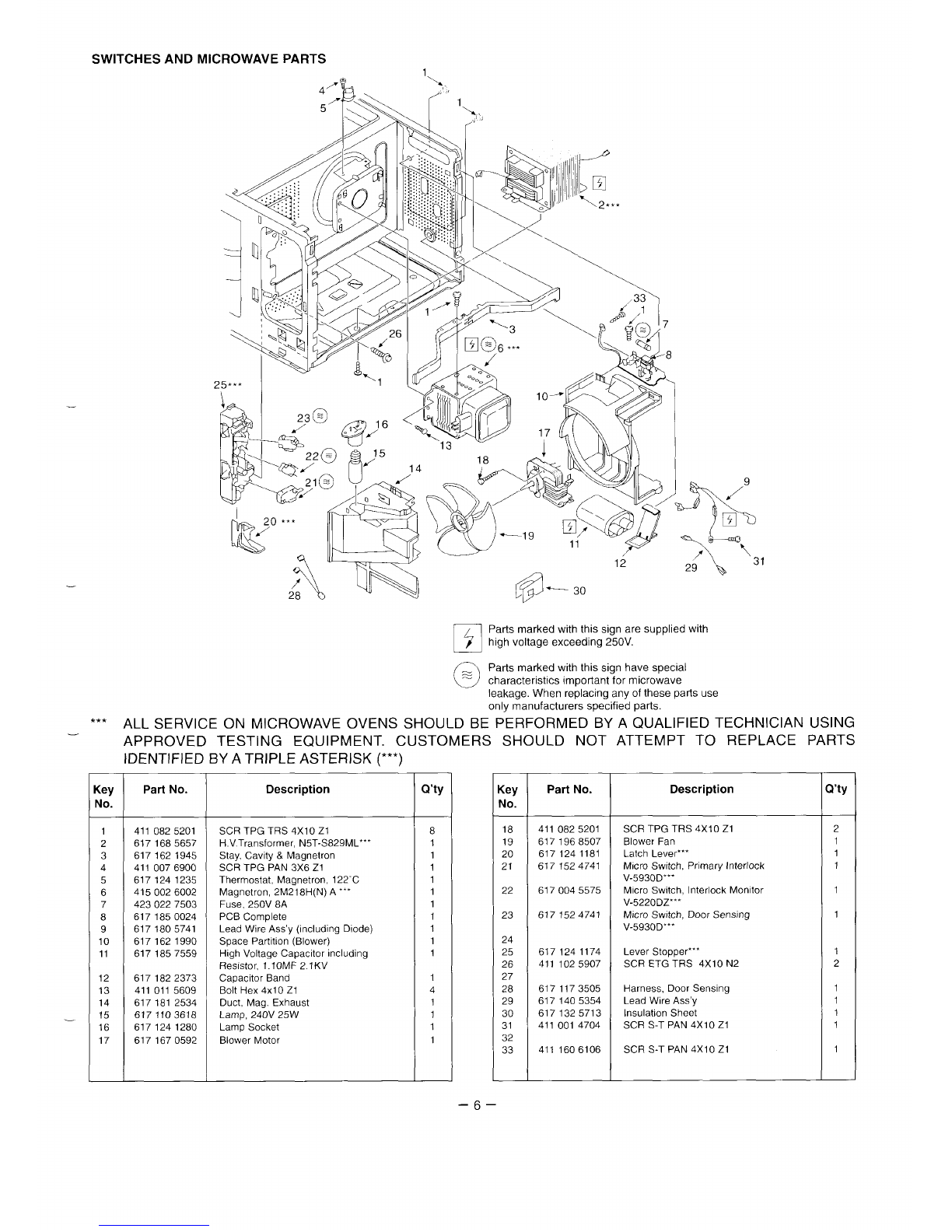
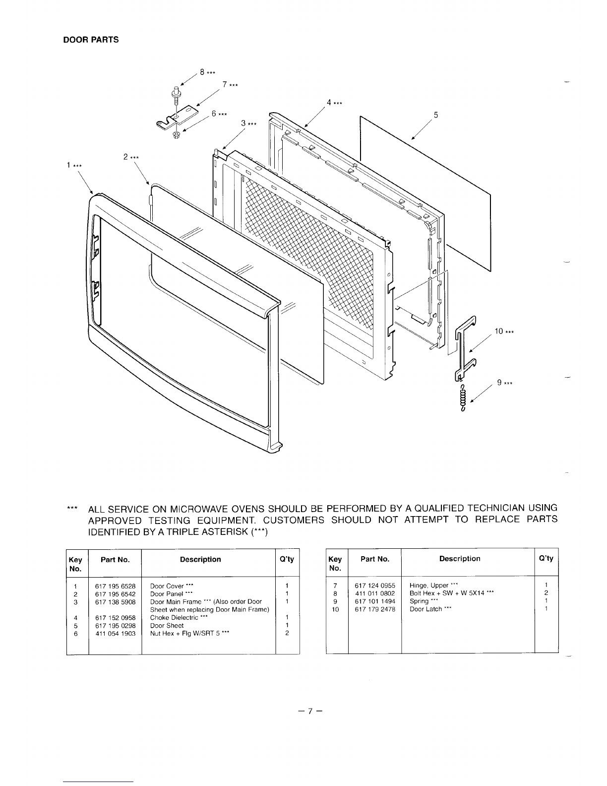
Circuit Diagram ....................................2 Exploded View and Parts List.. .....................5-10 –
Overall Circuit Diagram .....11
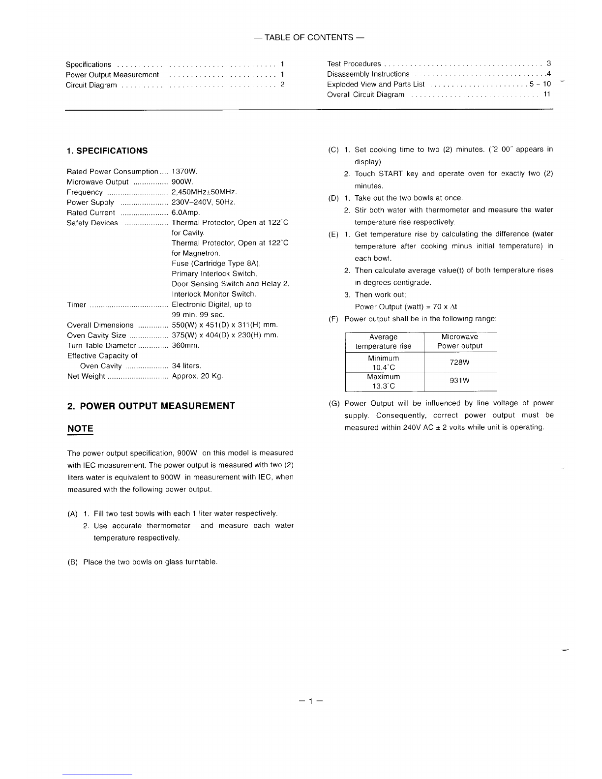
l. SPECIFICATIONS
Rated Power Consumption
Microwave Output
Frequency
Power Supply
Rated Current
Safety Devices
Timer
Overall Dimensions
Oven Cavity Size
Turn Table Diameter
Effective Capacity of
Oven Cavity
Net Weight
2. POWER OUTPUT
NOTE
(c)
1370W,
900W.
2,450MHz&50MHz.
230V–240V, 50Hz. (D)
6.OAmp.
Thermal Protector, Open at 122°C
for Cavity. (E)
Thermal Protector, Open at 122°C
for Magnetron.
Fuse (Cartridge Type 8A),
Primary Interlock Switch,
Door Sensing Switch and Relay2,
Interlock Monitor Switch.
Electronic Digital, up to
99 min. 99 sec.
550(W) x451(D) x311(H) mm. (F)
375(W) X404(D) x230(H) mm.
360mm.
34 liters.
Approx.20 Kg.
MEASUREMENT (G)
Thepower output specification, 900W on this model is measured
with IEC measurement. Thepower output ismeasured with two(2)
liters water is equivalent to900W in measurement with lEC, when
measured with the following power output.
(A) 1. Fill twotest bowls with eachl Iiter water respectively.
2. Use accurate thermometer and measure each water
temperature respectively.
(B) Place thetwobowls on glass turntable.
1.
2.
1.
2.
1.
2.
3.
Set cooking time to two (2) minutes. (“2 00” appears in
display)
Touch START key and operate oven for exactly two (2)
minutes.
Take out the two bowls at once.
Stir both water with thermometer and measure the water
temperature rise respectively.
Get temperature rise by calculating the difference (water
temperature after cooking minus initial temperature) in
each bowl.
Then calculate average value(t) of both temperature rises
mdegrees centigrade.
Then workout;
Power Output (watt) =70 xAt
Power output shall be in the following range:
Average Microwave
temperature rise Power output
Minimum
10.4”C 728W
Maximum 931W
13.3°C
Power Output will be influenced by line voltage of power
supply. Consequently, correct power output must be
measured within 240VAC +2 volts while unit is operating.
–l–
3. CIRCUIT DIAGRAM
II
1$5:
c’ \L1. L2-650y H
I::-c: !’6;)oFOp F
~
LCAVITY
THERMAL PROTECTOR
~N7 ,,Lf3 ~, ,, OPENSAT122+5C
—. CAVITY
wLIGHT ~,—
w
MAGNETRON
THERMAL PROTECTOR
OPENSAT 122f5<C J
LwBK COM
,@
NO
IK
—
7
[WY? ‘NTEti@’Tc’
wIBLOWER MOTOR Iy
P?Y
wGEAR MOTOR
o4
YJ
k[-1 wHIGH VOLTAGE TRANSFORMER
IL
1
1CONNE\~OR RELAY2 z
$F$ Q
15 El T
13 RELAY 1
II
a
1
STEP DOWN
TRANSFORMER 3
——— 1
I
I
J-
❑’
FUSE—Dl~DE
II
—
IBL
L— F~Ej
CIRCUIT
BOARD
cICONNECTOR
Slol
.1
TOUCH
KEY
BOARD
L
WIRINGCOLOUR
BK BLACK
o.ORANGE
BL BLUE
WwHITE
YYELLOW
RRED
Parts marked w!th th[s sign are supplled with
high voltage exceeding 250V
Parts marked with this sign have special
characteristics Impoflant formlcmwave leakage
When replacing any of these park use only
manufacturers speclf[ed paris
Figure 1ISECONDARYINTERLOCK I
PRIMARY INTERLOCK DOOR
SWITCH MADE. INTERLOCK MONITOR SENSING
SWITCH RELAY 2
SWITCH SWITCH
CONDITION COM COM COM COM
NO NC NO NO
DOOR OPEN .
DOOR CLOSE ●..
–2–
4. TEST PROCEDURES
—
—
–3–
5. DISASSEMBLY INSTRUCTIONS
A. REMOVING BLOWER MOTOR
(Figures 3(Top View) and 4)
(1)Remove screw securing the stay.
(2) Disconnect all lead wires from the blower motor
and H.V. capacitor.
(3) Remove 2screws securing the blower base and
disengage 3hooks from the rear plate of cavity
(Figure 4)
(4) Remove 1screw securing the blower motor with
the blower base.
B. REMOVING MAGNETRON
(Figure 3(Top View))
After removing the blower motor:
(1) Remove duct (msg. intake) and duct (msg.
-exhaust).
(2) Remove 1screw securing the thermal protector.
(3) Disconnect 2lead wires from the magnetron.
(4) Remove 4screws securing the magnetron to the
waveguide.
(5) Take out magnetron VERY CAREFULLY.
NOTES
1. When removing the magnetron from the cavity or
Lwave guide, use aproper care so that the dome of
the magnetron does not hit any adjacent parts of
microwave oven.
2. Make sure that the contact face of the magnetron
gasket is free from any damage or deformation.
3. Adjust the position of the magnetron properly, so
that it correctly sits in place and the magnetron
gasket is in contact with the mounting rim evenly.
L. 4. While holding the magnetron under this condition,
tighten mounting screws or nuts with your fingers
temporarily.
5. Further tighten the screws or nuts with abox
wrench, giving one or two turns to each of the
screws (or nuts) alternatively so that the magnetron
is mounted on to the bracket uniformly.
6. After replacing the magnetron, be sure to check the
microwave energy leakage with aleakage detector
and confirm the leakage is below 5mW/cmZ.
NOTES
When inserting duct (msg. exhaust), overlap the lower
tab of the duct onto the magnetron, at the same time
-. ensure the hook on the duct is properly engage to the
magnetron (See figure 5).
Blower base
Duct (msg. exhaust) \
Figure 3(Top View)
—
Blower Motor ~Y Screws
Figure 4
Screws Upper Hook
,A, ~~~~ Magnetron
‘rF3f
0° /
Duct
(mag exhaust) .’
A
Lower Tab
Overlap onto
magnetron
,–
Figure 5
–4–
6. EXPLODED VIEW AND PART LIST
CAVITY PARTS
17
15’ &/
if
2
*** ALL SERVICE ON MICROWAVE OVENS SHOULD BE PERFORMED BY A QUALIFIED TECHNICIAN USING
APPROVED TESTING EQUIPMENT. CUSTOMERS SHOULD NOT ATTEMPT TO REPLACE PARTS
IDENTIFIED BY A TRIPLE ASTERISK (***)
[eyPart No. Description Q’ty
do.
1 6171862089 Cabinet (Also order circuit diagram 1
when replaclng Cabinet)
2 4110825201 SCR TPG TRS 4X1O ZI 8
3411 1606007 SCR TPG TRS +SRT 4X10mm 4
4 6171385113 Power Cord 1
5
6 6171888089 Oven Cavity ‘“ (Not Service Parts) 1
76171512458 Gear Motor 1
84110105808 SCR EVR PAN 4X1O ZI 2
9 6171815986 Bottom Plate ‘“ (Not Service Parts) 1
10 6171445435 Plastlc Foot with Canoe Clip 4
11 4110110802 Bolt Hex +SW +W5X14mm Z1 ““ 2
leyPart No. Description Q’ty
40.
12 6171240795 Hinge, Lower ““ 1
13 4110892500 Washer F5xIOX0.8 1
14 6171208481 Insulation Sheet 1
15 6171444476 Turn Table Shaft 1
16 6171872026 Roller 1
17 6171893816 Rotating Tray 1
18 6171812503 Antenna 1
19 6171621938 Cavity Cover 1
20 4110691707 SCR TPG TRS 4X6 DA 1
21 4110076900 SCR TPG PAN 3X6 ZI 1
22 6171241235 Thermostat, Cavity 122°C 1
23 6170805315 Special Washer 1
24 411 1606106 SCR S-T PAN 4X1O ZI 2
–5–
SWITCHES AND MICROWAVE PARTS 4
—
—
BParts marked with this sign are supplied with
high voltage exceeding 250V.
oParts marked with this sign have special
~characteristics important for microwave
leakage. When replacing any of these parts use
only manufacturers specified parts.
*** ALL SERVICE ON MICROWAVE OVENS SHOULD BE PERFORMED BY A QUALIFIED TECHNICIAN USING
<ey
No.
1
2
3
4
5
6
7
8
9
10
11
12
13
14
15
16
17
APPROVED TESTING EQUIPMENT. CUSTOMERS SHOULD NOT ATTEMPT TO REPLACE PARTS
IDENTIFIED BY A TRIPLE ASTERISK (**’)
Part No.
4110825201
6171685657
6171621945
4110076900
6171241235
4150026002
4230227503
6171850024
6171805741
6171621990
6171857559
6171822373
4110115609
6171812534
6171103618
6171241280
6171670592
Description
SCR TPG TRS 4X1O ZI
H.V.Transformer, N5T-S829ML””
Stay, Cavity &Magnetron
SCR TPG PAN 3X6 Z1
Thermostat, Magnetron, 122°C
Magnetron, 2M218H(N) A‘“
Fuse, 250V 8A
PCB Complete
Lead Wire Ass’y (Including Diode)
Space Partition (Blower)
High Voltage Capacitor including
Resrstor, I. IOMF 2IKV
Capacitor Band
Bolt Hex 4x1O Z1
Duct, Msg. Exhaust
Lamp, 240V 25W
Lamp Socket
Blower Motor
Q’ty
8
1
1
1
1
1
1
1
1
1
1
i
4
1
1
1
1
:ey Part No. Description Q’ty
40.
18 4110825201 SCR TPG TRS 4XI0 Z1 2
19 6171968507 Blower Fan 1
20 6171241181 Latch Lever’” 1
21 6171524741 Micro Swtch, Primary Interlock 1
V-5930D””’
22 6170045575 Micro Switch, Interlock Monitor 1
V-5220D7°
23 6171524741 Micro Swkch, Door Sensing 1
V-5930D’””
24
25 6171241174 Lever Stopper’” 1
26 411 1025907 SCR ETG TRS 4X1O N2 2
27
28 6171173505 Harness, Door Sensing 1
’29 6171405354 Lead Wire Ass’y 1
30 6171325713 Insulation Sheet 1
31 4110014704 SCR S-T PAN 4X1O ZI 1
32
33 411 1606106 SCR S-T PAN 4XI0 Z1 1
-6-
DOOR PARTS
/8 **’
\
10 ***
9***
*** ALL SERVICE ON MICROWAVE OVENS SHOULD BE PERFORMED BY A QUALIFIED TECHNICIAN USING
APPROVED TESTING EQUIPMENT. CUSTOMERS SHOULD NOT ATTEMPT TO REPLACE PARTS
IDENTIFIED BY A TRIPLE ASTERISK (***)
[eyPert No. Description Q’ty
do.
1 6171956528 Door Cover ‘“ 1
2 6171956542 Door Panel ‘“ 1
36171385908 Door Main Frame ‘“ (Also order Door 1
Sheet when replaclng Door Main Frame)
46171520958 Choke Dielectric ‘“ 1
5 6171950298 Door Sheet 1
6 4110541903 Nut Hex +Flg W/SRT 5‘“ 2
(ey Part No. Description Q’ty
Yo.
7 6171240955 Hinge, Upper ““ 1
84110110802 Bolt Hex +SW +W5X14 ‘“ 2
9617101 1494 Spring ‘“ 1
10 6171792478 Door Latch ‘“ 1
–7–
CONTROL PANEL PARTS
2***
r. \
1***
\
6
3\7***
*** ALL SERVICE ON MICROWAVE OVENS SHOULD BE PERFORMED BY A QUALIFIED TECHNICIAN USING
APPROVED TESTING EQUIPMENT. CUSTOMERS SHOULD NOT ATTEMPT TO REPLACE PARTS
IDENTIFIED BY A TRIPLE ASTERISK (***)
<ey
No.
1
2
3
4
5
6
<ey
No.
Part No.
6171937022
6171521047
6171514346
6171521030
6171514377
411 1606205
Part No.
Description
Control Sheet ‘“ (Also order Touch Key
Board when replacing Control Sheet)
Touch Key Board ‘“ (Also order Control
Sheet when replacing Touch Key Board)
Control Plate
Control Frame ““
Control Base ‘“
SCR TPG TRS 4X1O Z1
PRINTED MATTER (Items Not Illustrated)
—6171987324
6171937541
6171937121
6172000916
6171891850
Description
Cook Book
Instructions Manual
Carton Box
Name Plate
Circuit Diagram
Q’ty
1
1
1
1
1
1
~
Q’ty
1
1
1
1
1
–8–
(ey
Uo.
7
8
9
10
Part No.
6171837681
411 1295805
6170809559
6171514339
Description
Control Circu!t Board Complete ‘“
SCR TPG BIN 3XI0 Z1
Spring, Door Release Lever ‘“’
Door Release Lever ‘“
Q’ty
1
2
1
1
CONTROL CIRCUIT BOARD
(Part No. 617183 7681)
2~’
D109 Kl- DT1 @c 4594 V-0 o
D108 Kl-
D107 W- ;
%Ul
D11O td-
Dlll ld- 4B
r
~yo
Ah&
R133 ~s
~R134 Icll
MA/ R135 Pm
J71R56. o
wR136
1~lol
R109
;3 ~R137 MR~. .
—+1—~.
I II ~~(R132)
??\ m(R131)RI14 I I /Ylo2~ \“7
\r
l— —,-,~
r
llW +‘Dll
~c’06
1L, d
c
I1- 1I
A’ w
TP-2
TP-5
TP-4
TP-I
TP-3
—.
–9–
CONTROL CIRCUIT BOARD
(Part No. 617183 7681)
—
.
Key No. IOrder Part No Descrlptlon Q’fy
NTEGRATED CIRCUIT
cl 14093789804 IIC LM 8756 -B60S I1
rRANSISTORS
2102, Q103 4050005612 DTC143XS-TP 2
2105 4050800217 DTC123YS.TP 1
211 4050354819 2SC1685-Q-TP 1
2104 4050043010 2SA564A-Q-TP 1
2101 4050824619 DTA123YS.TP 1
310DES
[Dll 4070570510 RD5.6ESB3 1
ZD12 4070789031 RD16ESB3-TP 1
ZD101 4070559010 RD3.9ESB2 1
111, D12 4070120220 IN4002-TP 2
2101-111 4070124317 ISS132-TP 11
2APACITORS
211 4031527218 Electrolytic, 1000mfd, 1
+-20% 25V
212 4031527327 Electrolytic, 100mfd, 1
+-20”/0, 35V
C13 4031478629 Electrolytic, 47mfd, 1
+-20% 10V
C102 4031478837 Electrolytic, lmfd, 1
+-20”/., 50V
C104 4030024728 Electrolytic, O1mfd, 1
+-5°/0>25V
Clol, 103, 4031425326 Ceramic, 0.01 mfd 4
105-106 +-5% 50V
Key No Order Pari No. Description IQty
3ESISTORS
3102
?14, 103, 107
110
3104>108, 114
117-121
<122
3109
312, 13
315
RI15, 116
RI12
Rlll
Rll, 106, 113
133-137
R105
RIO1
RESISTORS B
RB101
MISCELLANEC
BZ1
DT1
RLI
RL2
RSI
S1
Slol
SI02
VST1
PT1
JBI
2
Jl, 4, 6, 7,
3, 10
J101-104
4010124434
4010125639
4010126953
4010128056
4010129231
4010162555
4010163750
4010169653
4010182751
401 0183738
4010201957
4010202835
4010231637
;KS I
6170103541
>
4200006800
6171853735
6171379358
6171410549
6171283372
6171694109
6171245059
617111 1392
4071185505
6171712155
6171325744
6170794107
6170794299
6170794237
Carbon, 100 ohms
+- 5% I14W
Carbon, 1Kohms
+- 5%, I14W
Carbon, IOK ohms
+-5%, 114W
Carbon, 100K ohms
+-5% 114VV
Carbon, 1Mohms
+-5”/0, I14VV
Carbon, 220 ohms
+-5%, 114W
Carbon, 22K ohms
+-5%, 114W
Carbon, 27 ohms
+-5%, 114W
Carbon, 330 ohms
+-5% 114W
Carbon, 3.3K ohms
+-5%, 114bV
Carbon, 4.7K ohms
+-5%, I14W
Carbon, 47K ohms
+-5%, 114W
Carbon, 820 ohms
+-570, l/4w
1
4
8
1
1
2
1
2
1
1
8
1
1
100K ohms, +-1OO/.,
5-Pc, 118W
Buzzer PKM22EPT-
2001
Display Tube
Relay, OJE-SH-I12LM
Relay, DEC DU12D1-IPR
Ceramtc Resonator,
CST4.00MGW
Connector
Connector, 10P Male
Connector, 2/3P, Male
Varistor ENC471 D-1OA
Step-down Transformer,
PD5TK-S150
Noise Filter
Spacer, Display Tube
Jumper
Jumper
1
1
1
1
1
1
1
1
1
1
1
1
1
6
4
–lo–
,_ ————— ——— —–.––––___–_ __
I
I,.,
..,-, .& I.< I
I
I
I
l___
I
==&=+&
—
I,--,
wI1E
——— L–––I–––L ———.
—
I
I
I
I
I
I
—
——— ————
L,.,
:
,.., 11
—III
II I ,,,, II
I,., I1II
3I__–––––_––––_ ___’
si4y/#ifM
-
SANYO Electric Co., Ltd.
Osaka, Japan
May ‘97/1 00 LT Printed in Singapore –11–

Other Sanyo Microwave Oven manuals

Sanyo EM-C1850 User manual

Sanyo

Sanyo EM-C1850 User manual

Sanyo EM-S2298V User manual

Sanyo

Sanyo EM-S2298V User manual

Sanyo EMS9515W - 1.4 Cubic Foot Capacity Countertop Microwave... User manual

Sanyo

Sanyo EMS9515W - 1.4 Cubic Foot Capacity Countertop Microwave... User manual

Sanyo EM-S889 User manual

Sanyo

Sanyo EM-S889 User manual

Sanyo EM-C8787B User manual

Sanyo

Sanyo EM-C8787B User manual

Sanyo EM-N107AS User manual

Sanyo

Sanyo EM-N107AS User manual

Sanyo EMS5595S - Microwave 0.9 Cubic Feet Use and care manual

Sanyo

Sanyo EMS5595S - Microwave 0.9 Cubic Feet Use and care manual

Sanyo EM-G430 User manual

Sanyo

Sanyo EM-G430 User manual

Sanyo EM870FS User manual

Sanyo

Sanyo EM870FS User manual

Sanyo EMO-SRT1(NX) User manual

Sanyo

Sanyo EMO-SRT1(NX) User manual

Sanyo EM-M105 User manual

Sanyo

Sanyo EM-M105 User manual

Sanyo EM-S355A User manual

Sanyo

Sanyo EM-S355A User manual

Sanyo EM-S7595S User manual

Sanyo

Sanyo EM-S7595S User manual

Sanyo EM-V890 User manual

Sanyo

Sanyo EM-V890 User manual

Sanyo EM-X400 User manual

Sanyo

Sanyo EM-X400 User manual

Sanyo EM-D9750ECO User manual

Sanyo

Sanyo EM-D9750ECO User manual

Sanyo EM-P410WS User manual

Sanyo

Sanyo EM-P410WS User manual

Sanyo EM-S100 Operating manual

Sanyo

Sanyo EM-S100 Operating manual

Sanyo EMC 1901 User manual

Sanyo

Sanyo EMC 1901 User manual

Sanyo EM-V860 User manual

Sanyo

Sanyo EM-V860 User manual

Sanyo EMS9515W - 1.4 Cubic Foot Capacity Countertop Microwave... Use and care manual

Sanyo

Sanyo EMS9515W - 1.4 Cubic Foot Capacity Countertop Microwave... Use and care manual

Sanyo Em-z2000s - 1000W 0.9 cu.ft. Mid-Size Microwave... User manual

Sanyo

Sanyo Em-z2000s - 1000W 0.9 cu.ft. Mid-Size Microwave... User manual

Sanyo EM-U1000W Use and care manual

Sanyo

Sanyo EM-U1000W Use and care manual

Sanyo EM-S8588V User manual

Sanyo

Sanyo EM-S8588V User manual

Popular Microwave Oven manuals by other brands

Samsung M1713 Owner's instructions

Samsung

Samsung M1713 Owner's instructions

Panasonic NN-GD462M operating instructions

Panasonic

Panasonic NN-GD462M operating instructions

Franklin Chef FCM7900 owner's manual

Franklin Chef

Franklin Chef FCM7900 owner's manual

Whirlpool AMW 523 Installation, quick start

Whirlpool

Whirlpool AMW 523 Installation, quick start

Panasonic Over The Range Microwave Oven Instalaltion guide

Panasonic

Panasonic Over The Range Microwave Oven Instalaltion guide

Danby DBMW0920BBB user manual

Danby

Danby DBMW0920BBB user manual

Whirlpool WOC75EC7HS quick start guide

Whirlpool

Whirlpool WOC75EC7HS quick start guide

WINIA KOS-61HB Service manual

WINIA

WINIA KOS-61HB Service manual

ACP MCS10DSE Quick start & reference guide

ACP

ACP MCS10DSE Quick start & reference guide

Beko MGF 28310 X user manual

Beko

Beko MGF 28310 X user manual

Aspes AMWC25900DGN instructions

Aspes

Aspes AMWC25900DGN instructions

LG LMV1976ST Owner's manual & cooking guide

LG

LG LMV1976ST Owner's manual & cooking guide

Defy 323 owner's manual

Defy

Defy 323 owner's manual

Baumatic B900SS-B instruction manual

Baumatic

Baumatic B900SS-B instruction manual

Bosch HMV 3051 U use and care manual

Bosch

Bosch HMV 3051 U use and care manual

Hansa AMG20BFH operating instructions

Hansa

Hansa AMG20BFH operating instructions

Hotpoint MP676IXH Daily reference guide

Hotpoint

Hotpoint MP676IXH Daily reference guide

AEG Micromat 328Z Instructions for use

AEG

AEG Micromat 328Z Instructions for use

manuals.online logo
manuals.online logoBrands
  • About & Mission
  • Contact us
  • Privacy Policy
  • Terms and Conditions

Copyright 2025 Manuals.Online. All Rights Reserved.