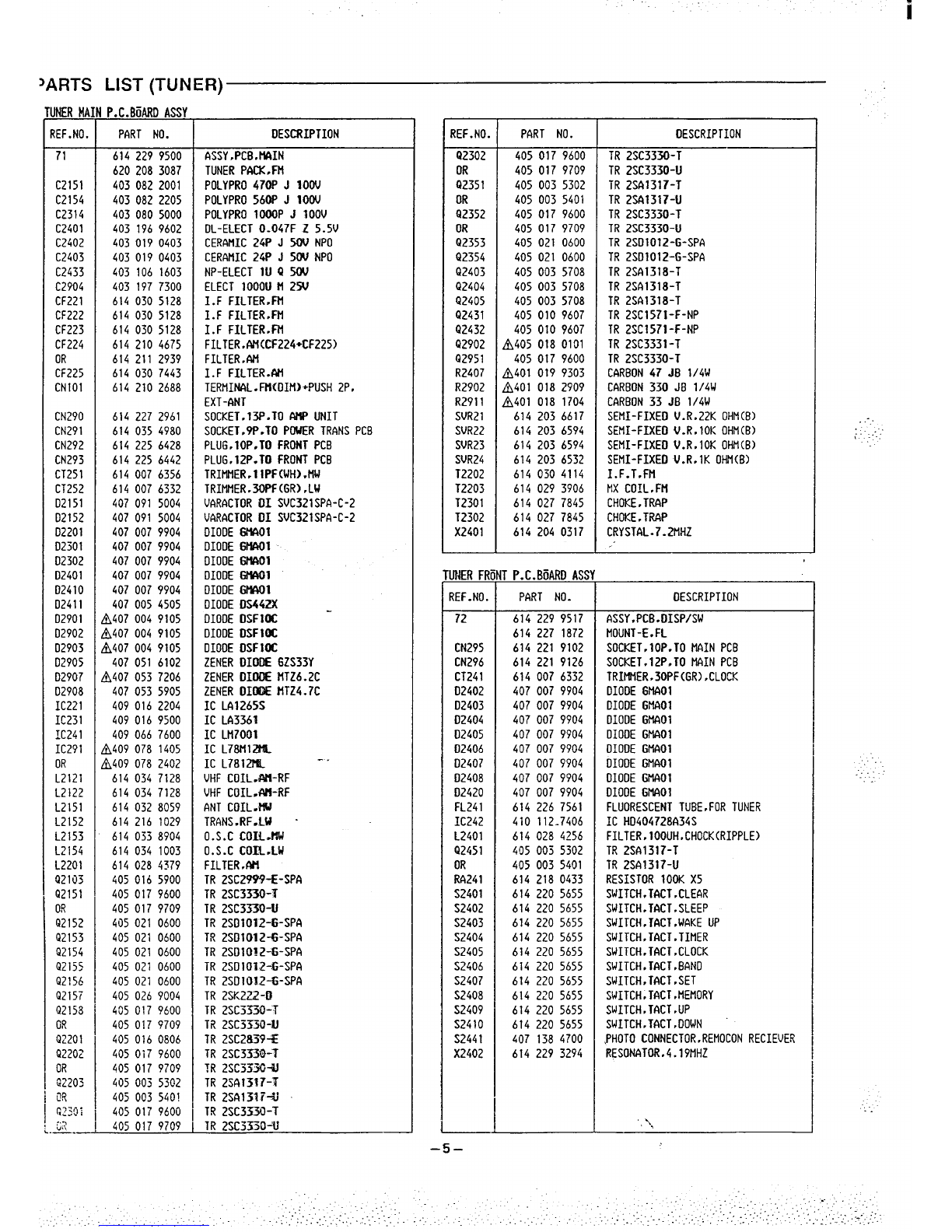
Sanyo DC-T44 User manual

Service Manual New Interior DC-T44 (NZ)
Component System
Contents
1.
2.
3.
4.
5.
5-1.
5-2.
5-3.
5-4.
5-5.
5-6.
6.
6-1.
6-2.
6-3.
6-4.
6-5.
6-6.
6-7.
6-8.
6-9.
6-10
SPECIFICATION . . . . . . . . . . . . . . . . . . . . . 1
SYSTEM CONNECTION . . . . . . . . . . . . . . 1
PARTS LIST(PACK &ACCESSORIES) . . 2
REMOTE CONTROLLER UNIT . . . . . . . . . 2
TUNER UNIT . . . . . . . . . . . . . . . . . . . . . . . 3
ADJUSTMENT . . . . . . . . . . . . . . . . . . . . . . 3
CABINET &CHASSIS EXPLODED VIEW 4
PARTS LIST . . . . . . . . . . . . . . . .. ... . . . . . . 4
IC BLOCK DIAGRAM . . . . . . . . . . . . . . . . 6
SCHEMATIC DIAGRAM . . . . . . . . . . . . . . . 8
WIRING DIAGRAM ................... 10
CD PLAYER UNIT . . . . . . . . . . . . . . . . . . . 13
LASER BEAM SAFETY PRECAUTION . . 13
CD MECHANISM REMOVAL . . . . . . . . . . 14
ADJUSTMENT . . . . . . . . . . . . . . . . . . . . . . 18
FLOWCHART ...................... 20
BLOCK DIAGRAM ................... 24
CABINET &CHASSIS EXPLODED VIEW 25
PARTS LIST . . . . . . . . . . . . . . . . . . . . . . . . 26
PARTS LIST(CD MECHANISM) . . . . . . . . 27
CD MECHANISM EXPLODED VIEW . . . . . 28
VOLTAGE TABLE . . . . . . . . . . . . . . . . . . . . 29
PRODUCT CODE No.
129 364 09
6-11. SCHEMATIC DIAGRAM . . . . . . . . . . . . . . . 30
6-12. WIRING DIAGRAM . . . . . . . . . . . . . . . . . . . 32
6-13. IC BLOCK DIAGRAM . . . . . . . . . . . . . . . . 34
7.
7-1.
7-2.
7-3.
7-4.
7-5.
7-6.
7-7.
7-8.
7-9.
TAPE DECK UNIT . . . . . . . . . . . . . . . . . . .
ADJUSTMENT DECK &TORQUE . . . . . .
CABINET &CHASSIS EXPLODED VIEW
PARTS LIST ........................
EXPLODED VIEW(TAPE MECHANISM “1 “)
PARTS LIST(TAPE MECHANISM “1 “) ...
EXPLODED VIEW(TAPE MECHANISM “2”)
PARTS LIST(TAPE MECHANISM “2”) ...
IC BLOCK DIAGRAM . . . . . . . . . . . . . . . .
WIRING DIAGRAM . . . . . . . . . . . . . . . . . . .
38
38
40
41
44
45
46
47
48
50
(’”
7’-IO. SCHMATIC DIAGRAM . . . . . . . . . . . . . . . . SEPARATED
8.
8-1.
8-2.
8-3.
%-4.
8-5.
9.
10.
AMPLIFIER UNIT . . . . . . . . . . . . . . . . . . . . 52
CABINET &CHASSIS EXPLODED VIEW 52
PARTS LIST ........................ 53
SCHEMATIC DIAGRAM ............... 57
WIRING DIAGRAM . . . . . . . . . . . . . . . . . . . 58
IC BLOCK DIAGRAM . . .. . . . . . . . . . . . . . 68
TOOL FOR REPAIRABLE ............. 71
SPEAKER SYSTEM . . . . . . . . . . . . . . . . . . 71
“Dolby” and the double-D symbol on are trademark of Dolby Laboratories
Licens;ng Corporation .Dolby-Noise Reduction system is manufactured under
license from Dolby Laboratories Licensing Corporation.
This Service manual IS consist of “RB-T44”, "DC-T44TU'',''DC-T44 CD'', -.DC-T44DK'', '' DC-T44AMP'', '' SX-T55''.
REFERENCE No. WM-580735
i

i
SPECIFICATION
Tuner (DC-T44TU)
Frequency range . . . . . . . . . CD player (DC-T44CD)
Channels .................
Sampling frequency .......
Pick-up .... .. ..........
Frequency response .......
Wow and flutter . . . . . . . .
Dimensions(approx.) ......
Weight(approx.) ..........
General
Power requirements ......
Power consumption .......
Speaker systems (SX-T55)
Overall
frequency response ....
Type ...... ...........
Unit used . . . . . . . . . . .
. . . . . . . . . . . . . . . . .
Power handllng capacity . .
Nominal impedance ......
Dimensions(approx.) ......
Weight(approx.) . . . . . . . . . .
Remote Controller (RB-T44)
Power requirements . . . . . .
Dimensions(approx.) . . . . . .
2-channel stereo
44.1 kHz
Optical 3-beam semiconductor laser
5-20,000 Hz
Below measurable limits
220(W) x 65 (H) x 250 (D) mm
1.75 kg
FM :87.5 -108 MHz
MM :522-1,611 kHz
LW :144-290 kHz
FM :1.8,uV (mono)
220 (W) x 65 (H) x 250 (D) mm
1.4 kg
Sensitivity . . . . . .
Dimensions(approx.) . .
Weight(approx,) ..... ..
Amplifier (DC-T44AMP)
Output power . . . .
Inputs/outputs . . . . . 25W X2(0.9% THD)
Audio input x 2
Audio output x 1
Video input x 1
Video output x 1
7band electronic
7band
220(W) x120(H) x250(D)mm
4.65 kg
AC: 230 V(115V),50HZ
115W
... ............
. . ..........
Graphic equalizer ........
Spectrum analyzer .......
Dimensions(approx.) . . . .
Weight(approx.) .........
Cassette decks (DC-T44DK)
Track system ............
Frequency response ......
40- 20,000Hz
2Way bass reflex
Woofer: 13 cm cone type
Tweeter: 5cm cone type
Max. 70W (peak)
6ohms
185 (W) x 370 (H) x260(D) mm
4.9 kg (Per sperker)
4-track, 2-channel stereo
Metal tapes: 40-15,000 Hz
Chrome tapes :40- 14,000 Hz
Normal tapes :40- 13,000 Hz
60 dB(with DOLBY NR: ON)
0.12% (WRMS)
Signal to noise ratio .....
Wow and flutter . . . . . . . .
Fast forward I
rewind time . . . . . . . .
Dimensions(approx.) .....
Weight(approx.) .........
DC :3V
“R61AA/SUM-3° Battery x 2
58(W) x18(D) x186(H)mm
Approx. 110 sec. (C-60)
220(W) x 120 (H) x250(D) mm
2.5 kg
Specification subject to change without notice.
SYSTEM CONNECTION
Lch speaker
Rch speaker Lautsprecher des Iinken
Lautsprecher des rechten Kanals
Kanals Haut-padeur de canal
Haut.parleur de canal droit gauche
Luidspreker rechter kanaal Luidspreker linker kanaal
Hogerkanalens h6gtalare VSnsterkanalens h6gtalare
Anooarlante del canale Altooarlante del canale
To connect To disconnect
Zum FmschlieOen Zum Trennen
Pour brancher -.Po.r d~brancher
Aansluiten Losmaken
F6r att amsluta F6r an ta borr
Per cotlegare Per staccare
des~ro
.... ..
.
\\
CD plaver CO-s9eler \\
~~
CD-SpCeler CD-spelare
Lecte.r CD
-.—.-p-.< /
To an AC outlet
Zu einer Ne&steckdosa
-& kune prise secteur ,
1Naar een stop-conteci ‘.
IAmplfier Till vdgguttag v&elstr6m ~
Cassettendeck Verst6rker Ad una press di comente alternata
Platine-cassette AmpMicateur
Cassettedeck Versterker
Kas.ettd6ck Ftirka,e
Deck per cassetle Amplifiiatore
‘.\,
–l-

PARTS LIST
PRODUCT SAFETY NOTICE
Each precaution in this manual should be followed during servicing. Components identified with the IEC symbol Ain
the parts list and the schematic diagram designate compcxrents in which safety can be of special significance. When
replacing acomponent identified with A, use only the replacement patls designated, or parts with the same ratings of
resistance, wattage or voltage that are designated in the paxs list in this manual.
Leakage-current or resistance measurements mus be made to determine that exposed parts are acceptably insulated
from the SUpply circuit before returning the product to the customer.
CAUTION :Regular type resistors end capacitors are not listed. To know those values, refer to the schematic diagram.
hCKTNG8ACCFSSiiRTFS
.......- -
..-----”. .--”
?EF.NO. PART NO. DESCRIPTION
614 240 ?343 INNER CARTON
6142288825 PAO,TOP
6142288832 PAD,BOTTOM \___
614 2233917 POLY COVER.REMOCON
614230 1135 POLY COUER ,TUNER
6142294000 INNER POLYE LAHINA COVER .CD
614 1768793 INNER POLYE LAMINA COVER .DECK
614 1768793 INNER POLYE LAHINA COVER .AttP
614 1763231 INNER POLYE COUER.INST .ACCESORY
614 176 1039 INNER POLYE COVER .SCREW
614241 4866 INSTRUCTION MANUAL
614231 6832 LABEL sSAFETY .LASER .CD
<,
REF.NO. PART NO.
614 2296929
614 2267387
6142272640
6142272633
6142087565
614 2122341
6140237344
411 0839307
DESCRIPTION
SHEET.CD TRAY
ASSY ,CONNECTOR-P .15P BLACK ,
AMP.-OECK
ASSY .CONNECTOR-P .13P BLACK,
AMP.-TUNER
ASSY .CONNECTOR-P. 15P BLUE.
AMP.-CO
LOOP ANT ,AM
MOUNT-E ,Atl ANT
ANT, FM
SCR WOOO RNO 3.1 X13,AM ANT
---=---=---------- REMOTE CONTROLLER UNIT (RB-T44) mn-m.mmm-.-mmmm.---mmm
EXPLODED VIEW &PARTS LIST
jlEt4tiC6N(RB-Ti4) 7
REF. NO. PART NO. DESCRIPTION
6142358450 ASSY rREMOTE CONTROLLER
6142233764 LIO,BATTERY
IIII
‘\ ,.

Wmm.mm mm -m.-m mm mm -*. D- mmmm -- TUNER UNIT (DC-T44TU) -Dmmmm-m-Hmm--.-- m-.-mmm..m.-
JNER ADJUSTMENT
heaplastic screwdriver for adjustment.
djust the intermediate frequency of AM and FM to the frequency of ceramic filter.
CLOCK
EP ITEMS OUTPUT CONDITION PARTS STANDARDS
MEASURE OUTPUT
CLOCK Frequency IC242 Pin 33(H)
Counter Earth(E) CT241 1.048576MHz (200C)
Short the IC242 pin 40 and D2048 anode at power off. Temperature drift
Output the clock signal for adjustment. 10”C :about +1.5 Hz, 30”C :about -2.5 Hz, 40”C :about -5 Hz,
Clock signal for adjustment delete at power on.
‘M BAND SG RF Level :75 ohm Open voltage
Antenna :75 ohm Direct, Modulation :lkHz, Dev. :f75kHz (mono/stereo). *67.5kHz (main) -*6.75 kHz(Dilot)
EP ITEMS TUNING INPUT CONDITION OUTPUT CONDITION PARTS
FREQUENCY STANDARDS
MEASURE INPUT MEASURE OUTPUT
COVER 108.OMHZ Digital Voltmeter TP241(H)
---.-- ..--— TP232(E) -.... -Confirm =8.OV
IIF(OV) 98.OMHZ ANT
FM SG Digital Voltmeter TP221(H)
(66d8) TERMINAL *TP222(E) ‘2202 o ? 0.05V
1Vco 98.OMHZ ANT
FM SG Frequency TP231(H)
(66dB) SVR23 ##19 KHz *50Hz
TERMINAL Counter TP232(E)
98.OMHZ ANT VTVM TP233(L)
1SEPARATION FM SG L-R. R-L :Minimum
(66d8) TERMINAL Oscilloscope TP234(R) SVR24
TP235(E) DEV(MAIN) = * 40k Hz
SD 98.OMHZ ANT TP223(H)
i(Auto Stop) (26d8) FM SG TERMINAL Digital Voltmeter TP232(E) SVR21 1-3V
x‘TP222 is no earth point. ‘x :Adjust in the modulation off after the stereo indicator light on.
MW BAND Antenna :IRE LOOD. Modulation :400Hz 30%
“EP ITEMS TUNING INPUT CONDITION OUTPUT CONDITION PARTS
FREQUENCY STANDARDS
MEASURE INPUT MEASURE OUTPUT
1COVER 522kHz TP241(H) L2153
Digital Voltmeter 1.2 f0.05V
1611k Hz .-...- -.---- TP232(E) ------ Confirm S 8.OV (about 7.6V)
603kHz LOOP VTVM TP233(L)
2output :Maximum
TRACKING AM SG L2151
1404kHz ANT Oscilloscope TP234(R) Adjust to near
TP235(E) CT251 the effective sensitivity.
3999kHz LOOP TP223(H)
(Auti?top) (85d8) AM SG ANT Digital Voltmeter TP232(E) SVR22 1-3V
-.
.W BAND Antenna: IRE LOOD. Modulation :400Hz QO~O
rEP ITEMS TUNING INPUT CONDITION OUTPUT CONDITION PARTS
FREQUENCY MEASUf/E STANDARDS
INPUT MEASURE OUTPUT
1COVER 144kHz TP241(H) L2154
290kHz ------ ----- Digital Voltmeter 1.6 tO.05V
TP232(E) ----- Confirm ~8.OV (about 7.2V)
162kHz LOOP VTVM TP233(L)
2TRACKING AM SG L2152 Output :Maximum
279kHz ANT TP234(R) Adjust to near
Oscilloscope TP235(E) CT252 A
the effective sensitivity.
PARTS LOCATION
CT2L1
@
f---
1
J
)2028
IJ2921
TP223 TP2L1
,Q
$$13 J2025
TZ21 J2018
TF722
svR22@$-D;;;zf
svR21@ ‘$l. .
LJZ603
–3–
1.
Lw
ANT
.... . .
3FM ANT

EXPLODED
1
i
VIEW (TUNER)
-..
.-
PARTS LIST (TUNER) -
ABINET&CHASSIS(DC-144
REF. NO. PART NO.
1614 227 1070
2 6142270967
3 6142409114
4 6142275658
5614227 1131
6614 22i 1148
7614227 1650
86142290859
DESCRIPTION
ASSY .PANEL .FRONT
ASSY.CABINET
PANEL,REAR
ASSY,CABINET.BOTTOtl
ASSY,FOOT .FRONT-L
ASSY ,FOOT .FRONT-R
EJUTTON.OPERATION
SHIELD .TRANS
FIXINGPARTS (DC-T44TUI
REF .NO .PART NO. DESCRIPTION
Y1 411 021 3107 SCR S-TPG BIN 2.6X8
r’2 411 021 6405 SCR S-TPG BIN 3X8
Y3 411 021 6603 SCR S-TPG BIN 3X8
Y& 411 0209902 SCR S-TPG BRZ+FLG3X8
H411 021 3503 SCR S-TPG BIN 3X1O
[II
.,
–4–

JARTS LIST (TUNER)
JNERMA
tEF. NO.
71
C2151
C2154
C2314
C2401
C2402
C2403
C2433
C2904
CF221
CF222
CF223
CF224
OR
CF225
CN101
CN290
CN291
CN292
CN293
CT251
CT252
02151
02152
02201
02301
02302
02401
02410
02411
02901
02902
02903
02905
02907
D2908
IC221
IC231
IC241
IC291
OR
L2121
L2122
L2151
L2152
L2153
L2i54
L2201
Q21iJ3
Q2151
0!?
Q2152
Q2153
Q2154
Q2155
Q2156
Q2157
Q2153
OR
QZ201
Q2202
OR
02205
~~
(p::l:
~~
—.—
P. C. BiMRD ASSY
PART NO.
6142299500
6202083037
4030822001
4030822205
4030805000
403 1969602
4030190403
4030190403
403 106 1603
403 1977300
614 030 5128
6140305128
6140305128
6142104675
614211 2939
614030 7443
6142102688
6142272961
6140354980
6142256428
6142256442
6140076356
6140076332
407091 5004
407091 5004
4070079904
4070079904
4070079904
4070079904
4070079904
4070054505
!h407 0049105
54070049105
f1407 0049105
407051 6102
ti407 0537206
4070535905
4090162204
4090169500
4090667600
N409 0781405
fi409 0782402
6140347128
6140347123
6140328059
614216 1029
6140338904
614034 1003
614 028 4379
405 016 5900
4050179600
405017 9709
405021 0600
405021 0600
405021 0600
405021 0600
405 021 0600
4050269004
405 017 9600
405017 9709
405 0160806
4050179600
4050179709
405 005 5302
405 003 540!
405017 9600
405 017 9709
DESCRIPTION
ASSY.PCB.NAIN
TUNER PoCK.FM
POLYPRO 470P J 100V
POLYPRO 560P J100V
POLYPRO 1000P JIOOV
OL-ELECT 0.047F Z5.5V
CERMIIC 24P J5W NPO
CERAHIC 24P JSW NPO
NP-ELECT lU Q50V
ELECT 1000U tl 25U
I.F FILTER.FN
I.F FILTER.FM
I.F FILTER.FN
FILTER .Atl(CF224+CF225)
FILTER,AN
I. FFILTER.AH
TERtlINAL.Ftl[OItlHliSH 2P,
EXT-ONT
SOCKET .13P.TOIMP UNIT
SOCKET.9P.TO POWER TR9NS PCB
PLUG. 10P.TO FRONT PCB
PLUG ,12P.TO FRONT PCB
TRItltlER .1 lPF(WH) .tiW
TRIMtlER.30PF(GR) ,LW
VARACTOR DI SVC321SPA-C-2
VARACTOR 01 SVC321SPA-C-2
DIODE Gf%iOl
DIODE GMOl
OIOOE Gt#uIl
DIODE GM301
DIODE GMAOl
DIOOE DS442X -
DIODE DSF1OC
DIODE DSF1OC
DIOOE DSFUIC
ZENER DIDOE 6ZS33Y
2ENER DIDOE tlTZ6.2C
ZENER DIDE$E flTZ4.7C
IC LA1265S
IC LA3361
IC Lt17001
XC L73t412$fL
IC L781214L
VHF COIL.IAH-RF
VHF COIL.AH-RF
ANT COIL .Md
TRANS.RF.LU -
O.s.c con-w
O.S.C COIL.LW
FILTER,AII
TR 2SC2%%E-SPA
TR 2SC3330-T
TR 2SC3330-LI
TR 2SDI012-G-SPA
TR 2SII1012-G-SPA
TR 2SDIO12-G-SPA
TR 2SD1012-G-SP~
TR 2SD1OI2-G-SPA
TR 2SK222-B
TR 2SC3330-”T
TR 2SC3X30-11
TR 2SC2839*
TR 2SC333tt-T
TR 2SC3Z3T*
TR 2SA1 517-?
TR 2SA133 T=Li
TR 2SC33XJ-T
TR 2SC3330’U
-..
REF. NO. PART NO. DESCRIPTION
Q2302 405017 9600 TR 2SC3330-T
OR 4050179709 TR 2SC3330-U
Q2351 4050035302 TR 2SA1317-T
OR 4050035401 TR 2S413t7-U
Q2352 405017 9600 TR 2SC3330-T
OR 405 017 9709 TR 2SC3330-U
Q2353 405 021 0600 TR 2SD1012-G-SPG
Q2354 405021 0600 TR 2SD1012-G-SPA
Q2403 4050035708 TR 2SA1318-T
Q2404 405003 5708 TR 2SA1318-T
Q2405 405 003 5708 TR 2SA1318-T
Q2431 405 0109607 TR 2SC1571-F-NP
Q2432 4050109607 TR 2SC1571-F-NP
Q2902 A405 0130101 TR 2SC3331-T
Q2951 405017 9600 TR 2SC3330-T
R2407 A401 0199303 CARBON 47 JB l/4W
R2902 A401 0182909 CARBON 330 JB 1/4W
R2911 A401 0181704 CARBON 33 JB l/4W
SVR21 614 2036617 SEtlI-FIXED V.R .22K OHtl(B)
SVR22 614 203 6591i SEflI-FIXED V.Rs 10K OHM(B)
SVR23 6142036594 SEMI-FIXED V. R,1OK OHN(B)
SVRZ4 614 2036532 SEMI-FIXEDU.R,lK OHtl(B)
T2202 614 0504114 I. F. T.Ffl
T2203 614 0293906 MX COIL, FH
T2301 614 0277845 CHOKE ,TRAP
T2302 614 0277845 CHOKE eTRAP
X2401 6142040317 CRYSTAL .7-2!IHZ
UNER FRtiNT P. C. B6ARD ASSY
REF.NO. PART NO. DESCRIPTION
72 614 229 9517 ASSY.PCB.DISP/SW
614227 1872 MOUNT-E.FL
CN295 614 221 9102 SOCKET.10P.TO NAIN PCB
CN296 614221 9126 SOCKET.12P.TO MAIN PCB
CT241 6140076332 TRIMIIER,30PF(GR),CLOCK
D2402 4070079904 OIODE GNAO1
D2403 4070079904 DIODE GMAO1
D2404 4070079904 OIOOE GMAO1
D2405 4070079904 OIODE GMAO1
02406 407 0079904 OIOOE GflAOl
D2407 407 007 9904 OIODE GIIAO1
D2408 407007 9904 DIODE GNAO1
02420 407 0079904 DIODE GMAO1
FL241 614 2267561 FLUORESCENT TUBE .FOR TUNER
IC242 410 112-7406 XC HD404728A34S
L2401 6140284256 FILTER,100UH.CHOCK(RIPPLE)
Q2451 405 003 5302 TR 2S01317-T
OR 405 0035401 TR 2S01317-U
R4241 614 2180433 RESISTOR 100K X5
S2401 6142205655 SWITCH .TACT .CLE6R
S2402 614 220 5655 SWITCH .TACT.SLEEP
S2403 614 2205655 SWITCH,TACT .WAKE UP
S2404 614 2205655 SWITCH, TACT .TDIER
S2405 614 2205655 SWITCH .TACT>CLOCK
S2406 614 2205655 SWITCH. TACT .BANO
S2407 614 2205655 SWITCH .TACT.SET
S2408 614 220 5655 SWITCH. TACT JIEtlORY
S2409 6142205655 SWITCH .TACT .UP
S241O 6142205655 SWITCH-TACT }DOWN
S2441 407 138 4700 PHOTO CONNECTOR ,REMOCON RECIEUER
X2402 6142293294 RESONATOR.4.19MHZ
‘.\,
–5–
“i
:.:..”.”
!----

PARTS LIST (TUNER) IC BLOCK DIAGRAM (TUNER)
IC242 HD404728A34S (4 -Bit Micro Processor) A“ :initial B* :Active Mode C’ :Back Up
B’ c’
HL
HL
HL
HL
HL
LHr-
tmp
L
HL
HL
HL
HL
L/H ,:” p
HL
L
L
L
L
No PI. name Descriptmn High :,Low :A’ B’ c’
do PIn name De$criptmn High :,LOW :A’
1SEG.0UT5 FL segment output (SEG.0UT5)
2SEG.0UT4 FL segment output (SEG 0uT4)
3SEG.0UT3 FL segment output (5EG.0uT3)
4SEG.0UT2 FL segment output (SEG.0UT2)
5SEG OUT1 FL segment output (SEG OUT1)
6OIGIT OUT1 FL O!git output (OIG.OUT1)
7OIGIT 0UT2 FL Dtgit output (OIG.0UT2)
8DIGIT 0UT3 FL Oigit output (OIG.0UT3)
9DIGIT 0UT4 FL Otgit output (OIG.0UT4)
10 DIGIT 0UT5 FL Olgit output (DIG.0UT5)
11 DIGIT 0UT6 FL Oiglt output (OIG.0UT6)
12 FUNCT4 FuNCTION SW signal output
TUNER; ,Hi PULSE L
III1
34 51 I
35 so Oata output to the PLL IC I
36 IIPLLIC
CE Ch!p enable signal output to the Ill
CD Control output Norm: L,
x, ::N;::C CD FAOE IN.FADE OUT: H,
PW OFF CHECK Key-l’: Clock LHL
CHECK Output fOr ad]U5tMent
IC BLOCK DIAGRAM (TUNER) I
38
39
40
41
42
43
44
45
46
47
4B
49
50
51
52
KEY OUT1 Key Matrix output signal 1
KEY 0UT2 Key Matrix output signal 2
KEY 0UT3 Key Matrix output signal 3
KEY 0uT4 Key Matrix output signal 4
KEY 0UT5 Key Matrix output signal 5
KEY IN1 Key Matrix input signal 1
13 FUNCT3 FUNCTION SW signal output L
AUX; ,Hi PULSE
14 FUNCT2 FUNCTION SW signal output L
VCR:.Hi PULSE
IC221 LA1265(Tuner System) IC231 LA3361(PLL FM MPX. Stereo Demodulator)
Pnuf
,WU1 LfV6L CMPEN$A1O@
“co...(LW FILIERI I*”, 1? C“.RG, c,, EfEE3
,6 .20dB MUTE -20dB Muting output,
KEY IN2 Key Matrix input signal 1II
KEY IN3 Key Matrix input signal 1
I17 II~MUTE mMuting output, ON/OFF+_/H IL
IL
J-1
“cc Cwfwhron
18 POWER SW POWER SW key input. Nrm.+H I
19 IVdlso !Power source fOr disDlav
w
21 VOLOOWN Vol Down signal output Norm.+L L
53 TEST
54 POWER Ry POWER RELAY Control output
Relay OFF:L Relay ON:H LH:;
55 SEG.0UT15 FL segment output (SEG.0UT15)
IC291 L78M12ML(3-Terminal Voltage Regulator)
IC241 LM7001(Pre-Scaier)
lWUT m
24 TAPE CONT TAPE PLAY-xL. TAPE REC+H,
25 FM MONO Stereo Auto.+L, Compulsion
56 SEG.0UT14 FL segment output (SEG.0UT14)
57 SEG.0UT13 FL segment output (SEG.0UT13)
58 SEG.0UT12 FL segment output (SEG.0UT12)
59 SEG.OUT11 FL segment output (SEG.ouTl 1)
60 SEG.OUTIO FL segment output (SEG.OUTIO)
61 SEG.0UT9 FL segment output (5EG.0uT9)
62 SEG OUT8 FL segment output (SEG.0UT8)
63 SEG.0UT7 FL segment output (SEG.0UT7)
64 SEG.0UT6 FL segment output (SEG.0UT6)
ml
IPo?
KC
x:.
xrw,
,.1.
AHIN
I
A----P-H
TUNEO/SD TUNEDi50 sianal inDut
-CL L+ I27 I
28 IR Remote controller recewed s,gnal
~
X. STEREO ,ND FM. STEREO recetved d,splay input
LS.F? .SG1.7E. LATCH IT
w
–7–

I
m
IL..
==1 %% A:- I ‘-, Ill I I I I ESw’k+
.
II I I I Ill I
.,.,. !0/,. 111111111
..— .—-—-44A———— Ill Ill II II 1111
L. -- iHI II
--1-
I
(n
I+
1~ I““”’lIE
i
I

ii
.’”
,.,,
1r7 {–7
,,

papunoJ6 aq lsnu Iauuos>ad J!edan
wed IeWLU
s3! punmti ,UOAI 6u!JapIos aqa JO a6eleal AV VJaA3Jd 01
xpuaq VOM eq3 uo Jaaqs Ielaw
a.txmpuo> e6u!sn Aq paqs!ldwom aq ue> 6u!puno19
papunolfi
aq %snw 6ufJnseaw J04 pasn ‘>xa ‘auaummu! %IOOJ IIV
wauodwm Aue a2eldaJ o%6u!adwane
ajo~aq 6nld Jamod aq~ Dauuo>s!p VJ!~ oa ams ag
sJ!eda~ 6U!Mf?6aJ s?30N
–cl-
P
3
“’-l
e
“z
asnp qmw s, aJaq] ajaq?.a m,6UOJISS! ws11au6ew
aJaqm ,q61q s! L$!p,unq JO amw,adwa$ aqa amqm
.sved alols 01 JO ‘sjwdaj aqe U01 xdwane JaAJN
dn-p!d aqj
u! pasn ale suq aq] pue swauodwm uo!s!>aJd Awzw q
~u!od s!ql 6u!pJe6aJ uayq
aq Plnoqs ale> Jep>!ved 0s ‘a6e%!0A q61q Jo Llp!,l>ala
>!leis Aq Pa6ewep aq W6!W PW ‘La!>IJI>aIa 2!IPIS OL
afi!a!suas a>e Swauoduo> asaql JaAeld x!p ~edum> aql
u! pasn ale (apO!p Jasel) dn-?>ld aql Pue 1S1 “$31KueVd “e
suo!peJedaJd “L
WIAVld CICI EIH1 !3NlUlVd3H Elk10d3H
6u!ueap uaqm
6u#,ds suaI aqi puaq 0$ %OU[n4aJe> aq ‘OSIV .sual aqt .abwep
o% afiewep wa&a>d o% p!nla 6u!ueaIa pue Ioqoqe @p!o.e ox wauqsnrpe JO iuaa! aq~ u! paq!map as!~+qao
puIq Jaq>o am IOU OP ‘sl!Jseld JO spew s! I#!qm suaI maim dn-?>!d aqa JO smamxas pue sw!od 6u!asnIpe
aql JO aae,ms aq$ K. apeu s! 6u!?e0> Ie!>ads aw!$ aq% .3AOW PUR Ipno% JaAaN .ved euo se wawd!qs
loqo>]ej~dmdos! IP!M pauaas!o~ qe~ uOnO~ 6u!sn ajo~aq pavn~pe llamu!w uaaq seq q>lqm dn-q>td aql q
queap Alp4aJe> ‘Av!p s! sual aq~ JO Jawa3 aq> 51 pa7~eJ>aq ku S>d aq%lo uo!punjlew Lew dn-l>!d
.6u!Jds efq anld u! pIaqs!suaI aql. aq3 wwaq:o wUeq..m0A @wv JO a~w wun
.suaI emue> eJO~pasn se qms qsnjq yaA!6 oa IOU ln4aJe> aq .dn-~>!d aq~ 6u!lpueq uaqM e
J!e .e 6um Kq Ker.w a! ueap %ual aqq mna6 amp H. suo!>ne> j!eda~ “Z
.suaI aql 6u!ueal> ‘p .s~edw! o*%! uafqns m%! dojp tou Oa ‘q
.1! 0% am s]! 0$ JO!ld Aw!paww!
Ieau varqo paz!iau6ew >aqxo 10 W16WI @6u!Jq %ou00 !!aun 6eq a&!~npuo> eu! pam$s aq vnw dn-q>!d aql ‘e
dn-z>!d aq~u!”pasn s! ]au6ew 6UOJ1SV >suo!lne> a6elals pue 6u!dd!qS “L
dil-Y31d 3H1 9NllaNVH “1
WUOfJ : HL5N313AVM XVWMW90 :L13MOd lIIdlI_IO
131100LJd L13SVl 1SSVl> SI10U39NVa S1WV3S 01 3WlSOdX3 NOllVlaVtl k!3SVl 3191SIANI
.dn-y>id aq: JO UO!WIS andmo
3Jasn JOJ !maq ,ase, aq~ asodxa 0$ ~uaha,d plI dok pue JaAal JaseI aq] wUed uaqo]q es! a>aq% #>ah+od Aldde mu Oa
pnq> m!p $(q~ p!, do~ PUP Jaml pnq> ?S!p eSeq lapow S!ql ‘>aa W!V “sJa6uIj Jnoh vu!e6e aqIJV os >! MOIIP JO
qrnpawl Aza~eS Iemamias dn-?>$d aql u10J&6u!u103 weaq IaseI aqa wKI13aJIp Y301 mu oa
SNOlMlV33Hd AIWVS WW19 EEISV1
---------------------- (aawl-aa)mn tmwld aa -.-...Z.-.. .............
–zl–
]uWJU@SV U!d

CD MECHANISM ‘\
REMOVAL
pick-up, take care not to exert excessive force, and particular care should be taken not to touch the lens
printed circ’iiit board pattern.
1.
●
PREPARATIONS
When handling the
or the drive circuits
When if disc tray was deep in, stop to pull the disc tray by force at hand and push from rear.
●
Because it doso, break the teeth of Tray gear(6).
EXCHANGE THE DISC’ TRAY
Remove the screw. (~)
Turn right the Gear (12) and take to left end the disc tray. (@)
Be not sure the disc tray to pull by force at hand.
Push forward the claw of disc tray, and pull out it. (@)
When mount the disc tray, Gear (12) to turn the right way of
the arrow. (@)
Set the disc tray to put at mechanism chassis.
Being push the disc tray, confirm the Tray drive gear(3) and
2-TH TOOTH OF TRAY GEAR
2.1)
2)
3)
4)
5)
6)
disc tray are closely gear with as figure.(@)
Fasten ascrew. (~)
7)
.3. CD MECHANISM REMOVAL
HOW TO PICK-UP BLOCK
Remove the disc tray. [See “2” EXCHANGE THE
1),2),3))
Take to left end the gear (12) and turn the pick-up
the ar;ow@. . .
Remove the spring wire by tweezers. (@)”-
..-
TRAY MOVE GEAR (3) (6) TRAY ‘EAR
(1)
1) DISC TRAY
left way to
move adirection of the arrow@, it is not able to remove.
If remove to fasten the pick-up block by the screw(51), pick-up
2)
“3)
4) Continuously, remove the pick rack gear. If pick-up was not
5)
block is removable.
Set the timing gear to 0condition. ,.-.:.:,
HOW TO REPLACEMENT .OF THE SPINDLE MOTOR
First, prepare the new turntable and new special washer for
replacement.
The removed turntable will be formed by the heat of the
soldering iron, and can not be reused.
Prepare the dial-type calipers.
Attached bonding material can be dissolved by using a60W
soldering iron to heat the shaft at the top pafi of the
Turntable for about one minute.
Turntable (45) can then be removed from the shaft with very
carefully applying force upward at the center of the lower
#HOW TO ATTACH
OF TURNTABLE
=’”’’’””’mm
(2)
●
S)IAFT
3
SPECIAL-WASHER (47)
\1
●
1)
2)
surface of the turntable.
Remove the two screws and remove the
(48).
Wipe off the motor shaft from top to lower
using apiece of cloth with methanol.
3) Spindle motor
Omm more by
COATING PART OF
BONDING MATERIAL @~
HOW TO ATTACH OF
4) J
Attach the special washer (47) to the spindle motor.
Attach the motor to the chassis.
Apply ahalf of grain of rice to mount at the shaft about
2mm under from top.
Bonding materials are mixed with “Three Bond 2001” and
“2105F” and mixture ratio is 1:1.
5)
6)
7)
-. ..- .. .
E
–14–

CD MECHANISM REMOVAL
8)
9)
1o)
●
●
(3)1)
2)
(4)
Install the new turntable as shown in the right figure.
Secure the turntable by pressing gently.
Confirm any bonding material coming ;wt of the
upper face (hole )of the Turntable ,if ’it do so be sure to
attach the methanol” and wipe away by using apiece of cloth
or similar materials.
Install the spindle motor as angle of previous page right
below.
Insert the shaft(43) as 45°angle.
If broken the stopper wing, wipe the shaft by using apiece
of cloth and apply the cemedine #575 and fix the chassis
and the shaft..
REPLACEMENT AND LUBRICATION OF THE PICK-UP
Pull out the two shaft (pick-up rail) from chassis.
If the pick-up is reconditioned or replaced, be sure to wipe
the rails and also apply acoating of FLOIL(G-474B) to their
entire circumference and entire length.
REPLACEMENT OF THE SLED MOTOR
Remove the two pan-head screws that hold the motor, and
then replace the motor (3 B).
(5)
1)
SHAF7
fl FIX BY THE CEMEDINE #575
ATTACHMENT
OF MOTOR
“g 7
Q
3
,,
.,-m 2,
●
..
1“)T
RED MARK
n\-
HOW TO ATTACH
OF TURNTABLE
17.15 t0.lmm
2)
ANGLE
CHECKING THE OPERATION OF THE SLED MOTOR (The state of
disc tray remove)
Apply avoltage of 0.6V.
Confirm the direction of movement of( the pick-up to inner
groowe to outer groove can’t stop and move it smoothly.
Apply avoltage of 4.OV and after loading and gear (9) is slip.
Confirm the current 120mA or more to at this time.
SPINDLE
MOTOR m
M;:
QFl
LOADING /SLED MOR
MOTOR BL
al
r-
TRA,Y OPEN/
ENCX SWITCH
+=0=
o
0AMPERE
METER VOLTAGE
0.6V
A+
-------
3=
-------
L--
–15–

.. (
CD MECHANISM REMOVAL
4. CD MECHANISM ASSEMBLY &APPLY GREASE (3) INSTALL THE BASE-UP/DOWN SLIDE AND TIMING GEAR
-.
...”
(1) APPLY GREASE AND INSTALL TETRAY SLIDE
Y
1) Apply the grease FLOIL (G-474 B)iat part of right figure.
2) When insert atray slide (1 5), set up the installation position
with base and tray timing gear as follow figure.
(2) INSTALL THE TRAY GEAR
1) Near the Tray slide (15) in the direction of the arrow.(~)
2) Match the inner gear center of Tray gear (6).
3) Install the Tray move gear (3) with match the outer gear
make(o) of Tray gear (6) as figure below.
GEAR
1) When near the Base up /down slide (14) in the direction o
the arrow(o). set up the four gear(23) as follow figure
position.
2) Insert the timing gear and stop by the screw (2 1).(@)
3) Turn the timing gear (23) to left direction.
A7,.(7L
1}. [A-W-= I
vSCREW (21)
.- 0
2
4) Hook the gear tension spring (22) to timing gear(23)
R-m
/7-%1/’
E-K ‘a w.. o
J> “=g’-g’-~
<))
@
TIMING GEAR (23)
‘f/ GEAR TENSION SPRING
ox
-- -.
I-- --
II TRAY MOVE GEAR
–16-

CD MECHANISM REMOVAL
(4) APPLY AGREASE OF BASE LEVER (35)
Apptya coating of FLOIL(G-474B) .,
(5)
1)
2)
3)
APPLY AGREASE
Apply acoating of FLOIL(G-474B) to their entire circumfer-
ence to Pick-up sled gear (12).
Apply agrease (G-333)to outside of clutch outer gear(9).
Apply aFLOIL(G-474B) to figure parts Of clutch outer gear.
PICK-UP SLED GEAR @
I(G-474B) 1I
d=
3’5
BASE LEVER
(6)
1)
2)
3)
LEAD RETAINER AND APPLY ACEMEDINE
Set upa pick-upto inner side and pass through on the pin(a), still more lead retainer not to touch at motors outside(b) and fixed
the lug. Finally, confirm the pick-up moves smoothly from inner to outer circumference.
Apply acemedine #575 for fix the lead retainer and ,-.
fixed it.
Confirm the FLOlL(G-474B) to apply the pick-up rail(43).
~FLOIL(G-474B)
~BE NOT SLACK
6P
6P
3P
4P
I#
xo
NOTE THE LUG PORTION 1—— I
–17–

CD
●
‘\’.
ADJUSTMENT
Measurement instruments In the adjustment, use the relay cord :614 229 7094
6) Test Disc :YEDs18(soIyp For connection PC8 :
@Oscilloscope :10MHz class or Storage scope CD MAIN PCB(CN142) and SERVO D/A PCB(CN105)
Oscilloscope :10MHz class or DC voltage mater
@Frequency Counter
@Adjustment Driver (Non metallic) :for SVR11
ITEM CONNECTION PARTS REMARKS
@PLL VCO Free Run Frequency Counter
(PLCK-GND) T102 4.30 f0.01 MHz
@Tracking Balance Oscilloscope
(TE -GND) SVR11 Symmetrical Waveform
1. INITIAL
~Perform initial setting for SVR11 as shown in fig.4.
2. FREERUN FREQUENCY ADJUSTMENT FOR PLL-VCO.
0Connect the frequency counter to TP37(H),TP104(E). ..-
@Turn on the power of the unit.
@Adjust T102 so that the frequency counter reads 4.30 f0.01 MHz.
●If this adjustment is no good, get the long seek time, not read TOC. not sound in the worst case become high speed tuning
reverse and it may wound the disc.
,-
3. TRACKING BALANCE ‘“- .. . .
0Connect the oscilloscope to TP103(TE),TPI04 (E). ... ’.”:
@Turn on the power of the un~.
@Insert Test Disc and press the Play button. .. .. . ..-.
@Continuously press the forward(or reverse) search button.
@Adjust SVR11 so that the waveform of TP103(TE) is vertically symmetrtial relative to DCOV level. (Refer to fig,l.
.If this adjustment is imperfect, become run away the sled motor (pick sending motor), inferior playability.
TPIOI
(RF)
-.
TPI03
(TE) Ov
44 SEARCH
Eye Pattern (Refer Figure)
Ov
SEARCH *
Fig.1
V: 5001nV/diV H:0.5P S/dV
t[IHI
r
m
lW
m
500ns
-1
TP1
–18– Fig.2

CD
4.
i
ADJUSTMENT ““
PARTS LOCATION
TPlo4iGND)
/
TP101(RF)
/
TP’103(TE) Fig.3 TP3’7(PLL)
>’O’:’
IC102
>1C107 IV #
1C103
/Fig.4
o
PLL ‘ADJ.
–19–

‘.
FLOW CHART (CD)
(1) Power On Mode (2) The Tray open from the Stop mode
*
‘\
20Qmsec ELAPSED?
+
jCALENDAR LIGHT OFF I
TRAY CLOSE ?
57 m-
N(LIMIT SW)= LOW
TRAY CLOSE ?
..
o
2-A
(CLOSE)+HIGH III
J4 II
+=-==’=HGH IY(LIMIT SW)= HIGH
~
~N(CD CONT)=LOW
N(FUNC l)= HIGH I(3) The Other Function from
,, the Stop mode -“’
~Y(FUNC I)= LOW I
r=LR7’GH
AY(LIMIT SW)= HIGH
END
ICALENDAR ALL DISPLAY I
ITIME
–20-

FLOW CHART (CD) ‘“‘
(4) To the Stop mode from the Play-Back (6) To the Open made from the Play-Back
oON
AUTO FUNCTION SIGNAL
OUTPUT
(AF Q’UT)+HIGH(l 50mSEC)
TRACK NO. ODISPLAY
MIN. SEC.0.00 DISPLAY
DLIGHT OFF IOPEN DISPLAY
CALEWDAR ALL LIGHT OFF I
ISPINDLE MOTOR: BRAKE I
I
., ,,
(5) To the Other mode from-the P!ay-Back
WITHOUT CD?
Y(C STOP) =HIGH
*
SPINDLE MOTOR :BRAKE
+
N
IS DISC ROTATE _
STOPPED ?
&
tSPWDLE MOTOR BRAKE ]
““*IY(LIMIT SW)=HIGH
&
–21-

FLOW CHART (CD; “
(7) Computer copy
1
ON
.N
Y(DUB IN )= LOW 1 1
F==+=-l-COMPUTER COPY :COMPLETED
I
+
. ..
,:
ITAPE ASIDE RECORDING I
+(DURING 5SECOND) I
I
r=!=s----
*
I*
ITRACK NO. DISPLAY I
IMIN. SEC. 0.00 DISPLAY I
I~LASHING DispLAY
&..-
IN EDIT MODE, IT IS DONE DURING TAPE RECORDING DISPLAY
tin’”””“:”
Y(DUB IN)= HIGH
AUTO FUNCTION SIGNAL
OUTPUT
(AF OUT)+-HlGH(650mSEC)
$
TRACK NO. DISPLAY
MN. SEC. 0.00 DISPLAY
5LASHING DispLAy
+
DECK RECORD START
1<
wLOw
&
–22–

FLOW CHART (CD) “
(8) To the Play-Back from the STO~
-1
wt’
w
IPLAY START
(A MUTE)+ LOW I
Q
2-A
(9) TO the Play-Back from the Tray-open
7+
*
ITRAY CLOSE I
iY(LIMIT SW)= HIGH
N
#IiRCH COMPLETED ~
,’.
TOC READ START
I
–23–
Other manuals for DC-T44
1
Table of contents
Other Sanyo Speakers System manuals

Sanyo
Sanyo DC-DA380 Operating manual

Sanyo
Sanyo FWSB415E A User manual

Sanyo
Sanyo FWSB405FS User manual

Sanyo
Sanyo DC-LD5 User manual

Sanyo
Sanyo FWSB405F User manual

Sanyo
Sanyo DC F200 User manual

Sanyo
Sanyo FWSB415E A User manual

Sanyo
Sanyo DC-F380 User manual

Sanyo
Sanyo M908DSR User manual

Sanyo
Sanyo HT-D47 User manual