Sanyo DP50741 User manual

DP50710-00 / 01
DP50740-00 / 02 / 03
DP50741-01
with panel # MD-50H13NBE
Suggestions
The Pwr Bd. is seldom bad.
If the Pwr LED is turning OFF in 4-5 sec., these
are the most common failures on the SC & SS
Bds., If any are shorted, please replace the
board.
SC
D451
D481
Q661
Q401
Q402
Q421
Q422
SS
Q001
Q002
Q021
Q022

SANYO: DP50740-00 / 02 / 03 & DP50710-00 / 01 & DP50741-01 12/28/10
with PANASONIC 50" PLASMA PANEL (MD50H13NBE) p#1
SYMPTOM: TV's GREEN POWER LED WILL NOT REMAIN ON 2010-9B
note: Unplugging any power cable from the SMPS to isolate the defective PCB will not work on this Panasonic panel.
Unplugging any of the power cables will cause the SMPS to shut down.
a) Unplug LVDS Cable (40 pin connector) from Main to Digital "D" Bd. (D5 connector) behind Main:
This will eliminate the Main Bd., and see if the SMPS will power ON automatically, and remain ON.
Plug the AC Cord to power (do not push the Pwr Key on the TV) and see if the SMPS will power ON.
If the SMPS powers ON and remains ON, then the Main Bd. should be tried. If the SMPS continues to shutdown
then resistance checks (#1-#12) below should be done.
note: This panel has a self test mode, and unplugging the LVDS starts the self test. No raster is displayed,
because a special jig is needed to activate the raster & video.
RESISTANCE CHECKS TO POSSIBLY ISOLATE DEFECTIVE PC
B
Location of connectors is
1) Is pin #1 or #2 (55-60V) of (P35 connector) shorted to chassis Gnd? on page #2
yes, shorted = PDP Panel N/G
not shorted = go to step #2 Please re-install all PCB mounting
2) Is Pin #5 (5V) of (P25 connector) shorted to chassis Gnd? screws whenever a board is
yes, shorted = go to step #3 changed, and before re-testing
not shorted = go to step #4 the TV. The ground screws are
3) Disconnect (p25 connector) needed to prevent damage to the
Is Pin #5 (5V) of (P25 connector) shorted to chassis Gnd? PCB.
yes, shorted = SMPS N/G
not shorted = go to step #4 After working on TV, if it has
4) Disconnect (SC20 connector) several horizontal lines or bars,
Is pin #30 (5V) of SC20 connector shorted to chassis Gnd? please try reseating the flat
yes, shorted = SC Bd N/G ribbons going to the SU & SD Bds.
not shorted = go to step #5
5) Disconnect (SS23 connector)
Is pin #1 (5V) of SS23 connector shorted to chassis Gnd?
yes, shorted = SS Bd N/G
not shorted = go to step #6
Reconnect P25, SC20, & SS23 Connectors
6) Disconnect (SC2 connector)
Is TPVSUS (SC2, pin #1, 193V) on SC Bd. Shorted to chassis Gnd?
yes, shorted = SC Bd. N/G
not shorted = go to step #7
7) Reconnect SC2 and disconnect (SS11 connector)
Is TPVSUS (SS11, pin #1, 193V) on SS Bd. Shorted to chassis Gnd?
yes, shorted = SS Bd. N/G
not shorted = Power ON TV, and check TPVSUS on SC Bd. for 193V before shutdown
If no output, = SMPS N/G
If 193V OK is before shutdown, SC Bd. may be defective (can not be sure)
Reconnect SS11 Connector
8) Is TPSC1 (143V) shorted to base pattern of SU/SD Bd?
Base Pattern Test Points are on attached page (please do not use chassis Gnd)
yes, shorted = go to step #9
not shorted = go to step #11, not necessary to check #9 - #10
9) Disconnect SU41 connector
Is TPSC1 shorted to base pattern of SU/SD Bd?
not shorted = SU Bd. may be defective
yes, shorted = go to step #10
10) Reconnect SU41 and disconnect SD42 connector
Is TPSC1 shorted to base pattern of SU/SD Bd?
not shorted = SD Bd. may be defective
yes, shorted = SC Bd. may be defective
11) Measure resistance across C956 (143V across cap.) on SD Bd.. If resistance is only a few ohms, the SD BD. is defective.
12) Measure resistance across C907 (143V across cap.) on SU Bd.. If resistance is only a few ohms, the SU BD. is defective.
If you can not find anything wrong and you suspect the panel is shorted, you can unplug the eight flat ribbons from the panel
to the buffer bds. (SU & SD) and see if the SMPS will remain ON. You can not unplug the flat ribbons to the Sustain Drive
(SS) Bd. (if you unplug the flat ribbon/s to the SS Bd. the panel will shut down). If all PCBs and other connections are OK, the
SMPS will power ON and have all voltages with these ribbons unplugged. If the SMPS should remain ON with the ribbons
unplugged, you should re-connect them and then verify that the SMPS still shuts down when they are connected.
note: The SMPS will remain ON, if one or more of the flat ribbons are unplugged from the panel to the buffer bds. (SU & SD),
if the PCBs and other connections are OK.

SC Bd. SMPS SS Bd.
C907 TPSC1 SC2
C956 SC41 TPVSUS
SC42 P25 P35
SS23 SS11
TPVSUS
BASE PATTERN TEST POINTS:
4 screws total: 2 screws through SU & SC Bds., VERY IMPORTAN
T
p#2
and 2 screws through SD & SC Bds.
(these screws are not chassis ground)
11/04/10
DP50740-00 / 02 / 03
DP50710-00 / 01
DP50741-01

DP50710-00 / 01 p#3
DP50740-00 / 02 / 03 & DP50741-01 11/04/10
SMPS & Digital Processo
r
Apply power to the SMPS. No cables attached to SMPS or Digital
Bd., except cable from D25 to P25.
These voltages should be present:
Connector:
P2 p1 191.2 P7 p1 5.0 P25 p1 15.5
p2 p2 p2 15.5
p3 p3
P6 p1 15.5 p4 p4
p2 15.5 p5 p5 5.0
p3 p6 p6
p4 p7 p7
p5 p8 p8
p6 p9 p9 3.0
p7 p10 p10
p8 p11
p9 P35 p1 55.5
p10 P11 p1 191.2 p2 55.5
p11 p2 p3
p3 15.5 p4
IF YOU BELIEVE THE SMPS IS DEFECTIVE
T
he SMPS can be checked, but all cables & flat ribbons from the SMPS & Digital Processor PCB
must be unplugged. The only exception is the cable from D25 (D Bd.) to P25 (SMPS) must be
connected. With everything disconnected except this one cable, and when power is applied to
the SMPS, the SMPS should turn ON.
If the SMPS is working OK, please reconnect all connectors to the SMPS & Digital Processor. If
one of the other PCBs is defective, it is possible to damage the SMPS, w/o the flat ribbons
connected to the Digital Processor.

Specifications
POWER RATING . . . . . . . . . . . . . . . . . . . . . . . . . 120VAC
270 W (AVG.)
ANTENNA INPUT IMPEDANCE. . . . . . . . . . . . . . . . . 75Ω
UHF/VHF/CATV
DIGITAL
RECEIVING CHANNEL . . . . . . . . . . . . . . . . . 2 - 13 (VHF),
14 - 69 (UHF),
01, 14-94, 95-135 (CATV)
1-135 (DIGITAL)
REMOTE READY. . . . . . . . . 48 KEY REMOTE CONTROL
SOUND OUTPUT. . . . . . . . . . . . . . . . . . . . . . . 10.0 W/CH
INTERMEDIATE FREQUENCY
PICTURE IF CARRIER . . . . . . . . . . . . . . . . . . 45.75MHz
SOUND IF CARRIER . . . . . . . . . . . . . . . . . . . 41.25MHz
COLOR SUB CARRIER . . . . . . . . . . . . . . . . . 42.17MHz
CABINET DIMENSIONS
WIDTH . . . . . . . . . . . . . . . . . . . . . . . . . . . . . . . 1238mm
HEIGHT . . . . . . . . . . . . . . . . . . . . . . . . . . . . . . . 838mm
DEPTH INCLUDING BASE . . . . . . . . . . . . . . . . 283mm
REFERENCE No. SM780188
DP50741, J4JF, PRODUCT CODE 111011204
FILE NO.
SERVICE MANUAL Remote Control Digital
Color Television DP50741 (U.S.A.)
(CANADA)
ORIGINAL VERSION
Chassis No. P50741-01
NOTE: Match the Chassis No. on
the unit’s back cover with
the Chassis No. in the
Service Manual.
If the Original Version
Service Manual Chassis
No. does not match the
unit’s, additional Service
Literature is required. You
must refer to “Notices” to the
Original Service Manual
prior to servicing the unit.
Servicing should be performed by only trained and qualified service personnel.
Contents
SAFETY INSTRUCTIONS. . . . . . . . . . . . . . . . . . . . . . . . . 2
SERVICE ADJUSTMENTS . . . . . . . . . . . . . . . . . . . . . . . . 3
ON-SCREEN SERVICE MENU . . . . . . . . . . . . . . . . . . . . . 4
POWER FAILURE CIRCUIT . . . . . . . . . . . . . . . . . . . . . . . 5
MECHANICAL DISASSEMBLY . . . . . . . . . . . . . . . . . . . . 6
CHASSIS ELECTRICAL PARTS LIST . . . . . . . . . . . . . . . 10
COMPONENT AND TESTPOINT LOCATIONS . . . . . . 23
BLOCK DIAGRAM POWER LINES. . . . . . . . . . . . . . . . . 26
BLOCK DIAGRAM SIGNAL LINES . . . . . . . . . . . . . . . . 27
IC BLOCK DIAGRAMS . . . . . . . . . . . . . . . . . . . . . . . . . . 28
TROUBLESHOOTING FLOW CHARTS . . . . . . . . . . . . . 34
CONTROL PORT FUNCTIONS. . . . . . . . . . . . . . . . . . . . 37
MAIN SHEET BLOCK DIAGRAM & PERIPHERICALS. . 39
SCHEMATIC NOTES . . . . . . . . . . . . . . . . . . . . . . . . . . . 40
IC, DIODE, AND TRANSISTOR PIN LAYOUTS. . . . . . . 41
PC BOARD CONNECTIONS AND LOCATIONS . . . . . . 42
CAPACITOR AND RESISTOR CODE CHART . . . . . . . . 43
SCHEMATIC DIAGRAMS. . . . . . . . . . . . . . . . . . . . . . . . 44
© Sanyo Manufacturing Corporation 2011

– 2 –
SAFETY PRECAUTIONS
WARNING: The chassis of this receiver has a floating
ground with the potential of one half the AC line voltage in
respect to earth ground. Service should not be attempted by
anyone not familiar with the precautions necessary when
working on this type of equipment.
The following precautions must be observed:
1. An isolation transformer must be connected in the power
line between the receiver and the AC line before any ser-
vice is performed on the receiver.
2. Comply with all caution and safety-related notes provid-
ed inside the cabinet, on the chassis, and on the back.
3. When replacing a chassis in the cabinet, always be certain
that all the protective devices are installed properly, such
as control knobs, adjustment covers, shields and barriers.
4. Before replacing the back cover of the set, thoroughly
inspect the inside of the cabinet to see that no stray parts
or tools have been left inside.
Before returning any television to the customer, the
service technician must perform the following safety
checks to be sure that the unit is completely safe to
operate without danger of electrical shock.
ANTENNA COLD CHECK
Remove AC plug from the 120 VAC outlet and place a
jumper across the two blades. Connect one lead of an ohm-
meter to the jumpered AC plug, and touch the other lead to
each exposed antenna terminal (UHF and VHF antenna ter-
minals). The resistance must measure between 1M ohm and
5.2M ohm. Any resistance value below or above this range
indicates an abnormality which requires corrective action.
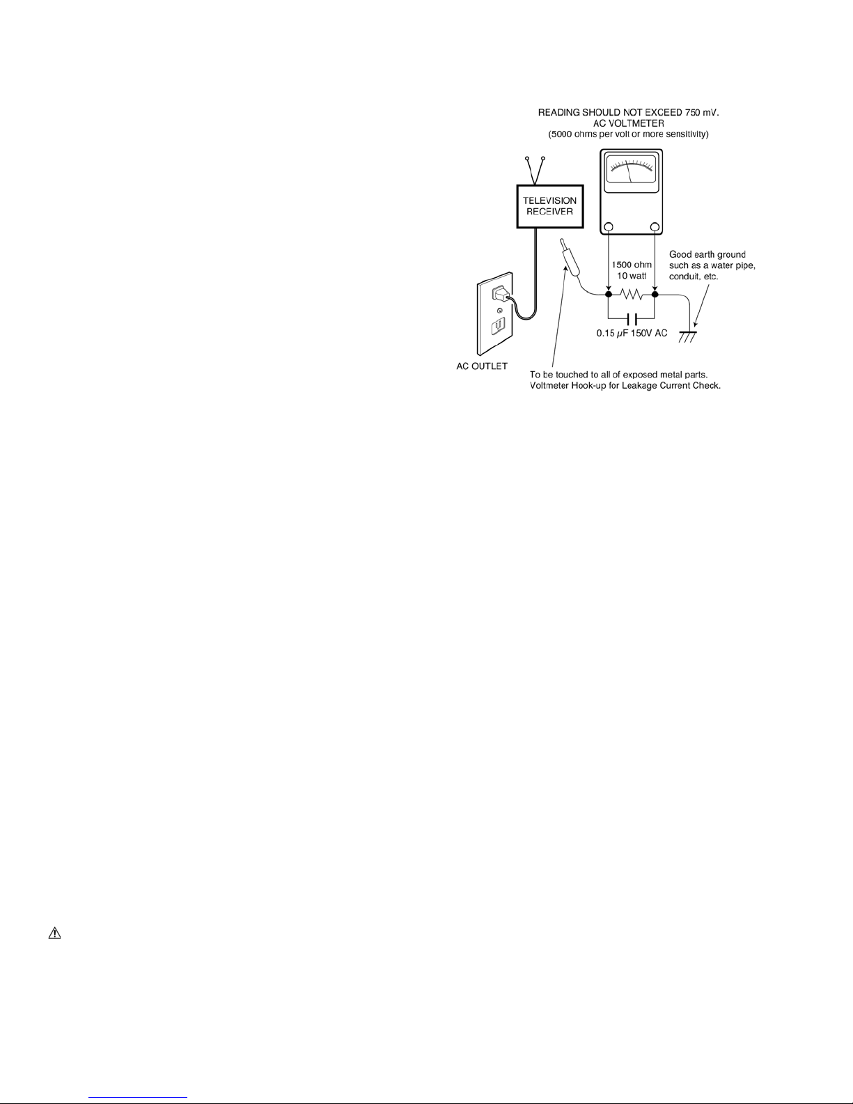
LEAKAGE CURRENT CHECK
Plug the AC line cord directly into a 120 VAC outlet. (Do not
use an isolation transformer for this check.) Use an AC volt-
meter, that has 5000 ohms per volt or more sensitivity.
Connect a 1500 ohm 10 watt resistor, paralleled by a 0.15 μF
150 VAC capacitor, between a known good earth ground
(water pipe, conduit, etc.) and all exposed metal parts of the
cabinet (antennas, handle bracket, metal cabinet, screw
heads, metal overlays, control shafts, etc.). Measure the AC
voltage across the 1500 ohm resistor. The AC voltage
should not exceed 750 mV. A reading exceeding 750 mV
indicates that a dangerous potential exists. The fault must
be located and corrected. Repeat the above test with the
receiver power plug reversed.
NEVER RETURN A RECEIVER TO THE CUSTOMER
WITHOUT TAKING THE NECESSARY CORRECTIVE ACTION.
PRODUCT SAFETY NOTICE
When replacing components in a receiver, always keep in
mind the necessary product safety precautions. Pay special
attention to the replacement of components marked with a
in the parts list and in the schematic diagrams. To ensure
safe product operation, it is necessary to replace those com-
ponents with the exact same PARTS.
SERVICING ELECTROSTATICALLY SENSITIVE DEVICES
Semiconductors (solid-state devices) that can be damaged
by static electricity are referred to as Electrostatically
Sensitive (ES) devices. Examples of typical ES devices are:
Integrated Circuits (IC), Field-Effect Transistors (FET), and
“chip” components. The following techniques should be
observed strictly, to reduce the occurrence of semiconduc-
tor damage due to electrostatic discharge.
1. Immediately prior to handling any semiconductor com-
ponent or an assembly containing a semiconductor
device or devices, discharge the electrostatic buildup on
your body by touching a known earth ground. You may
also obtain and wear a commercially available discharg-
ing wrist strap device.
CAUTION: Be sure to remove the wrist strap before
applying power to any unit being serviced.
2. After removing an ES equipped assembly, place it on a
conductive surface, such as, aluminum foil, to prevent
buildup or exposure to static electricity.
3. Use only grounded-tip soldering irons to solder or unsol-
der ES devices.
4. Use only anti-static solder removal devices. Some suc-
tion-type devices can generate static electricity adequate
to damage ES devices.
5. A replacement ES device will come packaged in protective
material (conductive foam, aluminum foil, or some compa-
rable conductive material). Do Not remove an ES device
from its protective packaging unless you are prepared to
install it immediately.
6. Precisely prior to removing an ES device from its protective
packaging, touch the protective packaging to the chassis or
assembly in which the device will be installed.
CAUTION: Be sure that no power is applied to the chassis
or circuit assembly.
7. Incidental body movements, such as, lifting a foot from
a carpeted floor or the rubbing of fabric together can
generate static electricity sufficient to damage ES devices.
Therefore, minimize all body movements while handling
exposed (unpackaged) ES devices.
SAFETY INSTRUCTIONS

– 3 –
SERVICE ADJUSTMENTS
GENERAL
This set has an On-screen Service Menu system included in
the CPU that allows remote operation for most of the
service adjustments.
ON-SCREEN SERVICE MENU SYSTEM
1. Enter the Service Menu:
•Turn off the receiver and disconnect the AC power
supply.
•While pressing the Volume (––) button on the televi-
sion, reconnect the AC power supply. The Service
Menu will now appear. The remote can now be used
to make adjustments. See Figure 1 below.
2. Service Adjustments:
•Press the Cursor and key to select the desired
service menu item you want to adjust. See page 4 for
the On-screen Service Menu.
•Use the Cursor or key to adjust the data.
The or key will increase or decrease the data
sequentially.
3. Exit from the Service Menu:
•Press the MENU key to turn off the Service Menu
display.
Figure 1. Service Menu Display
HEX DATA
Index ParameterName
FACTORY_VOL 0x21 48 0 255
Value Def. MIN MAX
1
ITEM NO. TITLE
SUB CH
INFO DYN VOL
Menu:
Exit Service Menu
Cursor :
Select Item
Cursor :
Adjust the data
Volume – :Enter Service Menu

– 4 –
ON-SCREEN SERVICE MENU
Table 1. ON-SCREEN SERVICE MENU
When IC801 (EEPROM) is replaced, check the bus data to confirm they are the same as below. See page 3 for
On-Screen Service Menu access and adjustments.
PROGRAM CODES
The microprocessor used in this model is a multi-purpose type and is used in several different models. To ensure
proper operation and the correct features for your particular model, the program codes must be correct.
Note 1. Option Data 1 (No. 2 OP1) should be hexadecimal 00.
See 2 above. If this program code is wrong the TV will not operate properly.
Note 2. Option Data 2 (No. 3 OP2) should be hexadecimal 1B.
See 3 above. If this program code is wrong the TV will not operate properly.
NOTES: Option 1 and Option 2 data is initial and can be set according to adjusment information.
Option 2 Data (Display Panel)
No. Title Initial Data Note
1A0 MUTE A0h Audio mute at Power ON
086 VOL 30h Volume setup inspection
087 OP1 00h Option 1 Data (HDMI)
088 OP2 1Bh Option 2 Data (Display Panel)
101 1R00 00h ROM Correction Data
102 1R01 00h ROM Correction Data
↓↓ ↓ ↓
197 2R47 00h ROM Correction Data
198 2R48 00h ROM Correction Data

– 5 –
POWER FAILURE CIRCUIT
Check the following if the unit is turned off by the power
failure detector.
1. Disconnect the AC power cord (120V AC line) for a short
time.
2. Connect a DC Voltmeter to the circuits shown below.
3. Press the Power key and check for the proper voltage
supplies.
4. If any of these voltages is low, the power failure detec-
tor should turn the unit off within three seconds.
5. Check all circuits shown below.
Note: If power failure is detected 3 times in 15 minutes,
the set will enter the standby mode and cannot be
switched On.To reset the operating programs of the
CPU it is necessary to disconnect the AC cord for a
short time.
CPU (IC800) is programmed so the set will go to standby
mode when there is circuit failure as described below.
(Refer to“Block Diagram Power Lines”.)
This unit is equipped with a Power Failure Detector function
included in the CPU which checks for an abnormal condi-
tion in the chassis power supplies.
If, while the power is on, a failure is caused by any of the
following that results in a low voltage supply, the CPU will
turn the unit off in 1.5 seconds to prevent further damage:
•Failure within the power supply circuits.
•A short circuit in the load side from the supply.
Power Failure: Detected voltage failure for circuit.
(Connected to IC800 pin 48 and pin 23.)
(Normal: High; Failure: Low)
If, while the power is off, the power is switched on and any
of these failures remains uncorrected, the CPU will shut off
the power within three seconds.
48
18
IC800 (SUB-CPU)
4,2
3
23
Power Fail 1
Power On
Power Fail 2
1
Power Board
Inverter
Main
D1671
K8B
D1660
D1681
Audio_Pow
13V
IC1660
9V
12V
5V
STAND BY
D1621
3
D1620 IC1630
3.3V

– 6 –
BACK CABINET REMOVAL
Remove 59 screws to take the back cabinet off.
(A:4x10, 31 pcs.; C:4x8, 28 pcs.)
MECHANICAL DISASSEMBLY
CAUTION:
This PDP TV uses several different kinds of screws. Using the correct screw is necessary to prevent damage.
Lead wires must be redressed to their previous locations after servicing. The Earth sheet and gasket are
provided to prevent interference to other radio and television receivers. The Earth sheet and gasket should
be returned to its previous position after servicing.
STAND REMOVAL
Position TV face down on a padded or cushioned surface to protect the screen and finish.
Remove 4 screws (B:6X16) and lift up TV from the stand.
B
A
A
AA
C
CC
C
A
C
positioning point positioning point

– 7 –
ELECTROSTATICALLY SENSITIVE DEVICES
Many solid-state devices (especially Integrated Circuits) are Electrostatically Sensitive,
and, therefore, require special handling techniques as described under “Servicing
Electrostatically Sensitive Devices,” on page two in this service literature.
Nut (Tuner)
Main Board
FF
EED
DD
F
FF
MECHANICAL DISASSEMBLY (Continued)
12
44
3
1: Main (Digital) Board 3: KEY SW Board
2: RC LED Board 4: Speakers
ANALOG AND MAIN BOARD REMOVAL
Remove 10 screws (D: 3X10, 3pcs; E:PC terminal
nuts, 2pcs; F:3X6, 5pcs) and 1 Nut (Tuner) to take the
Main Board off.
BOARD LOCATIONS

– 8 –
MECHANICAL DISASSEMBLY (Continued)
AMounting Frame
A
FILTER GLASS REMOVAL
1. Remove 4 screws (A:4x10) to take the panel module and panel holders (Mounting Frames) with boards off.
Filter Grass
A
3. Remove 5 screws (A:4x10) to take the shield front (4 pcs) and the filter glass off.

– 9 –
MECHANICAL DISASSEMBLY (Continued)
KEY SW BOARD REMOVAL
Remove 2 screws (D:3x10) to take the key sw board off.
RC LED BOARD REMOVAL
Remove 1 screw (D:3x10) to take the RC Led board off.
KEY SW Board
DD
DEC IND
AA
A
A
Speaker
Speaker
D
RC LED Board
DEC IND
SPEAKER REMOVAL
Remove 4 screws (A:4x10) to take off both speakers.

– 10 –
C
Mounting Frame
CC
C
PANEL MODULE REMOVAL
1. Remove the 4 screws (C:4x8) from the Mounting Frames to take the panel module off.
CAUTION:
This PDP TV uses several different kinds of screws. Using the correct screw is necessary to prevent damage.
Lead wires must be redressed to their previous locations after servicing. The Earth sheet and gasket are
provided to prevent interference to other radio and television receivers. The Earth sheet and gasket should
be returned to its previous position after servicing.

– 11 –
CHASSIS ELECTRICAL PARTS LIST
CAUTION: To Protect against electrical shock and for continued product safety, refer to SAFETY PRECAUTIONS
and PRODUCT SAFETY NOTICE on Page 2.
PRODUCT SAFETY NOTICE
PRODUCT SAFETY SHOULD BE CONSIDERED WHEN A REPLACEMENT IS MADE IN ANY AREA OF A RECEIVER.
COMPONENTS INDICATED BY A IN THIS PARTS LIST AND THE SCHEMATIC DIAGRAM DESIGNATE
COMPONENTS IN WHICH SAFETY CAN BE OF SPECIAL SIGNIFICANCE. IT IS PARTICULARLY RECOMMENDED
THAT ONLY PARTS DESIGNATED ON THE FOLLOWING PARTS LIST BE USED FOR COMPONENT REPLACE-
MENT DESIGNATED BY A . NO DEVIATIONS FROM RESISTANCE, WATTAGE, AND VOLTAGE RATINGS MAY
BE MADE FOR REPLACEMENT ITEMS DESIGNATED BY A .
Schematic
Location Part No. Description Schematic
Location Part No. Description
Note: Schematic part location numbers may not always match with the part descriptions.
The part descriptions are correct and should be used.
CAPACITORS RESISTORS

– 12 –
Schematic
Location Part No. Description Schematic
Location Part No. Description
“ASSY,PWB,MAIN_B-J4JF_SEI”
CAPACITORS
C001 F1H1H102A219 CERAMIC 1000P K 50V
C002 F1H1H102A219 CERAMIC 1000P K 50V
C003 F1J1E105A171 CERAMIC 1U K 25V
C004 F1J1E105A171 CERAMIC 1U K 25V
C005 F1H1H102A219 CERAMIC 1000P K 50V
C006 F1H1H102A219 CERAMIC 1000P K 50V
C007 F1H1H102A219 CERAMIC 1000P K 50V
C008 F1H1H102A219 CERAMIC 1000P K 50V
C009 F1H1H104A913 CERAMIC 0.1U K 50V
C010 F1H1H104A913 CERAMIC 0.1U K 50V
C011 F1H1H104A913 CERAMIC 0.1U K 50V
C012 F1H1H104A913 CERAMIC 0.1U K 50V
C013 F1H1H104A913 CERAMIC 0.1U K 50V
C014 F1H1H104A913 CERAMIC 0.1U K 50V
C015 F1H1H104A913 CERAMIC 0.1U K 50V
C016 F1H1H104A913 CERAMIC 0.1U K 50V
C017 F2A1E1020115 ELECT 1000U M 25V
C018 F1H1H331A792 CERAMIC 330P J 50V
C019 F1H1H331A792 CERAMIC 330P J 50V
C020 F1J1E105A171 CERAMIC 1U K 25V
C021 F1H1H104A913 CERAMIC 0.1U K 50V
C022 F1H1H104A913 CERAMIC 0.1U K 50V
C023 F1J1E105A171 CERAMIC 1U K 25V
C024 F1H1H104A913 CERAMIC 0.1U K 50V
C025 F1H1H104A913 CERAMIC 0.1U K 50V
C026 F1H1H104A913 CERAMIC 0.1U K 50V
C027 F1H1H104A913 CERAMIC 0.1U K 50V
C028 F1H1H1500009 CERAMIC 15P J 50V
C029 F1H1H1500009 CERAMIC 15P J 50V
C030 F1H1H104A220 CERAMIC 0.1U Z 50V
C031 F1H1H6810003 CERAMIC 680P J 50V
C032 F1H1H1010005 CERAMIC 100P J 50V
C033 F1H1H472A219 CERAMIC 4700P K 50V
C034 F1H1H104A913 CERAMIC 0.1U K 50V
C035 F1H1H104A913 CERAMIC 0.1U K 50V
C036 F1J1E105A171 CERAMIC 1U K 25V
C037 F1J1E105A171 CERAMIC 1U K 25V
C038 F1H1H103A219 CERAMIC 0.01U K 50V
C040 F1H1H104A913 CERAMIC 0.1U K 50V
C041 F1H1H104A913 CERAMIC 0.1U K 50V
C042 F1H1H104A913 CERAMIC 0.1U K 50V
C802 F1H1A105A036 CERAMIC 1U K 10V
C803 F1H1H104A913 CERAMIC 0.1U K 50V
C806 F2A0J2210063 ELECT 220U M 6.3V
C808 F1H1H104A220 CERAMIC 0.1U Z 50V
C809 F1H1A105A036 CERAMIC 1U K 10V
C813 F1H1H104A220 CERAMIC 0.1U Z 50V
C820 F1H1H104A220 CERAMIC 0.1U Z 50V
C821 F1H1H1800004 CERAMIC 18P J 50V
C822 F1H1H2200008 CERAMIC 22P J 50V
C1002 F1H1A105A036 CERAMIC 1U K 10V
C1004 F1H1A105A036 CERAMIC 1U K 10V
C1006 F1H1A105A036 CERAMIC 1U K 10V
C1009 F1H1A105A036 CERAMIC 1U K 10V
C1010 F1H1A105A036 CERAMIC 1U K 10V
C1012 F1H1A105A036 CERAMIC 1U K 10V
C1014 F1H1A105A036 CERAMIC 1U K 10V
C1016 F1H1A105A036 CERAMIC 1U K 10V
C1025 F1H1H471A792 CERAMIC 470P J 50V
C1201 F1H1H104A220 CERAMIC 0.1U Z 50V
C1600 F1H1H104A913 CERAMIC 0.1U K 50V
C1601 F1H1H104A913 CERAMIC 0.1U K 50V
C1602 F1H1H104A913 CERAMIC 0.1U K 50V
C1603 F1H1H104A913 CERAMIC 0.1U K 50V
C1610 F2A1V4710080 ELECT 470U M 35V
C1611 F1H1E224A098 CERAMIC 0.22U K 25V
C1612 F1H1H223A219 CERAMIC 0.022U K 50V
C1613 F1J1E105A171 CERAMIC 1U K 25V
C1615 F1H1H222A219 CERAMIC 2200P K 50V
C1616 F1J0J106A004 CERAMIC 10U K 6.3V
F1J0J106A020 CERAMIC 10U K 6.3V
C1617 F2A0J1020089 ELECT 1000U M 6.3V
C1630 F2A1V4710080 ELECT 470U M 35V
C1631 F1H1E224A098 CERAMIC 0.22U K 25V
C1632 F1H1H223A219 CERAMIC 0.022U K 50V
C1633 F1J1E105A171 CERAMIC 1U K 25V
C1635 F1H1H472A219 CERAMIC 4700P K 50V
C1636 F1J0J106A004 CERAMIC 10U K 6.3V
F1J0J106A020 CERAMIC 10U K 6.3V
C1637 F2A0J1020089 ELECT 1000U M 6.3V
C1640 F2A0J2210063 ELECT 220U M 6.3V
C1641 F1H1A105A036 CERAMIC 1U K 10V
C1643 F1H1A105A036 CERAMIC 1U K 10V
C1644 F1H1A105A036 CERAMIC 1U K 10V
C1645 F2A0J1020089 ELECT 1000U M 6.3V
C1651 F2A0J1020089 ELECT 1000U M 6.3V
C1660 F1H1H104A220 CERAMIC 0.1U Z 50V
C1661 F1J1E105A171 CERAMIC 1U K 25V
C1662 F2A1C101B828 ELECT 100U M 16V
C1663 F1H1H104A220 CERAMIC 0.1U Z 50V
C1664 F2A1C101B828 ELECT 100U M 16V
C1700 F2A1V4710080 ELECT 470U M 35V
C1701 F1H1E474A100 CERAMIC 0.47U K 25V
C1702 F1H1H223A219 CERAMIC 0.022U K 50V
C1703 F1K1H105A138 CERAMIC 1U K 50V
C1705 F1H1H472A219 CERAMIC 4700P K 50V
C1706 F1K1E4750002 CERAMIC 4.7U K 25V
C1707 F2A1E102B736 ELECT 1K U M 25V
C1801 F1H1H104A220 CERAMIC 0.1U Z 50V
C1815 F2A0J2210063 ELECT 220U M 6.3V
C1816 F1J0J106A004 CERAMIC 10U K 6.3V
F1J0J106A020 CERAMIC 10U K 6.3V
C2403 F1H1H104A220 CERAMIC 0.1U Z 50V
C2404 F1H1H104A220 CERAMIC 0.1U Z 50V
C2405 F1H1A105A036 CERAMIC 1U K 10V

– 13 –
Schematic
Location Part No. Description Schematic
Location Part No. Description
C2407 F1H1A105A036 CERAMIC 1U K 10V
C2409 F1H1H1010005 CERAMIC 100P J 50V
C2410 F1H1H1010005 CERAMIC 100P J 50V
C2416 F1H1H104A220 CERAMIC 0.1U Z 50V
C2417 F1H1H104A220 CERAMIC 0.1U Z 50V
C2418 F1H1H104A220 CERAMIC 0.1U Z 50V
C2440 F1H1H4700006 CERAMIC 47P J 50V
C2441 F1H1H4700006 CERAMIC 47P J 50V
C5500 F1J0J106A004 CERAMIC 10U K 6.3V
F1J0J106A020 CERAMIC 10U K 6.3V
C5501 F1J0J106A004 CERAMIC 10U K 6.3V
F1J0J106A020 CERAMIC 10U K 6.3V
C5502 F1J0J106A004 CERAMIC 10U K 6.3V
F1J0J106A020 CERAMIC 10U K 6.3V
C5503 F1J0J106A004 CERAMIC 10U K 6.3V
F1J0J106A020 CERAMIC 10U K 6.3V
C5504 F1H1A105A036 CERAMIC 1U K 10V
C5505 F1H1H104A220 CERAMIC 0.1U Z 50V
C5506 F1H1A105A036 CERAMIC 1U K 10V
C5507 F1H1H104A220 CERAMIC 0.1U Z 50V
C5508 F1H1A105A036 CERAMIC 1U K 10V
C5509 F1H1A105A036 CERAMIC 1U K 10V
C5510 F1H1H104A220 CERAMIC 0.1U Z 50V
C5511 F1H1A105A036 CERAMIC 1U K 10V
C5512 F1H1A105A036 CERAMIC 1U K 10V
C5514 F1H1A105A036 CERAMIC 1U K 10V
C5515 F1H1H104A220 CERAMIC 0.1U Z 50V
C5516 F1H1A105A036 CERAMIC 1U K 10V
C5517 F1H1H104A220 CERAMIC 0.1U Z 50V
C5518 F1H1H104A220 CERAMIC 0.1U Z 50V
C5519 F1H1A105A036 CERAMIC 1U K 10V
C5520 F1H1H104A220 CERAMIC 0.1U Z 50V
C5521 F1H1H104A220 CERAMIC 0.1U Z 50V
C5522 F1H1H104A220 CERAMIC 0.1U Z 50V
C5523 F1H1A105A036 CERAMIC 1U K 10V
C5524 F1H1H1010005 CERAMIC 100P J 50V
C5525 F1H1A105A036 CERAMIC 1U K 10V
C5526 F1H1A105A036 CERAMIC 1U K 10V
C5527 F1J0J106A004 CERAMIC 10U K 6.3V
F1J0J106A020 CERAMIC 10U K 6.3V
C5528 F1H1A105A036 CERAMIC 1U K 10V
C5529 F1H1A105A036 CERAMIC 1U K 10V
C5530 F1H1H104A220 CERAMIC 0.1U Z 50V
C5531 F1H1H104A220 CERAMIC 0.1U Z 50V
C5532 F1H1H104A220 CERAMIC 0.1U Z 50V
C5533 F1H1A105A036 CERAMIC 1U K 10V
C5534 F1H1H104A220 CERAMIC 0.1U Z 50V
C5535 F1J0J106A004 CERAMIC 10U K 6.3V
F1J0J106A020 CERAMIC 10U K 6.3V
C5536 F1J0J106A004 CERAMIC 10U K 6.3V
F1J0J106A020 CERAMIC 10U K 6.3V
C5537 F1H1A105A036 CERAMIC 1U K 10V
C5538 F1H1H103A219 CERAMIC 0.01U K 50V
C5539 F1H1A105A036 CERAMIC 1U K 10V
C5540 F1H1A105A036 CERAMIC 1U K 10V
C5541 F1H1A105A036 CERAMIC 1U K 10V
C5542 F1H1A105A036 CERAMIC 1U K 10V
C5544 F1H1H104A220 CERAMIC 0.1U Z 50V
C5545 F1J0J106A004 CERAMIC 10U K 6.3V
F1J0J106A020 CERAMIC 10U K 6.3V
C5547 F1H1H104A220 CERAMIC 0.1U Z 50V
C5548 F1J0J106A004 CERAMIC 10U K 6.3V
F1J0J106A020 CERAMIC 10U K 6.3V
C5549 F1H1A105A036 CERAMIC 1U K 10V
C5550 F1H1A105A036 CERAMIC 1U K 10V
C5551 F1H1H104A220 CERAMIC 0.1U Z 50V
C5552 F1H1A105A036 CERAMIC 1U K 10V
C5553 F1H1H103A219 CERAMIC 0.01U K 50V
C5554 F1H1A105A036 CERAMIC 1U K 10V
C5555 F1H1A105A036 CERAMIC 1U K 10V
C5556 F1J0J106A004 CERAMIC 10U K 6.3V
F1J0J106A020 CERAMIC 10U K 6.3V
C5557 F1H1A105A036 CERAMIC 1U K 10V
C5559 F1H1H7R00007 CERAMIC 7P D 50V
C5560 F1H1A105A036 CERAMIC 1U K 10V
C5561 F1H1H7R00007 CERAMIC 7P D 50V
C5562 F1J0J106A004 CERAMIC 10U K 6.3V
F1J0J106A020 CERAMIC 10U K 6.3V
C5564 F1H1H104A220 CERAMIC 0.1U Z 50V
C5565 F1H1A105A036 CERAMIC 1U K 10V
C5566 F1H1H104A220 CERAMIC 0.1U Z 50V
C5567 F1H1H103A219 CERAMIC 0.01U K 50V
C5568 F1H1A105A036 CERAMIC 1U K 10V
C5569 F1J0J106A004 CERAMIC 10U K 6.3V
F1J0J106A020 CERAMIC 10U K 6.3V
C5570 F1H1A105A036 CERAMIC 1U K 10V
C5571 F1H1H104A913 CERAMIC 0.1U K 50V
C5572 F1H1H104A913 CERAMIC 0.1U K 50V
C5573 F1H1H104A913 CERAMIC 0.1U K 50V
C5574 F1H1H104A913 CERAMIC 0.1U K 50V
C5575 F1H1H103A219 CERAMIC 0.01U K 50V
C5576 F1H1A105A036 CERAMIC 1U K 10V
C5577 F1H1H104A913 CERAMIC 0.1U K 50V
C5578 F1J0J106A004 CERAMIC 10U K 6.3V
F1J0J106A020 CERAMIC 10U K 6.3V
C5579 F1H1A105A036 CERAMIC 1U K 10V
C5580 F1H1H104A913 CERAMIC 0.1U K 50V
C5581 F1H1H104A913 CERAMIC 0.1U K 50V
C5582 F1H1A105A036 CERAMIC 1U K 10V
C5583 F1H1A105A036 CERAMIC 1U K 10V
C5584 F1H1H104A913 CERAMIC 0.1U K 50V
C5585 F1H1H103A219 CERAMIC 0.01U K 50V
C5586 F1H1A105A036 CERAMIC 1U K 10V
C5587 F1J0J106A004 CERAMIC 10U K 6.3V
F1J0J106A020 CERAMIC 10U K 6.3V
C5588 F1H1H104A913 CERAMIC 0.1U K 50V
C5589 F1J0J106A004 CERAMIC 10U K 6.3V

– 14 –
Schematic
Location Part No. Description Schematic
Location Part No. Description
F1J0J106A020 CERAMIC 10U K 6.3V
C5590 F1H1A105A036 CERAMIC 1U K 10V
C5591 F1H1H104A913 CERAMIC 0.1U K 50V
C5592 F1H1H104A913 CERAMIC 0.1U K 50V
C5593 F1H1H104A913 CERAMIC 0.1U K 50V
C5594 F1H1H104A220 CERAMIC 0.1U Z 50V
C5595 F1H1A105A036 CERAMIC 1U K 10V
C5596 F1H1A105A036 CERAMIC 1U K 10V
C5597 F1H1A105A036 CERAMIC 1U K 10V
C5598 F1H1H4R0A502 CERAMIC 4P C 50V
C5599 F1H1H4R0A502 CERAMIC 4P C 50V
C5602 F1H1A105A036 CERAMIC 1U K 10V
C5603 F1H1A105A036 CERAMIC 1U K 10V
C5604 F1H1A105A036 CERAMIC 1U K 10V
C5605 F1H1H104A220 CERAMIC 0.1U Z 50V
C5606 F1H1A105A036 CERAMIC 1U K 10V
C5607 F1H1H104A220 CERAMIC 0.1U Z 50V
C5608 F1H1H104A220 CERAMIC 0.1U Z 50V
C5609 F1H1H104A220 CERAMIC 0.1U Z 50V
C5610 F1H1H104A220 CERAMIC 0.1U Z 50V
C5611 F1H1A105A036 CERAMIC 1U K 10V
C5612 F1H1H103A219 CERAMIC 0.01U K 50V
C5613 F1H1A105A036 CERAMIC 1U K 10V
C5614 F1H1A105A036 CERAMIC 1U K 10V
C5615 F1H1H103A219 CERAMIC 0.01U K 50V
C5616 F1H1A105A036 CERAMIC 1U K 10V
C5617 F1J0J106A004 CERAMIC 10U K 6.3V
F1J0J106A020 CERAMIC 10U K 6.3V
C5618 F1H1A105A036 CERAMIC 1U K 10V
C5619 F1H1H104A220 CERAMIC 0.1U Z 50V
C5620 F1H1A105A036 CERAMIC 1U K 10V
C5621 F1H1A105A036 CERAMIC 1U K 10V
C5622 F2A0J2210063 ELECT 220U M 6.3V
C5623 F1H1H104A220 CERAMIC 0.1U Z 50V
C5624 F1H1H104A220 CERAMIC 0.1U Z 50V
C5625 F2A1H4R7B764 ELECT 4.7 U M 50V
C5630 F1H1A105A036 CERAMIC 1U K 10V
C5631 F2A1V4700087 ELECT 47U M 35V
C5650 F1H1H4700006 CERAMIC 47P J 50V
C5651 F1H1H4700006 CERAMIC 47P J 50V
C5652 F1H1H4700006 CERAMIC 47P J 50V
C5653 F1H1H4700006 CERAMIC 47P J 50V
C5654 F1H1H4700006 CERAMIC 47P J 50V
C5655 F1H1H4700006 CERAMIC 47P J 50V
C5656 F1H1H4700006 CERAMIC 47P J 50V
C5657 F1H1H4700006 CERAMIC 47P J 50V
C5658 F1H1H4700006 CERAMIC 47P J 50V
C5659 F1H1H4700006 CERAMIC 47P J 50V
C5660 F1H1H4700006 CERAMIC 47P J 50V
C5661 F1H1H4700006 CERAMIC 47P J 50V
C5662 F1H1H4700006 CERAMIC 47P J 50V
C5663 F1H1H4700006 CERAMIC 47P J 50V
C5664 F1H1H4700006 CERAMIC 47P J 50V
C5665 F1H1H4700006 CERAMIC 47P J 50V
C5666 F1H1H4700006 CERAMIC 47P J 50V
C5667 F1H1H4700006 CERAMIC 47P J 50V
C5702 F1H1H104A220 CERAMIC 0.1U Z 50V
C5703 F1J0J106A004 CERAMIC 10U K 6.3V
F1J0J106A020 CERAMIC 10U K 6.3V
C5704 F1H1A105A036 CERAMIC 1U K 10V
C5705 F1H1H104A220 CERAMIC 0.1U Z 50V
C5706 F1H1A105A036 CERAMIC 1U K 10V
C5707 F1H1H104A220 CERAMIC 0.1U Z 50V
C5709 F1J0J106A004 CERAMIC 10U K 6.3V
F1J0J106A020 CERAMIC 10U K 6.3V
C5710 F1H1A105A036 CERAMIC 1U K 10V
C5711 F1H1H104A220 CERAMIC 0.1U Z 50V
C5712 F1H1A105A036 CERAMIC 1U K 10V
C5713 F1H1A105A036 CERAMIC 1U K 10V
C5714 F1H1H104A220 CERAMIC 0.1U Z 50V
C5715 F1H1A105A036 CERAMIC 1U K 10V
C5716 F1H1H104A220 CERAMIC 0.1U Z 50V
C5717 F1H1H103A219 CERAMIC 0.01U K 50V
C5730 F2A0J2210062 ELECT 220U M 6.3V
C5731 F2A0J2210063 ELECT 220U M 6.3V
C5732 F1H1A105A036 CERAMIC 1U K 10V
C5737 F2A0J1020090 ELECT 1000U M 6.3V
C5750 F1H1A105A036 CERAMIC 1U K 10V
C5901 F1H1H104A220 CERAMIC 0.1U Z 50V
C5902 F1H1E224A098 CERAMIC 0.22U K 25V
C6101 F1H1H103A219 CERAMIC 0.01U K 50V
C6102 F1H1H103A219 CERAMIC 0.01U K 50V
C6105 F1H1H4700006 CERAMIC 47P J 50V
C6106 F1H1H4700006 CERAMIC 47P J 50V
C6110 F2A0J1020089 ELECT 1000U M 6.3V
C6111 F1H1H104A220 CERAMIC 0.1U Z 50V
C6112 F1H1H104A913 CERAMIC 0.1U K 50V
C6130 F1H1H102A219 CERAMIC 1000P K 50V
C6131 F1H1H102A219 CERAMIC 1000P K 50V
C6133 F1H1H1200004 CERAMIC 12P J 50V
C6134 F1H1H1200004 CERAMIC 12P J 50V
C6135 D0GBR00JA071 MT-GLAZE 0.000 ZA 1/10W
C6136 D0GBR00JA071 MT-GLAZE 0.000 ZA 1/10W
C6200 F1H1A105A036 CERAMIC 1U K 10V
C6201 F1H1A105A036 CERAMIC 1U K 10V
C6204 F1H1H471A792 CERAMIC 470P J 50V
C6205 F1H1H104A220 CERAMIC 0.1U Z 50V
C6206 F1H1H680A831 CERAMIC 68P J 50V
C6207 F1H1H680A831 CERAMIC 68P J 50V
C6208 F1H1H104A220 CERAMIC 0.1U Z 50V
C6209 F2A1H100B764 ELECT 10U M 50V
C6210 F1H1H680A831 CERAMIC 68P J 50V
C6211 F1H1H680A831 CERAMIC 68P J 50V
C6212 F1H1H471A792 CERAMIC 470P J 50V
C6213 F1H1A105A036 CERAMIC 1U K 10V
C6214 F1H1A105A036 CERAMIC 1U K 10V
C6510 F1H1H104A220 CERAMIC 0.1U Z 50V
C6533 F1H1H104A220 CERAMIC 0.1U Z 50V

– 15 –
Schematic
Location Part No. Description Schematic
Location Part No. Description
C6563 F1H1H104A220 CERAMIC 0.1U Z 50V
C6600 F1H1H104A220 CERAMIC 0.1U Z 50V
C6601 F1H1H104A220 CERAMIC 0.1U Z 50V
C6602 F1H1H104A220 CERAMIC 0.1U Z 50V
C6603 F1H1H104A220 CERAMIC 0.1U Z 50V
C6604 F1H1H104A220 CERAMIC 0.1U Z 50V
C6605 F1H1H104A220 CERAMIC 0.1U Z 50V
C6606 F1H1H104A220 CERAMIC 0.1U Z 50V
C6607 F1H1H104A220 CERAMIC 0.1U Z 50V
C6608 F1H1H104A220 CERAMIC 0.1U Z 50V
C6609 F1H1H104A220 CERAMIC 0.1U Z 50V
C6610 F1H1H104A220 CERAMIC 0.1U Z 50V
C6611 F1H1H104A913 CERAMIC 0.1U K 50V
C6612 F1H1H104A220 CERAMIC 0.1U Z 50V
C6613 F1H1H104A220 CERAMIC 0.1U Z 50V
C6614 F1H1H104A913 CERAMIC 0.1U K 50V
C6615 F1H1H104A220 CERAMIC 0.1U Z 50V
C6616 F1H1H104A220 CERAMIC 0.1U Z 50V
C6617 F1H1H104A220 CERAMIC 0.1U Z 50V
C6618 F1H1H104A913 CERAMIC 0.1U K 50V
C6630 F1H1H104A220 CERAMIC 0.1U Z 50V
C6631 F1J1E105A171 CERAMIC 1U K 25V
C6632 F2A0J2210063 ELECT 220U M 6.3V
C6633 F1H1H104A220 CERAMIC 0.1U Z 50V
C6634 F2A0J2210063 ELECT 220U M 6.3V
C6650 F1H1H104A220 CERAMIC 0.1U Z 50V
C6651 F1J1E105A171 CERAMIC 1U K 25V
C6652 F2A1V4700087 ELECT 47U M 35V
C6653 F1H1H104A220 CERAMIC 0.1U Z 50V
C6654 F2A1V4700087 ELECT 47U M 35V
C6655 F2A1V4700087 ELECT 47U M 35V
C8501 F1H1A105A036 CERAMIC 1U K 10V
C8503 F1H1H103A219 CERAMIC 0.01U K 50V
C8504 F2A0J2210063 ELECT 220U M 6.3V
DIODES
D002 B0ACCK000005 DIODE 1SS355-TE-17
B0ACCK000019 DIODE 1SS355
B0ACDJ000007 DIODE 1SS352-(TPH3)
D003 B0ACCK000005 DIODE 1SS355-TE-17
B0ACCK000019 DIODE 1SS355
B0ACDJ000007 DIODE 1SS352-(TPH3)
D007 B0BC6R100010 ZD UDZS-TE-176.2B
B0BC6R100025 ZENER DIODE 02DZ6.2Y(TPH3
B0BC6R2A0384 ZENER DIODE MM3Z6V2B
D008 B0BC6R100010 ZD UDZS-TE-176.2B
B0BC6R100025 ZENER DIODE 02DZ6.2Y(TPH3
B0BC6R2A0384 ZENER DIODE MM3Z6V2B
D801 B0BC3R9A0384 ZENER DIODE MM3Z3V9B
B0BC4R0A0006 ZD UDZS-TE-173.9B
DZ02DZ3.9Y—G ZENER DIODE 02DZ3.9Y(TPH3
D1000 B0BC3R9A0384 ZENER DIODE MM3Z3V9B
B0BC4R0A0006 ZD UDZS-TE-173.9B
DZ02DZ3.9Y—G ZENER DIODE 02DZ3.9Y(TPH3
D1001 B0BC3R9A0384 ZENER DIODE MM3Z3V9B
B0BC4R0A0006 ZD UDZS-TE-173.9B
DZ02DZ3.9Y—G ZENER DIODE 02DZ3.9Y(TPH3
D1610 B0JCPD000043 DIODE SS3P3-E3/84A
B0JCPD000046 DIODE SS3P3-M3/84A
D1620 B0ACCK000005 DIODE 1SS355-TE-17
B0ACCK000019 DIODE 1SS355
B0ACDJ000007 DIODE 1SS352-(TPH3)
D1621 B0BC3R0A0384 ZENER DIODE MM3Z3V0B
DZ02DZ3.0Y—G ZENER DIODE 02DZ3.0Y(TPH3
DZUDZS3.0B—G ZENER DIODE UDZS3.0B-TE-1
D1630 B0JCPD000043 DIODE SS3P3-E3/84A
B0JCPD000046 DIODE SS3P3-M3/84A
D1651 B0ACCK000005 DIODE 1SS355-TE-17
B0ACCK000019 DIODE 1SS355
B0ACDJ000007 DIODE 1SS352-(TPH3)
D1660 B0ACCK000005 DIODE 1SS355-TE-17
B0ACCK000019 DIODE 1SS355
B0ACDJ000007 DIODE 1SS352-(TPH3)
D1671 B0ACCK000005 DIODE 1SS355-TE-17
B0ACCK000019 DIODE 1SS355
B0ACDJ000007 DIODE 1SS352-(TPH3)
D1700 B0JCPD000043 DIODE SS3P3-E3/84A
B0JCPD000046 DIODE SS3P3-M3/84A
D2402 B0JCGD000002 DIODE RB551V-30-TE-17
D2403 B0JCGD000002 DIODE RB551V-30-TE-17
D6501 B0JCGD000002 DIODE RB551V-30-TE-17
D6502 B0JCGD000002 DIODE RB551V-30-TE-17
D6503 B0JCGD000002 DIODE RB551V-30-TE-17
D8500 B0ZBZ0000174 DIODE DF2S6.8UFS
D8501 B0ZBZ0000174 DIODE DF2S6.8UFS
INTEGRATED CIRCUITS
IC001 C1AB00003633 IC STA333BW13TR
IC800 QXXAAJQ1239— IC LC87F2932AVU-Y10LCD
IC800A C2BBYY000888 IC LC87F2932AVU-QIP-E
IC801 C3EBDC000091 IC CAT24C02WI-GT3
C3EBDY000038 IC LE24C023M-TLM-E
QXXAVC837—-P IC AT24C02BN-10SU-1.8
IC002 C0JBAA000505 IC 74AHCT1G08GW
C0JBCA000077 IC TC7SET08FU-(TE85L)
IC1200 C0JBAR000390 IC CD4052BNSR
C0JBAR000413 IC TC4052BF(EL)
IC1610 C0DBAYY00462 IC LV5803M-TE-L-E
IC1630 C0DBAYY00462 IC LV5803M-TE-L-E
IC1640 C0DBEYY00016 IC PQ070XNA1ZPH
IC1660 C0CBAYG00009 IC LM1117S-ADJ
IC1700 C0DBAYY00462 IC LV5803M-TE-L-E
IC1801 C0JBAA000505 IC 74AHCT1G08GW
C0JBCA000077 IC TC7SET08FU-(TE85L)
IC2401 C0JBAA000356 IC TC7SH08FU(TE85L)
IC2402 C0JBAA000356 IC TC7SH08FU(TE85L)

– 16 –
Schematic
Location Part No. Description Schematic
Location Part No. Description
IC2404 C0JBAA000356 IC TC7SH08FU(TE85L)
C0JBAA000484 IC 74AHC1G08GW
IC2405 C0JBAA000356 IC TC7SH08FU(TE85L)
C0JBAA000484 IC 74AHC1G08GW
IC5500 C1AB00003694 IC BCM35143KQLEG
IC5600 C3EBDC000091 IC CAT24C02WI-GT3
C3EBDY000038 IC LE24C023M-TLM-E
QXXAVC837—-P IC AT24C02BN-10SU-1.8
IC5623 C0JBAA000356 IC TC7SH08FU(TE85L)
C0JBAA000484 IC 74AHC1G08GW
IC5624 C0JBAA000356 IC TC7SH08FU(TE85L)
C0JBAA000484 IC 74AHC1G08GW
IC5700 C3ABSY000081 IC A3R12E4JFF-G8E
IC5730 C0DBEYY00016 IC PQ070XNA1ZPH
IC5750 QXXAAJQ1157— IC W25Q128BVFIG
IC5750A C3FBQY000054 IC W25Q128BVFIG
IC5900 C0EBY0000980 IC XC6108N28AMR
IC6200 C0ABBB000350 IC BA4558RF-E2
C0ABBB000450 IC NJM4558M-TE2
IC6600 QTDA9996——M IC TDA9996
IC6630 C0CBAYG00009 IC LM1117S-ADJ
IC6650 C0CBAYG00009 IC LM1117S-ADJ
IC8500 C0DBZYY00458 IC RT9711CGB
COILS
L001 G1C220MA0445 “INDUCTOR ,22UH”
L002 G1C220MA0445 “INDUCTOR ,22UH”
L003 G1C220MA0445 “INDUCTOR ,22UH”
L009 J0JCC0000371 “INDUCTOR , 120 OHM”
L011 J0JYC0000381 “INDUCTOR , 220 OHM”
L012 J0JYC0000381 “INDUCTOR , 220 OHM”
L013 G1C220MA0445 “INDUCTOR ,22UH”
L017 J0JCC0000371 “INDUCTOR , 120 OHM”
L800 G1C3R3MA0061 “INDUCTOR,3.3U M”
L801 G1C3R3MA0061 “INDUCTOR,3.3U M”
L1000 G1C3R3MA0061 “INDUCTOR,3.3U M”
L1200 G1C3R3MA0061 “INDUCTOR,3.3U M”
L1602 J0JYC0000381 “INDUCTOR , 220 OHM”
L1604 J0JYC0000381 “INDUCTOR , 220 OHM”
L1605 D0GDR00JA072 MT-GLAZE 0.000 ZA 1/10W
D0GDR00Z0002 MT-GLAZE 0.000 ZA 1/10W
L1606 J0JYC0000381 “INDUCTOR , 220 OHM”
L1607 D0GDR00JA072 MT-GLAZE 0.000 ZA 1/10W
D0GDR00Z0002 MT-GLAZE 0.000 ZA 1/10W
L1608 J0JYC0000381 “INDUCTOR , 220 OHM”
L1609 J0JYC0000381 “INDUCTOR , 220 OHM”
L1610 J0JYC0000381 “INDUCTOR , 220 OHM”
L1613 J0JYC0000381 “INDUCTOR , 220 OHM”
L1614 J0JYC0000381 “INDUCTOR , 220 OHM”
L1615 G1C100MA0445 INDUCTOR 10U M
L1616 D0GDR00JA072 MT-GLAZE 0.000 ZA 1/10W
D0GDR00Z0002 MT-GLAZE 0.000 ZA 1/10W
L1630 G1C100MA0445 INDUCTOR 10U M
L1631 D0GDR00JA072 MT-GLAZE 0.000 ZA 1/10W
D0GDR00Z0002 MT-GLAZE 0.000 ZA 1/10W
L1644 G1C100MA0445 INDUCTOR 10U M
L1661 D0GDR00JA072 MT-GLAZE 0.000 ZA 1/10W
D0GDR00Z0002 MT-GLAZE 0.000 ZA 1/10W
L1673 D0GDR00JA072 MT-GLAZE 0.000 ZA 1/10W
D0GDR00Z0002 MT-GLAZE 0.000 ZA 1/10W
L1674 D0GDR00JA072 MT-GLAZE 0.000 ZA 1/10W
D0GDR00Z0002 MT-GLAZE 0.000 ZA 1/10W
L1677 J0JYC0000381 “INDUCTOR , 220 OHM”
L1680 D0GDR00JA072 MT-GLAZE 0.000 ZA 1/10W
D0GDR00Z0002 MT-GLAZE 0.000 ZA 1/10W
L1716 G1C100MA0445 INDUCTOR 10U M
L2401 D0GBR00JA071 MT-GLAZE 0.000 ZA 1/10W
L5500 J0JYC0000381 “INDUCTOR , 220 OHM”
L5501 J0JCC0000371 “INDUCTOR , 120 OHM”
L5502 J0JCC0000371 “INDUCTOR , 120 OHM”
L5503 J0JCC0000371 “INDUCTOR , 120 OHM”
L5504 J0JCC0000371 “INDUCTOR , 120 OHM”
L5505 J0JCC0000371 “INDUCTOR , 120 OHM”
L5506 J0JCC0000371 “INDUCTOR , 120 OHM”
L5507 J0JCC0000371 “INDUCTOR , 120 OHM”
L5508 J0JCC0000371 “INDUCTOR , 120 OHM”
L5509 J0JCC0000371 “INDUCTOR , 120 OHM”
L5511 J0JCC0000371 “INDUCTOR , 120 OHM”
L5512 J0JCC0000371 “INDUCTOR , 120 OHM”
L5513 J0JCC0000371 “INDUCTOR , 120 OHM”
L5514 J0JCC0000371 “INDUCTOR , 120 OHM”
L5515 J0JCC0000371 “INDUCTOR , 120 OHM”
L5516 J0JCC0000371 “INDUCTOR , 120 OHM”
L5517 J0JCC0000371 “INDUCTOR , 120 OHM”
L5518 J0JCC0000371 “INDUCTOR , 120 OHM”
L5519 J0JCC0000371 “INDUCTOR , 120 OHM”
L5520 J0JCC0000371 “INDUCTOR , 120 OHM”
L5521 J0JCC0000371 “INDUCTOR , 120 OHM”
L5555 D0GB4R7J0002 MT-GLAZE 4.7 JA 1/10W
L5650 G1CR47JA0041 “INDUCTOR,0.47U J”
L5651 G1CR47JA0041 “INDUCTOR,0.47U J”
L5652 G1CR47JA0041 “INDUCTOR,0.47U J”
L5653 G1CR47JA0041 “INDUCTOR,0.47U J”
L5654 G1CR47JA0041 “INDUCTOR,0.47U J”
L5655 G1CR47JA0041 “INDUCTOR,0.47U J”
L5660 G1CR47JA0041 “INDUCTOR,0.47U J”
L5661 G1CR47JA0041 “INDUCTOR,0.47U J”
L5662 G1CR47JA0041 “INDUCTOR,0.47U J”
L5701 J0JYC0000381 “INDUCTOR , 220 OHM”
L5730 D0GDR00JA072 MT-GLAZE 0.000 ZA 1/10W
D0GDR00Z0002 MT-GLAZE 0.000 ZA 1/10W
L6100 D0GB121J0002 MT-GLAZE 120 JA 1/10W
L6101 D0GB121J0002 MT-GLAZE 120 JA 1/10W
L6104 D0GDR00JA072 MT-GLAZE 0.000 ZA 1/10W
D0GDR00Z0002 MT-GLAZE 0.000 ZA 1/10W
L6105 G1C3R3MA0061 “INDUCTOR,3.3U M”
L6117 J0JYC0000381 “INDUCTOR , 220 OHM”
Other manuals for DP50741
3
Table of contents
Other Sanyo TV manuals

Sanyo
Sanyo CP34ST3T User manual

Sanyo
Sanyo DP50741 User manual

Sanyo
Sanyo CT29FS1 User manual

Sanyo
Sanyo LCD-42XF4 User manual

Sanyo
Sanyo C14ZA20 User manual

Sanyo
Sanyo CA21XS2S User manual

Sanyo
Sanyo DS25520 User manual

Sanyo
Sanyo CE28FWN6-B User manual

Sanyo
Sanyo CM29FS2 User manual

Sanyo
Sanyo PDP-50XR7 User manual

Sanyo
Sanyo CP29KX2Z User manual

Sanyo
Sanyo CP21VF1 User manual

Sanyo
Sanyo CE19LD95-B User manual

Sanyo
Sanyo CE30LC3-C User manual

Sanyo
Sanyo C29ZK80 User manual

Sanyo
Sanyo CE15LC3-B User manual

Sanyo
Sanyo 28dn2 User manual

Sanyo
Sanyo ACI-A Installation guide

Sanyo
Sanyo CE 25MT2A-C User manual

Sanyo
Sanyo LCD-32XR11F User manual