Sapphire Pure Element PE-AM2RS485M User manual

1
SAPPHIRE PURE ELEMENT
Electronic Emission Notices
Federal Communications Commission (FCC) Statement
This equipment has been tested and found to comply with the limits for a Class B digital
device, pursuant to Part 15 of FCC Rules. These limits are designed to provide reasonable
protection against harmful interference in a residential installation. This equipment
generates, uses and can radiate radio frequency energy and, if not installed and used in
accordance with instructions contained in this manual, may cause harmful interference
to radio and television communications. However, there is no guarantee that interference
will not occur in a particular installation.
If this equipment does cause harmful interference to radio or television reception, which
can be determined by turning the equipment off and on, the user is encouraged to try to
correct the interference by one or more of the following measures:
- REORIENT OR RELOCATE THE RECEIVINGANTENNA
- INCREASE THE SEPARATION BETWEEN THE EQUIPMENTAND THE RECEIVER
- CONNECT THE EQUIPMENT INTO AN OUTLET ON A CIRCUIT DIFFERENT FROM
THAT OF THE RECEIVER
- CONSULTTHE DEALER OR AN EXPERIENCEDAUDIO/TELEVISION TECHNICIAN
NOTE: Connecting this device to peripheral devices that do not comply with Class B
requirements, or using an unshielded peripheral data cable, could also result in
harmful interference to radio or television reception.
The user is cautioned that any changes or modifications not expressly approved
by the party responsible for compliance could void the user’s authority to
operate this equipment.
To ensure that the use of this product does not contribute to interference, it is
necessary to use shielded I/O cables.
Copyright
This manual is copyrighted with all rights reserved. No portion of this manual may be
copied or reproduced by any means.
While every precaution has been taken in the preparation of this manual, no responsibility
for errors or omissions is assumed. Neither is any liability assumed for damages resulting
from the use of the information contained herein.
Trademarks
All brand names, logos and registered trademarks mentioned are property of their
respective owners.

2
PE-AM2RS485MPE-AM2RS485M
PE-AM2RS485M User’s Manual
TABLE OF CONTENTS
HARDWARE CONFIGURATION .................................................................... 4
Key Features .................................................................................................. 4
MOTHERBOARD LAYOUT ............................................................................ 7
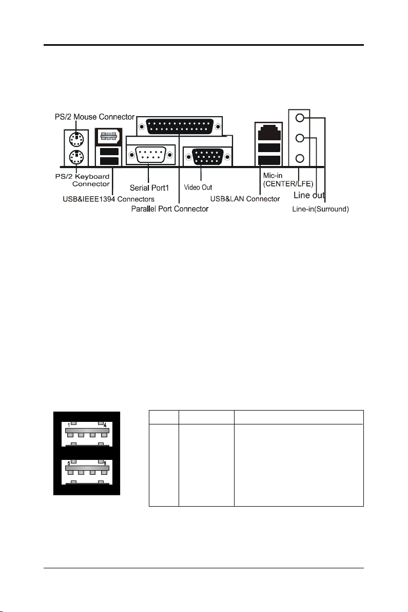
REAR PANEL ................................................................................................ 8
AUDIO CONFIGURATION .............................................................................. 10
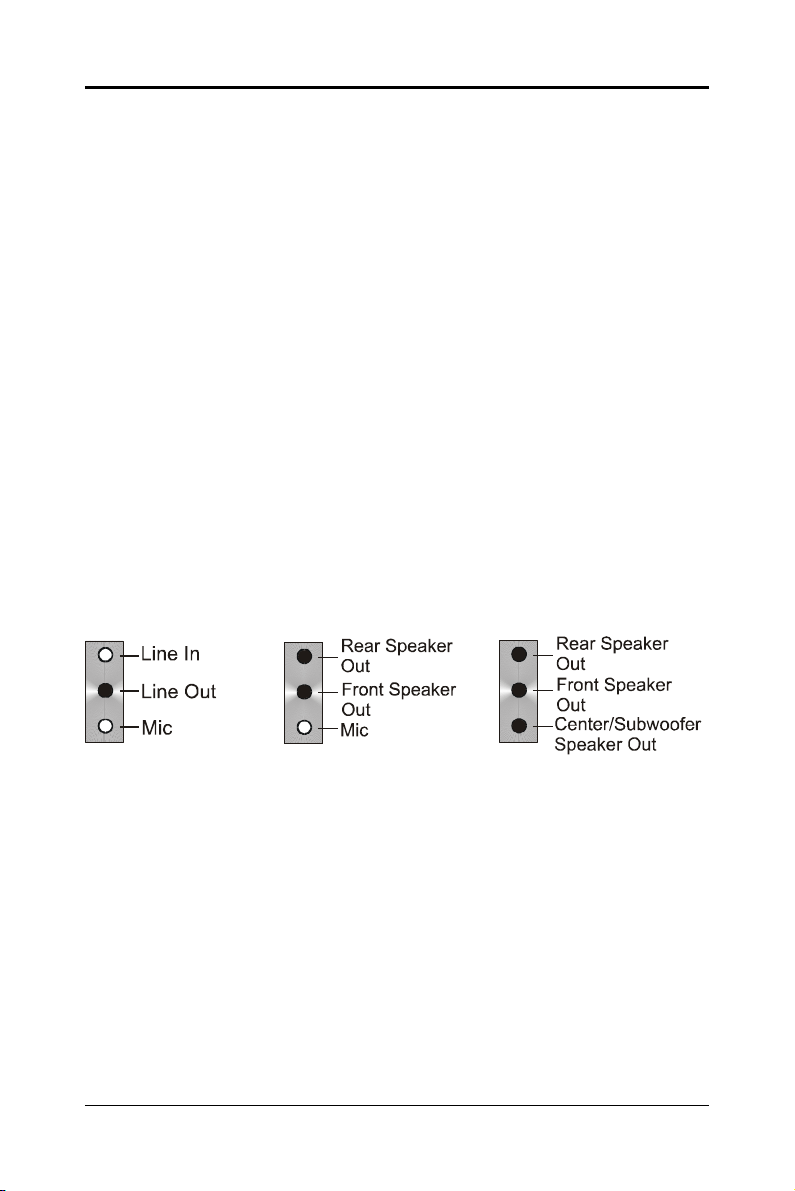
SPEAKER CONFIGURATION ........................................................................ 10
Method 1: Using the 4/6 surround audio output of the back panel only ..... 10
Method 2: Using S-Bracket connectors ...................................................... 12
CONNECTORS ............................................................................................. 14
Floppy Disk Drive Connector: CN3 ........................................................ 14
Hard Disk Connectors: CN1 .................................................................. 14
Back Panel Bracket-Six Channel Audio Output Connector: J19 .......... 15
TV Out Connector: J5 ............................................................................. 16
IEEE1394 Connector: J23 ..................................................................... 17
Chassis Alarm Lead: JP12 .................................................................... 18
Fan Power Connectors: CPUFAN1, SYSFAN1................................. ........ 19
Power LED: D25, D26................................. .............................................. 19
CD-IN Connector: J18 ........................................................................... 20
AUX-IN Connector: J20 .......................................................................... 20
Front Panel Audio Header: FP_S1 ......................................................... 21
USB Connectors: FP_U1, FP_U2,FP_U3 ............................................. 22
Front Panel Headers: FP1 ..................................................................... 23
Serial ATA Hard Disk Connectors: SATA1, SATA2, SATA3, SATA4 .......... 24
JUMPER SETTING ....................................................................................... 26
JP9-CMOS Clear .................................................................................... 26
JP2-On Board AC97 Sound Select ........................................................ 26
JP13-On Board LAN Select ................................................................... 26
JP3-On Board IEEE1394 Select ............................................................ 26

3
SAPPHIRE PURE ELEMENT
SLOTS ......................................................................................................... 27
CPU INSTALLATION .................................................................................... 28
MEMORY CONFIGURATIONS ...................................................................... 30
DDRII DIMM Sockets Location ............................................................... 30
Installing DDRII DIMMs .......................................................................... 31
Memory Configurations ......................................................................... 31
BIOS SETUP ..................................................................................... 32
About the Setup Utility ............................................................................ 32
Standard CMOS Features ..................................................................... 34
Advanced BIOS Features ....................................................................... 36
Advanced Chipset Features .................................................................. 39
Integrated Peripherals ........................................................................... 41
Power Management Setup .................................................................... 44
PnP/PCI Configurations ........................................................................ 46
PC Health Status ................................................................................... 47
Set Supervisor/User Password ............................................................. 49
BIOS Update Procedure ........................................................................ 50
SATA RAID SETUP (only for SB600) .............................................. 51
Press Ctrl+F to enter RAID utility ........................................................... 51
Define LD ............................................................................................... 52
Delete LD ............................................................................................... 52
SATA RAID SETUP (only for SB460) ................................................ 53
Creating RAID Sets ................................................................................ 53
Deleting RAID Sets ................................................................................ 54
DRIVER AND RAID SOFTWARE INSTALLATION ............................ 55
APPENDIX ....................................................................................... 56

4
PE-AM2RS485MPE-AM2RS485M
PE-AM2RS485M User’s Manual
HARDWARE CONFIGURATION
Key Features :
Chipset
• ATI® RS485+SB460/SB600 Chipset.
Processor
• Support for AMDTM K8 Processor in a Socket AM2 package.
• Support Hypertransport interface bus.
VRM (Voltage Regulator Modules) on Board
• Flexible motherboard design with on board VRM, easy to upgrade
with future AMDTM K8 processors.
• 0.800V to 1.55V in 25mV steps.
System Memory
•A total of four 240 pin DDRII SDRAM sockets.
• DIMM sizes from 64 Mbytes to 4Gbyte.
•Supports Dual Channel 128-bit Wide Memory Interface.
• Supports 533/667/800 DDRII SDRAM memory types.
System BIOS
•PnP, APM, ATAPI and Windows® 2000/XP.
• Full support of ACPI & DMI.
•Auto detects and supports LBA harddisk with capacities over 160GB.
•Easy to upgrade BIOS by end-user.
Plug and Play
•Supports Plug and Play specification 1.1.
•Plug and play for Windows® 2000, as well as Windows® XP.
•Fully steerable PCI interrupts.
On-board VGA
• Integrated ATI PCIE X300 graphic core.
• Supports CRT or TV Out display.
• Integrated DAC and CRT controllers.
• Full screen/full speed video playback.
• Up to 2048x1536, non-interlaced screen resolution for CRT.
TV Out
• Integrated TV encoder.
• 10-bit DAC with 4-tap filter.
• PAL/NTSC TV Out with Composite and S-Video outputs (via a header).
• ATI’s exclusive “Composite Dot Crawl” freeze option for PAL
and NTSC to improve the picture quality.
• TV-Out power management support.

5
SAPPHIRE PURE ELEMENT
Expanded USB Support
• Includes 2 OHCI host controllers.
• Includes 1 EHCI USB2.0 Host Controller that supports all ports
(Bandwidth is shared between the all ports).
• This motherboard supports USB 2.0 only on Windows® 2000
(with SP4 or above) and Windows® XP (with SP1 or above) operation
systems.
• SB600 support ten ports and SB460 support eight ports only.
PCI Express Graphics interface
• One 16-lane (X16 port) PCI Express graphics port, fully compliant
with the PCI Express Base Specification revision 1.0a.
• A base PCI Express frequency of 2.5Gb/s only.
• PCI Express support and Enhanced Addressing Mechanism.
PCI ExpressX1 Ports
• Full PCI Express 1.0a compliant.
• One virtual channel support for full isochronous data transfers.
• Support for full 2.5Gb/s bandwidth in each direction per X1 lane.
On-board I/O
• One on board PCI fast IDE ports supporting up to 2 ATA, ATA2 , Ultra
ATA33/66/100/133 IDE HDDs, CD-ROMs, ZIP drives and LS-120
drives as boot drive.
• One ECP/EPP parallel port.
• One 16550 Compatible UART serial port (via a header).
• One floppy port which supports two FDD of 1.44MB, 2.88MB capacity.
• Eight USB ports (four ports via two headers) for SB460.
• Ten USB ports (six ports via three headers) for SB600.
• PS/2 keyboard support.
• PS/2 mouse support.
• One front panel sound connector.
• Infrared (IrDA) support via a header.
On-board Realtek RTL8100C/RTL8110S PCI LAN (optional)
•Provides 32-bit performance, PCI bus master capability.
•Full compliance with IEEE 802.3u 100 Base-T specifications and
IEEE 802.3X Full Duplex Flow Control.
•Supports 10 Mb/s, 100 Mb/s and 1000 Mb/s (only for RTL8110S)
operation.
•Supports Wake-On-LAN function and remote wake-up.
•Supports ACPI, PCI Power management and PCI VPD.

6
PE-AM2RS485MPE-AM2RS485M
PE-AM2RS485M User’s Manual
Power Management
• Supports SMM, APM and ACPI.
• Break switch for instant suspend/resume on system operations.
• Energy star “Green PC” compliant.
• Hardware monitoring circuit provides voltage, fan speed, etc. monitoring
(optional).
• External Modem Ring-in Wake-up support.
• Supports suspend-to-RAM (STR) (optional).
(Note: Make sure that the current of your 5VSB power supply is more than
1.5A. Please use a 300 watt power supply or greater.)
On-board AC97 Sound (optional)
•Integrated AC97 controller with standard AC97 Codec.
• Direct Sound and Sound Blaster compatible.
•Full-Duplex 16-bit record and play back.
•PnP and APM 1.2 support.
•Windows® 2000/XP ready.
•Line-in, Line-out, Mic-in.
• Supports ALC655 AC97 codes for six sound channel output (optional).
On-board IEEE1394 (optional)
•Compliant with 1394 OHCI specifications v1.0 and v1.1.
• Integrated 400Mbit 2 port PHY.
On board Serial ATA host Controller (only for SB460)
•Independent DMA operation on four ports.
• Data transfer rates of 150Mb/s.
• RAID feature support .
On board Serial ATAII Host Controller (only for SB600)
• Independent DMA operation on four ports.
• Data transfer rates of 300Mb/s.
• RAID feature support .
Expansion Slots
• 1 PCI Express X16 slot.
• 1 PCI Express X1 slot.
•2 PCI slots, - ver. 2.2 compliant.
Static electricity can harm delicate components of the motherboard.
To prevent damage caused by static electricity, discharge the static
electricity from your body before you touch any of the computers
electronic components.

7
SAPPHIRE PURE ELEMENT
NOTE
1) Be sure to check the cable orientation in order to match the coloured strip
to the pin 1 end of the connector.
2) When you start up the system, please wait for 5 seconds after you power
on AC.
3) Adding a metal spaced plate to the back of the Socket 940 is not
recommended as this will short motherboard components and damage
the system.
MOTHERBOARD LAYOUT
The following diagram shows the relative positions of the jumpers, connectors,
major components and memory banks on the motherboard.

8
PE-AM2RS485MPE-AM2RS485M
PE-AM2RS485M User’s Manual
PIN SIGNAL DESCRIPTION
1 VCC +5V/5VSB (optional)
2 -Data 0 Negative Data Channel 0
3 +Data0 Positive Data Channel 0
4 GND Ground
5 VCC +5V/5VSB (optional)
6 -Data 1 Negative Data Channel 1
7 +Data 1 Positive Data Channel 1
8 GND Ground
REAR PANEL
The back panel provides the following connectors:
PS/2 Mouse Connector
The motherboard provides a standard PS/2® mouse mini DIN connector for
attaching a PS/2® mouse. You can plug a PS/2® mouse directly into this
connector.
PS/2 Keyboard Connector
The motherboard provides a standard PS/2® keyboard mini DIN connector for
attaching a PS/2® keyboard. You can plug a PS/2® keyboard directly into this
connector.
USB 2.0 Connector
The motherboard provides an OHCI (Open Host Controller Interface) Universal
Serial Bus root for attaching USB devices such as keyboard, mouse or other
USB-compatible devices. You can plug the USB device directly into the
connector.
USB 2.0 Connector DescriptionUSB 2.0 Connector

9
SAPPHIRE PURE ELEMENT
VIA VT6307 IEEE 1394 Connector (Optional)
The motherboard provides an IEEE 1394 Connector and allows you to connect
an IEEE 1394 device directly to the connector.
Video Out Connector (Optional)
The motherboard provides a Video out port to connect a 15-pin analog video
monitor.
SPDIF Connector (Optional)
The motherboard provides a S-Bracket (SPDIF) connector that allows you to
connect a S-Bracket (coaxial) for a Digital Interface (SPDIF).
LAN Jack (Optional)
The motherboard provides one standard RJ-45 jack for connecting to a Local
Area Network(LAN). You can connect a network cable to the LAN jack.
Parallel Port Connector: LPT1
The motherboard provides a 25-pin female centronic connector. A parallel port
is a standard printer port that supports Enhanced Parallel Port (EPP) and
Extended Capabilities Parallel Port (ECP) mode.
Audio Port Connector
Line_Out is a connector for speakers or headphones. Line_In is used for
external CD players, tape players, or other audio devices. Mic_In is the
microphone connector.
The ALC655 embeds an internal analog switch (by driver software) to select
LINE input or Surround output, and to select MIC input or CENTER/LFE output.

10
PE-AM2RS485MPE-AM2RS485M
PE-AM2RS485M User’s Manual
AUDIO CONFIGURATION
After installing the audio driver, you can select 2/4/6 channel surround audio
output in the software utility and then connect surround speakers to appropriate
audio ports.
There are two ways to obtain 4/6 channel surround audio output:
1. Using the 4/6 surround audio output of the back panel only. All surround
speakers connect to this audio connector.
2. Using the S-Bracket (optional cable). You have install the S-Bracket into the
computer. Connect two front speakers to back panel’s “Line Out” port, and
the rest of speakers to S-Bracket. For connection details, please refer to
page 15.
SPEAKER CONFIGURATION
Method 1:
Using the 4/6 surround audio output of the back panel only
After installing the audio drivers, you can attach the speakers for 2-/4-/6- channel
audio output. Please connect the speakers to the LINE OUT connectors.
Different connector configurations for 2-/4-/6-channel options are listed below:
2-Channel
In 2-channel
configuration, Line
Out, Line In and MIC
functions all exist.
4-Channel
When set to 4-channel
configuration, Line In
is replaced by Rear
Speaker Out. The Line
in function does not
exist.
6-Channel
When set to 6-channel
configuration, Line In is
replaced by Rear
Speaker Out. Mic is
replaced by Center/
Subwoofer Speaker Out.
Line in and Mic functions
do not exist.

11
SAPPHIRE PURE ELEMENT
In the software utility, double click the “AC97 Audio configuration” icon from
the window tray on the right bottom.
The “AC97 Audio Configuration” box will appear. Click on the Speaker
Configuration tab to select the audio mode.
A. When you choose 4-channel mode for 4 speaker output, the selected item
is shown (Figure 1).
B. When you choose 6-channel mode for 5.1 speaker output, the selected
item is shown (Figure 2).
(Figure 1)
(Figure 2)

12
PE-AM2RS485MPE-AM2RS485M
PE-AM2RS485M User’s Manual
Back Panel S-Bracket
(Front channels)
Description:
Connect two speakers to the back panel’s Line Out connector and two
speakers to one Line Out connector on the S-Bracket, or connect all four
speakers to one connector on the S-Bracket. If you want to use the Line In
function, please click the Rear Speaker Out button (shown below)
+
Method 2: Using S-BRACKET connectors:
The S-Bracket (shown on page 15) is an optional accessory. To use the
S-Bracket, you should select the correct setting in the software utility. For
information about the setting, refer to selecting 4- or 6- Channel Settings later
in this section.
Connector configurations for 4- and 6- channel using S-Bracket are described
below:
4-Channel Analog Audio Output
123
1 SPDIF jack (coaxial)
2 Rear Speaker Out
3 No function

13
SAPPHIRE PURE ELEMENT
6-Channel Analog Audio Output
Description:
Connect two speakers to the back panel’s Line Out connector and four
speakers to the Line Out connector of the S-Bracket, or attach all six speakers
to the connector on the S-Bracket. If you want to use the Line In and MIC
functions at the same time, please click the Rear Speaker Out and Center/
Subwoofer Speaker Out buttons (shown below).
Back Panel S-Bracket
(Front channels) +
123
1 SPDIF jack (coaxial)
2 Rear Speaker Out
3 Center and Subwoofer Out

14
PE-AM2RS485MPE-AM2RS485M
PE-AM2RS485M User’s Manual
CN3
CN1
1
1
Connectors
The motherboard provides connectors to connect to the FDD, IDE HDD, and
USB Ports and the CPU/System FAN etc.
Floppy Disk Drive Connector: CN3
The motherboard provides a standard floppy disk drive connector that supports
1.44M, 2.88M floppy disk types.
Hard Disk Connectors: CN1
The motherboard has a 32-bit Enhanced PCI IDE and Ultra DMA 33/66/100/
133 controller that provides PIO mode 0~4, Bus Master, and Ultra DMA 33/66/
100/133 function. You can connect up to two hard disk drives, CD-ROMs, 120MB
Floppy (reserved for future BIOS) and other devices.
CN1 (Primary IDE Connector)
The first hard drive should always be connected to CN1. CN1 can connect a
Master and a Slave drive. You must configure the second hard drive to Slave
mode by setting the jumper accordingly.

15
SAPPHIRE PURE ELEMENT
10
9
2
1
J19
S-Bracket (SPDIF) /CEN/LFE/Surround Output Connector - J19 (optional)
This connector allows you to connect a S-Bracket for a digital interface (SPDIF).
The S-Bracket offers 1 SPDIF jack for digital audio transmission and 2 analog
Line-Out jacks for other 4-channel audio outputs. So you can use Line in, Mic
in and 6 channel audio output features at the same time.
PIN SIGNAL DESCRIPTION
1 SOUT-L Audio left surrounding output
2 SOUT-R Audio right surrounding output
3 GND Ground
4 GND Ground
5 CET-OUT Audio center output
6 LFE-OUT Audio bass output
7 GND Ground
8 SPDIF S/PDIF input
9 KEY NC
10 SPDFO S/PDIF output
S-Bracket Cable (optional)
Connect to J19
Rear Speaker Out
Center and Subwoofer Out SPDIF jack (coaxial)

16
PE-AM2RS485MPE-AM2RS485M
PE-AM2RS485M User’s Manual
TV Out Connector
The motherboard provides TV Out connectors.
J5
J5 - Pin Definition
TV Out cable
1
2
PIN Assignment
1 KEY
2C
3 HDTV-DET
4Y
5NC
6 COM P/B
7NC
8 GND
9NC
10 GND

17
SAPPHIRE PURE ELEMENT
IEEE 1394 Connector: J23 (optional)
The mainboard provides two 1394 pin headers that allow you to connect
IEEE 1394 ports.
J23
1
2
9
10
IEEE 1394 Cable (optional)
J23 - Pin Definition
PIN Assignment
1TPA+
2TPA-
3 Ground
4 Ground
5 TPB+
6 TPB-
7 Cable power
8 Cable power
9 Key (no pin)
10 Ground

18
PE-AM2RS485MPE-AM2RS485M
PE-AM2RS485M User’s Manual
Chassis Alarm Lead: JP12 (optional)
This lead is for a chassis designed with an intrusion detection feature. This
requires an external detection mechanism such as a chassis intrusion sensor
or microswitch. When you remove any chassis component, the sensor triggers
and sends a high-level signal to this lead to record a chassis intrusion event.
JP12
1
PIN Assignment
1 +5VSB
2 KEY
3 Chassis Signal
4 GND
JP12 - Pin Definition
Note:
If you want to use “Chassis Alarm” Connector, you must remove 3-4 jumper.

19
SAPPHIRE PURE ELEMENT
Fan Power Connectors: CPUFAN1, SYSFAN1
The CPUFAN1 (processor fan) and SYSFAN1 (system fan) support system
cooling fans using +12V via four-pin head connectors. When connecting the
wire to the connectors, always take note that the red wire is the positive and
should be connected to the +12V, the black wire is Ground and should be
connected to GND. If the motherboard has a System Hardware Monitor chipset
on-board, you must use a specially designed fan with speed sensor to take
advantage of the CPU fan control.
Power LED: D25, D26 (optional)
The green LED lights when the system is in the power-on state.
The red LED lights whenever AC mains power is attached, irrespective of
whether the system is power-on or power-off or standby mode.
SYSFAN1
CPUFAN1
1
1
D25- +5V_LED (Green)
D26- 5VSB_LED (Red)

20
PE-AM2RS485MPE-AM2RS485M
PE-AM2RS485M User’s Manual
CD-IN Connector: J18
The connector is for CD-ROM Drive.
J18
PIN Assignment
1 CD-L
2 GND
3 GND
4 CD-R
CDS1 : J18 - Pin Definition
1
This manual suits for next models
1
Table of contents
Other Sapphire Pure Motherboard manuals
Popular Motherboard manuals by other brands

Telit Wireless Solutions
Telit Wireless Solutions GS2200M SKB quick start guide

Shuttle
Shuttle Spacewalker MS51 user manual

Portwell
Portwell (R)PEB-4702VLA Quick installation guide

Asus
Asus Z87-Deluxe/Dual user manual

mikroElektronika
mikroElektronika DALI Click quick start guide

Biostar
Biostar TA870U3+ Setup manual