SARIgas
ETF / ETFL / ETFW Page
10
Rev.0
INSTALLATION REGULATIONS
installation must by carried out by a Authorised Boiler Service Engineers in accordance with current legislation, local standards
and with the greatest care.
The boiler must not be installed in rooms used for storing inflammable substances (paper, rags, solvents, polystyrene, plastic,
etc.).
Do not install the boiler in spaces where it is exposed to direct contact with cooking steam, in damp spaces, in rooms subject to
chemical vapours, such as laundries, hairdressers, etc.
POSITIONING THE BOILER
This depends on the position of the fume exhaust duct fitting (fig. 4, 5 and 7) and it must be installed in a covered and
protected area, in accordance with local legislation
.
FUME EXHAUST
- The flue pipe must be sized conforming to current legislation, and made of suitable materials.
- The flue pipe must be connected (where necessities) with a picker of condensate and this joined with the water-supply of
downflow.
- The connector pipe, from the boiler attachment to the flue pipe stack, must be of an adequate section, equal to that of the boiler
connector. It must be adequately waterproofed
- Installation must allow free expansion and dismantling of the materials.
- The slope between the connector pipe and the flue pipe must be towards the boiler.
FUME EXHAUST FOR BOILERS WITH OPEN CHAMBER FORCED EXPULSION, TYPE "B
22
" "B
32
"
"
B
22
" and "
B
32
" boilers work by drawing the air to be burnt directly from the room where the boiler is installed, and connected in
accordance with the specifications on page 13, fig. 11.
FUME EXHAUST FOR BOILERS WITH SEALED CHAMBER FORCED EXPULSION, TYPE "C"
The "C" type boiler works by drawing the air to be burnt directly from the outside.
Wall boilers with forced draft can be fitted with either the modular outlet system "COAXIAL FLUE" or with "SEPARATE
FLUES", see figs. 9-10 on page 13, and in accordance with the distances given in the tables on page 16.
IMPORTANT:
It is ESSENTIAL to make sure that the products of combustion coming from the flue pipe cannot return into the building or in any
other room nearby, through the ventilators, windows, doors, natural air infiltration or through forced ventilation air conditioning
systems. In both cases, the flue gases can be expelled and the air drawn in either horizontally or vertically from the wall or the roof,
or through a double chamber flue pipe (only for versions with separate flues, configuration “C
42
”).
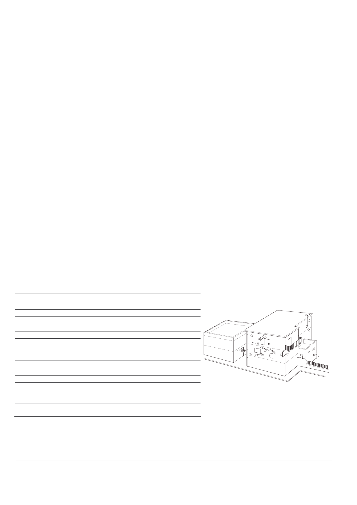
POSITIONING THE FUME EXHAUST TERMINALS
FORCED FLOW SEALED CHAMBER APPLIANCES WITH CONFIGURATION TYPE C12 B22 B32
Terminal position
A Below a window 600 mm
B Below an air vent 600 mm
C Below the gutter 300 mm
D Below a balcony (1) 300 mm
E From an adjacent window 400 mm
F From an adjacent air vent 600 mm
G From vertical or horizontal pipes or outlets (2) 300 mm
H From a corner of a building 300 mm
I From a recess in the building 300 mm
L From the ground or another walkway 2500 mm
M Between two terminals arranged vertically 1500 mm
N Between two terminals arranged horizontally 1000 mm
O From a front surface facing outwards without apertures or
terminals within a radius of 3 metres from the fume outlet
2000 mm
Fig.4
P From a front surface facing outwards with apertures or
terminals within a radius of 3 metres from the fume outlet
3000 mm
NOTE
1) Terminals below a balcony must be positioned so that the total path of the fumes, from the point at switch they are emitted to the outlet on the
external perimeter of the balcony, is no less than 2000 mm.
2) The terminal must be positioned no less than 500 mm from materials sensitive to the action of the combustion products (for example, plastic
gutters or downspouts, wooden jetties etc.) unless these material are adequately screened.