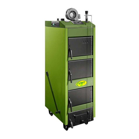
SAS Agro Eco Installation guide

Operation and Maintenance
DOCUMENTATION
for SAS AGRO-ECO boiler for a water-based
central heating system, biomass-fired
(pellets, oats, dry fruit stones, etc.)
SAS
AGRO
ECO
BOILER

TABLE OF CONTENTS
page
Declaration of Conformity 3-4
Test certificate for the "eco safe mark" 5
1. Preface 6
2. Intended use of a boiler 6
3. Boiler design and operation 7
4. SAS AGRO-ECO boiler equipment 14
5. Technical and operational parameters 23
6. Fuel 23
7. Boiler installation guidelines 30
7.1. Boiler room requirements 30
7.2. Noise and noise reduction methods 31
7.3. Boiler placement 31
7.4. Boiler stack connection 33
7.5. Boiler connection to a heating system 34
7.5.1. Open vented system 35
7.5.2. Sealed system 37
7.6. Boiler connection to a power supply system 42
8. Guidelines for use and operation 43
8.1. Filling with water 43
8.2. Boiler firing and operation 45
8.2.1 Boiler firing in an automated mode 45
8.2.2 Boiler firing and operation in an "emergency burning" (steel grate) 48
8.3. Boiler cleaning 48
8.4. End of burning 49
9 Conditions for safe operation 50
10. Operation and maintenance of a feeder and a burner 51
11. Statuses of incorrect boiler work 52
12. Protective devices 54
13. Delivery terms and conditions 57
14. Boiler disposal 58
15. Warranty terms and conditions 59
Service repairs 62
Warranty card 63
LIST OF FIGURES AND TABLES
Table 1 Equipment for a SAS AGRO-ECO boiler
15
Table 2 Spare parts catalogue – ceramic panels
16
Table 3 Technical and operational parameters for a SAS AGRO-ECO 17-48 kW boiler
24
Table 4 Technical and operational parameters for a SAS AGRO-ECO 58-150 kW boiler
25
Table 5 Basic parameters of pellets for SAS AGRO-ECO boilers
29
Figure 1 Flue gas temperature sensor installed in a flue
8
Figure 2
Location of a temperature sensor with a capillary tube– thermal protection sensor
9
Figure 3 Moving grate positioning sensor (Hall effect sensor ).
11
Figure 4 Connection terminal strip supplying control equipment
12
Figure 5 Module controlling burner operation
12
Figure 6 Construction diagram of a SAS AGRO-ECO 17-48 kW boiler
26
Figure 7 Construction diagram of a SAS AGRO-ECO 58-150 kW boiler
27
Figure 8 Installation of adjustment feet in a SAS AGRO-ECO boiler
32
Figure 8 General connection diagram – an open vented system with a four-way valve
38
Figure 10 General connection diagram – an open vented system with a plate exchanger
39
Figure 11 General connection diagram – sealed system
40


Central heating boiler with automated fuel feeding
SAS AGRO-ECO
heat output from 15 kW to 50 kW
Directive 2006/42/EC
(Journal of Laws
No. 199/2008, item 1228)
(MD) Machinery Directive
Directive 2004/108/EC
(Journal of Laws
No. 82/2007, item 556)
(EMC) Electromagnetic compatibility
and harmonised standards:
and the European Norm
This is confirmed with the mark
placed on the device
The declaration for the above-mentioned product shall become invalid
when any design changes are introduced to it without manufacturer's consent.
Should the title to the device be transferred on another person,
this declaration should accompany the boiler.
Owner: Mieczysław SAS
Busko-Zdrój, July 14, 2014
declares hereby,
assuming full responsibility, that the product:
conforms to provision of:
DECLARATION OF
CONFORMITY CE
Mieczysław Sas
PN-EN ISO 12100: 2012
PN-EN 61000-6-2: 2008P
PN-EN 61000-6-3: 2008P
PN-EN 303-5: 2002
Manufacturer company seal


6
1. PREFACE
Dear Buyer and User of a SAS AGRO-ECO boiler, This operating and main-
tenance manual contains all necessary information for energy-efficient, safe and
long operation of your boiler.
The device is delivered together with a set of operating and maintenance man-
uals for operation of the boiler and its controller.
Before installation and operation of this device you must read and under-
stand contents of this operating and maintenance manual.
After acquainting with this manual you will be able to use this device in an op-
timum way. By becoming thoroughly acquainted with this manual you will be able
to operate the boiler in an effective and safe way.
Boilers manufactured by the Metal Products and Boiler Production Plant "SAS”
meet the requirements of relevant EU directives and are CE-marked, and this is
confirmed in the enclosed EC DECLARATION OF CONFORMITY.
THIS DOCUMENTATION SHOULD BE KEPT FOR A FUTURE USE, AND IT
IS ALSO A WARRANTY CARD FOR THE BOILER.
2. INTENDED USE OF A BOILER
SAS AGRO-ECO boilers with a fuel tank and an automated feeder are desig-
nated for water central heating systems, open vented or sealed*, with gravita-
tional or forced water flow, secured according to current specific national or EU
regulations (PN-EN 12828+A1:2014-05 Heating systems in buildings. Design for
water-based heating systems). They are recommended, in particular, for heating of
residential flats in one-family or multi-family houses, commercial, services, cater-
ing and workshop facilities, etc., in which water supply design temperature does
not exceed 85 °C, and working pressure does not exceed 1.5 bar. Required hot
gas pass 0.30 – 0.55 mbar, depending on the device output (according to PN-EN
13384-1:2015-05 Chimneys. Thermal and fluid dynamic calculation methods. Part
1: Chimneys serving one heating appliance).
These boilers may also work with domestic hot water systems through a heat
exchanger of any producer that meets current standards. The boiler cannot be
used as a continuous flow water heater. The SAS AGRO-ECO boiler is also not
intended to be used as an air heater.
A boiler for heating a building should be selected on a basis of an energy heat
balance of that building, developed in accordance with specific current national
or EU regulations (PN-EN 12831:2006 Heating systems and water based cooling
systems in buildings – Method for calculation of the design heat load).
* the installed system must meet specific requirements of standards in force in a country of destination concerning safety
devices for water-based heating equipment in open vented systems,and expansion vessels in an open vented or sealed
systems (concerns boilers of up to 100 kW) together with accessories: diaphragm expansion vessel, pressure relief
valve, equipment for control and measurements, or devices for removing excess heat.
*) inner partitions (components in contact with fire) are made of 6 mm thick boiler plate steel P265GH (8 mm thick plate
boiler steel 16Mo3 for boilers exceeding 78 kW); the external shell of the water jacket is made of 4 mm steel plate (5 mm
for boilers exceeding 78 kW).
1. PRELIMINARY

7
NOTE 1:
The boiler should be installed and operated only in conditions meeting those
specified in the operation and maintenance manual (manufacturer documen-
tation delivered together with the device)!
NOTE 2:
Any changes in the design aiming at adapting the boiler to perform functions
not intended by its manufacturer are strictly forbidden and result in a loss of
warranty rights and documents associated with the product!
3. BOILER DESIGN AND OPERATION
The SAS AGRO-ECO heating boiler is a low temperature central heating boiler
adapted to high performance, fully automated firing of biomass in form of
wood granulate (pellets of parameters specified according to EN 14961-2) and
oats. Biomass other than wood , in form of dry fruit stones (e.g., sweet cherry,
cherry, etc.) can be used as alternative (substitute) fuel, of parame-ters
conforming to EN 14961-6, see Chapter 6 "Fuel".
Basic boiler components are listed in Fig. 6 and Fig. 7.
The boiler consists of a body constructed of welded steel plates*), and pipes.
The boiler water jacket forms a double-walled cuboid divided with water partitions.
The furnace chamber is located under a high-performance convection heat ex-
changer.
With the boiler structure based on three-pass layout of a flue gas duct, flue gas
heat is fully recovered. Also the upper part of the furnace chamber is closed with
a water jacket.
Flue gases are directed to a stack through a flue located in the upper part of
the boiler.
A clean out door, a firing/feed door and an ash box door are installed on a front
wall of the boiler. The front clean out door and the firing/feed door provide access
to the furnace chamber for maintenance operations and periodic cleaning of con-
vection ducts of the boiler. The ring/feed door is also used for manual (emergen-
cy, e.g., lighter failure) firing of the boiler in the automated fuel feeding mode and
can be used as a feed door to stack the boiler when it is operated in the "emergen-
cy" mode (fuel burned on the steel grate). The ash box door is provided with a flap
in its bottom part, dosing air flow into the "emergency" burning process. The door
of a side clean out hatch is used to remove ash formed during furnace operation.
The whole heat exchanger structure is covered with an insulating material in
form of mineral wool, filling the space between the exchanger and the boiler cas-
ing.
NOTE:
The flue gas temperature (semiconductor PT1000) sensor is installed in the flue,
controlling the burning process and reducing stack losses (controlling a blower
fan) A terminal block facilitates its quick and easy replacement, whenever neces-
sary (see Fig. 1).

8
NOTE:
For correct operation of a controller controlling the burning process – work of the
automated fuel feeding system – periodic cleaning of dust and soot deposits from
the sensor surface is recommended.
Due to an overpressure in the whole inner space of the boiler, it is provided
with fire doors and inspection hatches with circumferential sealing (ceramic rope,
gaskets) and screwed connection, ensuring for its tight closing. Furthermore, it
is also provided with adjustment systems for hinges, and for closing systems for
doors and a fuel tank cover.
Non-flammable insulating materials were installed to reduce heat losses and
secure against excessive increase in a temperature of external boiler surfaces. The
heat exchanger surface is insulated from the environment with external cladding
of powder-coated steel sheets, under which a thermal insulation layer of asbes-
tos-free non-flammable mineral wool is installed. The insulating material tightly
fills space between the exchanger and the boiler casing (powder-coated external
insulation metal sheet). Boiler doors are insulated, reducing heat losses. Door or
clean out hatch handles are made of non-flammable components significantly re-
ducing heat transfer, Mobile components (gearmotor, gear wheels and chain sys-
tem driving the fuel feeder, mobile grate drive, blower fan) located under a hopper
are secured against direct access with additional removable covers. Furthermore,
for safety reasons, a pictogram informing a user about presence of the mobile
components was used.
*) fuel parameters specified in the standard DIN 51731, diameter 6–8 mm, length 20–30 mm, max. water con-
tent 12%, do not use fuel of granulation coarser than specified, as such fuel may hinder the feeder operation.
In particular, during fuel loading or replenishment attention should be paid to undesirable objects or stones that may
block feeder mechanism.
**) inner partitions (components in contact with fire) are made of 6 mm thick boiler plate steel P265GH (8 mm thick plate
boiler steel 16Mo3 for boilers exceeding 78 kW); the external shell of the water jacket is made of 4 mm steel plate (5 mm
for boilers exceeding 78 kW).
Figure 1 Flue gas temperature sensor installed in a flue

9
The fuel tank is provided with a loading opening with sealing and a closing
system. The design of the tank equipped with the hopper ensures free transport of
fuel (gravitational discharge).
Additional protection against flashback was installed in form of a pressure
equalising system in the hopper, which is also used for drying and ventilation
(preventing corrosion).
A hot water connector is welded to the upper part of the exchanger, while a re-
turn water connector is welded to a bottom part of
the side wall. A discharge connector is located on
a side wall in the bottom part of the boiler. It is also
used for connection of cooling water (from a water
supply system) when overheat thermal protection
– a thermostat valve (a device removing excess
heat, according to Fig. 10 and Fig. 11) is installed.
A connector (G 1/2”) for a temperature sensor
with a capillary tube, L=150 mm, is installed on
the side wall in the upper part of the boiler, see
Fig. 2 (excluding boilers above 100 kW).
The fuel hopper (tank), together with the feeder drive mechanism and the
blower fan, is installed in the back part of the boiler, behind its body.
Adjustment feet with the adjustment range of 30 mm ensure the boiler final
alignment versus the floor. The user is responsible for possible installation of ad-
justment feet, according to guidelines provided in this instruction (Fig. 8).
A characteristic feature of SAS AGRO-ECO boilers is an automated high-per-
formance self-cleaning furnace burning precisely the amount of fuel necessary
to obtain the temperature set on a controller by the user. Furnace components
exposed to high temperatures are made of stainless steel and ceramic mate-
rials. Ceramic panels used in the furnace ensure optimum conditions for
biomass burning (an optimum temperature for oats burning is 1200 °C) and
increase fur-nace effectiveness, while they have a positive effect on its life.
Fuel from a tank is fed automatically with a screw conveyor (a system with two
screws and a transfer duct).
The funnel-shaped fuel tank ensures gravitational fuel transport through a load-
ing opening from a fuel tank to an upper fuel feeding pipe with a screw installed,
then fuel is transported gravitationally through a transfer duct to a lower distribu-
tion pipe in which the second screw is installed. With this screw fuel is supplied
to the furnace chamber. The screws are rotated by gear wheels driven by a chain
driven by a gearmotor. Safe fuel transport between the upper screw, the bottom
screw and the furnace chamber is only possible due to correctly selected number
of teeth in transmission wheels. All processes leading to burning of supplied fuel
in air supplied with the blower fan installed under fuel tank casing take place on a
Figure 2 Location of a temperature sensor with
a capillary tube– thermal protection sensor

10
grate in the furnace chamber. The supplied air is separated in the air chamber. The
initial air is supplied under the grate, while the secondary air is pumped through
a system of nozzles in ceramic panels into the fuel burning zone. The appropriate
– depending on a type of burned fuel – stream of air supplied by the blower fan is
controlled with a manual knob located on the boiler side wall.
The furnace grate is divided into a fixed part and a section of moving fire bars.
The cyclically activated moving grates driven by an eccentric mechanism remove
fuel burning residues, i.e., ash, particularly in form of sintered slag, from the fur-
nace space to the boiler chamber. This solution maintains the furnace space of
the burner in a "clean" condition without interrupting the continuity of the burning
process. After a clean out cycle the moving grates are placed in slots of the lower
part of the furnace. The grate is positioned with a position control sensor (Hall
effect sensor, see Fig. 3, Fig. 6 and Fig. 7).
Figure 3 Moving grate positioning sensor (Hall effect sensor ).
NOTE:
Correct operation of the moving grate mechanism requires a correct setting of
the Hall effect sensor. A distance between the position sensor and the wrapping
connector of the moving grate should be 3 to 5 mm, these components should be
aligned axially.
The fuel feeder design developed at ZMK SAS, using a set of two screws,
is protected by an application No. W.120870 issued by the Polish Patent Of-
fice.
Additionally, for easier operation the boiler is equipped with a ceramic heater,
firing fuel during the boiler start-up (fuel self-firing). An automatic fuel firing and a
system to maintain flame after the set temperature is reached ensures an efficient
operation of this boiler even during periods of low demand for heat (an option
for continuous operation or operation with a domestic hot water tank during the
summer).

11
A microprocessor controller automatically controls operation of the fuel feeder,
the blower fan, the fuel igniting heater and the furnace cleaning mechanism.
During the final phase of biomass burning, a residual negligible non-flammable
part of fuel – ash – is transferred to the ash box chamber equipped with a remov-
able ash drawer that should be emptied periodically (ash resulting from biomass
burning can be used as valuable ecological fertiliser for soil enrichment).
An efficiently working boiler furnace burns the amount of fuel necessary to
maintain the temperature set on the controller by the user. Thus, the controller
continuously measures a temperature of water in the boiler, and on this basis ap-
propriately controls operation of the boiler operational components. At the same
time the controller controls operation of pumps: central heating, domestic hot wa-
ter, floor, and circulatory (when the heating system is equipped with pumps). In a
system equipped with a mixing valve with a cylinder, the mixer can be controlled
directly from the boiler controlled. Connection points for circulatory pumps, tem-
perature sensors and the mixer are located on the boiler side wall (see Fig. 4, Fig.6
and Fig. 7).
The module (see Fig. 4, Fig.6 and Fig. 7) controlling furnace operation is lo-
cated under the insulation upper lid. The module controls the fuel igniting heater
and the mechanism for furnace cleaning together with the positioning sensor (Hall
effect sensor). The temperature controller installed on the boiler controls operation
of the blower fan, the fuel feeding mechanism, and the feeder temperature sensor.
Cooperation between the module (Fig.6 and Fig. 7 item 32) controlling the burner
and the main boiler controller (Fig.6 and Fig. 7 item 14) is possible due to RS-
based wired communication.
Figure 4 Connection terminal strip supplying control equipment
(note: the photograph shows an example of connection layout, details are provided in the controller operation and
maintenance manual).

12
The boiler controller* is also adapted to operation with a room temperature
controller.
Advantages of the boiler include its simple operation in form of periodic sup-
plementing of fuel in the tank (hopper: every 1 to 3 days, depending on weather
conditions and building insulation) and removing of ash from the ash drawer with-
out a need to put the boiler off. After firing the boiler does not require continuous
operation, and apart from periodic planned maintenance, it can be used in general
throughout the heating season. The boiler can also be used outside the heating
season in a system with a domestic hot water tank.
A boiler room with a solid fuel boiler is not maintenance-free and requires
periodic monitoring. During boiler operation certain daily activities must be
performed (e.g., verification of the furnace operation), to prevent emergency
situations.
Generally, the SAS AGRO-ECO boiler is operated automatically (in a con-
tinuous mode) using a unit consisting of the gearmotor-driven fuel feeder, the
self-cleaning blower furnace, and the digital temperature controller.
Additionally, the boiler is adapted to operation in the "emergency burning"
mode, e.g., in the event of power outage or failure of the feeder/fan (see details
in chapter 8.2.2). Then the boiler runs using a natural flue gas flow, therefore, the
boiler operation in this mode does not require any power supply. In this mode a
temperature of water in the boiler can be checked with an analogue thermometer.
The burning process can then be controlled manually with a screw adjusting air
supply in an air-dosing flap. The boiler is equipped with a bracket for installation of
* Detailed description of the controller design, work and operation is provided in the con-
troller operating manual attached to this documentation.
Figure 5 Module controlling burner operation.

13
an emergency steel grate. This grate is not a standard boiler equipment.
It is forbidden to burn plastic materials; this may result in blocking of air
distribution openings and contamination of the furnace plate. Contamination
of the heat exchanger surface leads to reduced boiler efficiency and dete-
rioration in the burning process. It is forbidden to use flammable materials
(such as petrol, kerosene, or solvents) for boiler firing, as this may result in
a fire or explosion.
To ensure safe operation, the SAS AGRO-ECO boiler is equipped with a secu-
rity system consisting of several steps. The protective devices include protection
against flashback into the fuel tank through the fuel feeder (a temperature sensor
in the fuel route), a set of two screws separated with a transfer duct, and a thermal
switch protecting against boiler overheating.
The feeder in the SAS AGRO-ECO boiler, equipped with two transport screws,
consists of two fuel distribution pipes separated with the transfer duct ensuring a
distance between them. Feeders previously available in the market particularly for
biomass, were equipped with a single screw mechanism. This system requires an
additional protective device to be installed, securing against uncontrolled flash-
back to the fuel tank. For this purpose, an extinguishing system based on a ther-
mally activated valve and an external water tank is used. When temperature in the
fuel supply system rises, the valve is opened and water is poured over the furnace.
After this procedure the boiler furnace and chamber must be thoroughly cleaned,
and those operations are very labour- and time-consuming. This mechanism pro-
tects against uncontrolled flashback into the fuel tank in boilers, without a need
to install the extinguishing system. The feeder in the SAS AGRO-ECO boiler was
designed to eliminate a risk of flashback from the furnace chamber to the fuel tank
during the normal operation or the fuel feeder downtime, as well as during power
supply outages (no power supply).
The system monitoring the boiler operating equipment guarantees the boiler
is automatically switched off in the event of the fuel feeder blocking, failure of the
system driving the moving grates, flame extinguishing in the heating chamber, etc.
In the event of power outage the operational status and all controller settings are
remembered, therefore, when the power supply is restored, the boiler is started
automatically, bringing the system to the required temperature.

14
4. SAS AGRO-ECO BOILER EQUIPMENT
SAS AGRO-ECO, the automatic boiler with a control system and a self-clean-
ing furnace is delivered in an assembled state, equipped with a controller, a fan, a
fuel feeder with a gearmotor, a fuel lighter, ceramic panels, a fuel tank, an automat-
ed furnace, and ash-box, feeding-firing, and clean out doors, with thermal insula-
tion of mineral wool, and outer insulation in form of a jacket of powder-coated steel
sheets of high resistance to corrosion. The SAS AGRO-ECO boiler is equipped
with fuel feeder (a system of two transport screws separated with a transfer duct),
and a fuel tank, with a hopper on the left (L) or the right (R) of the boiler (always
in the back). The hopper location should be clearly stated, as it is not possible to
move it to the other side afterwards. The user is responsible for possible installa-
tion of adjustment feet, according to guidelines provided in this instruction.
The digital equipment (control systems) for the SAS AGRO-ECO boiler as
specified in the attached operating manual for the temperature controller.

15
Table 1 SAS AGRO-ECO boiler equipment
Boiler standard equipment
1Boiler operating and maintenance documentation
(operating manual + warranty card) pieces 1
2 Operating manual + warranty card for a temperature regulator (controller) pieces 1
3 Warranty card for a blower fan pieces 1
4
Temperature regulator (controller operating a mixing valve*,
Ethernet module**) together with a module controlling the burner operation
and a set of cables and sensors for the system operation (details in the
controller operation and maintenance manual)
pieces 1
5 Blower fan pieces 1
6 Analogue thermometer pieces 1
7 Fuel feeder with a gearmotor pieces 1
8 Drive motor for moving grates pieces 1
9 Grate position sensor – Hall effect sensor pieces 1
10 Stainless steel biomass furnace with a set of moving grates set 1
11 Feeder temperature sensor pieces 1
12 Flue gas temperature sensor pieces 1
13 Ceramic panels (top/side) set 1
14 Fuel lighter pieces 1
15 Fuel tank pieces 1
16 Moving parts guard (fuel tank casing) set 1
17 Pressure relief valve (2.5 bar) pieces 1
18 Tool kit for boiler operation
(poker, cleaning rod, scraper, ash shovel) set 1
19 Adjustment feet for boiler levelling (excluding boilers above 36 kW) pieces 4
20 Connector (G½”) for the temperature overheating sensor *) pieces 1
Boiler optional equipment
1 Room regulator pieces 1
2 Module controlling an additional mixing valve **) pieces 1
3 Draught regulator (G¾”) with a measuring capillary tube, L=140mm pieces 1
4 GSM module **) pieces 1
5 Ethernet module **) pieces 1
6 Module for heat buffer tank control ** pieces 1
7
Thermostat valve with a capillary tube (G½”) protecting against overheating *)
- open vented system with a plate exchanger (e.g. Regulus, type BVTS)
- sealed system (e.g. SYR 5067)
pieces 1
8 Steel grating for "emergency burning" pieces 1
9Module controlling an external fuel hopper together with a set of fuel
level sensors **) set 1
* controlling two mixers – Recalart MultiFun controller
** concerns boilers with a Recalart MultiFun controller
*) excluding boilers above 100 kW
**) concerns boilers with a TECH ST-450zPID controller

16
The automated boiler SAS AGRO-ECO is equipped with a set of ceramic panels (refractory concrete). Biofuel water content
significantly affects combustion process and achieving a full boiler heating effect. The automated furnace equipped with
ceramic panels ensures optimum conditions for biomass burning, increases burning process effectiveness, and has a
positive effect on the boiler's life.
Ceramic panels are wearable material, subject to regular replacement The order should be placed according to the
product code, as listed below.
Table 2 Spare parts catalogue – ceramic panels
No. Boiler Ceramic panels (dimensions) Name Product code Pcs
(set)
1a
SAS
AGRO-ECO
17/23kW
Upper ceramic panels
for boilers ECO,
AGRO-ECO 17,23 kW
Upper small ceramic
panels for a boiler
AGRO-ECO 17,23 kW
Left side ceramic panels
for the boiler
AGRO-ECO
17, 23, 29, 36 kW
CER-ECO_AGRO
-17_23-G 1
1b CER-AGRO
-17_23-GM 1
1c CER- AGRO-
17_23_29_36-BL 1

17
1d
SAS
AGRO-ECO
17/23kW
Right side ceramic
panels for the boiler
AGRO-ECO
17, 23, 29, 36 kW
Upper ceramic panels
for boilers ECO 29 kW,
AGRO-ECO 29, 36 kW
Upper small ceramic
panels for boilers
ECO 29 kW,
AGRO-ECO 29, 36 kW
Left side ceramic panels
for the boiler AGRO-ECO
17, 23, 29, 36kW
CER- AGRO-
17_23_29_36-BP 1
2a
SAS
AGRO-ECO
29/36kW
CER-ECO_AGRO
-29_36-G 1
2b CER-AGRO
-29_36-GM 1
2c CER- AGRO-
17_23_29_36-BL 1
No. Boiler Ceramic panels (dimensions) Name Product code Pcs
(set)

18
2d
SAS
AGRO-ECO
29/36kW
Right side ceramic
panels for the boiler
AGRO-ECO
17, 23, 29, 36 kW
Upper ceramic panels
for a boiler
AGRO-ECO 42, 48 kW
Left side ceramic panels
for the boiler
AGRO-ECO 42, 48 kW
CER- AGRO-
17_23_29_36-BP 1
3a
SAS
AGRO-ECO
42/48kW
CER-AGRO
-42_48-G 2
3b CER- AGRO
-42_48-BL 1
No. Boiler Ceramic panels (dimensions) Name Product code Pcs
(set)

19
3c
SAS
AGRO-ECO
42/48kW
Right side ceramic
panels for the boiler
AGRO-ECO
42, 48 kW
Upper large ceramic
panels for boilers
AGRO-ECO 58, 68 kW
Upper small ceramic
panels for boilers
AGRO-ECO 58, 68 kW
CER- AGRO
-42_48-BP 1
4a
SAS
AGRO-ECO
58/68kW
CER-AGRO
-58_68-GD 1
4b CER- AGRO
-58_68-GM 1
L P. Boiler Ceramic panels (dimensions) Name Product code Pcs
(set)

20
4c
SAS
AGRO-ECO
58/68kW
Left side ceramic panels
for the boiler AGRO-ECO
58, 68 kW
Right side ceramic
panels for the boiler
AGRO-ECO
Upper large ceramic
panels for boilers
AGRO-ECO
78, 90, 100 kW
CER-AGRO
-58_68-BL 1
4d CER-AGRO
-58_68-BL 1
5a
SAS
AGRO-ECO
78/90/100 kW
CER-AGRO
-78_100-GD 1
No. Boiler Ceramic panels (dimensions) Name Product code Pcs
(set)
Table of contents
Other SAS Boiler manuals
Popular Boiler manuals by other brands

elco
elco Bypass R600 Operation and installation manual

UTICA BOILERS
UTICA BOILERS UB95M-200 Installation, operation & maintenance manual

Strebel
Strebel S-AF Installation & maintenance manual

ATTACK
ATTACK DPX15 Instructions for use

Biasi
Biasi Savio Gaia 424 S installation manual

Bosch
Bosch ZSB 30-2 A Installation and servicing instructions

Hermann
Hermann EURA 23 E quick guide

gledhill
gledhill TEC140-OV Installation & servicing instructions

IDEAL
IDEAL Concord ES140H user guide

Warmhaus
Warmhaus Enerwa Plus 3000 H Installation & user manual

Vaillant
Vaillant GA100CS SERIES Installation and service manual

Airfel
Airfel ECOFEL KB1-24CE Service manual