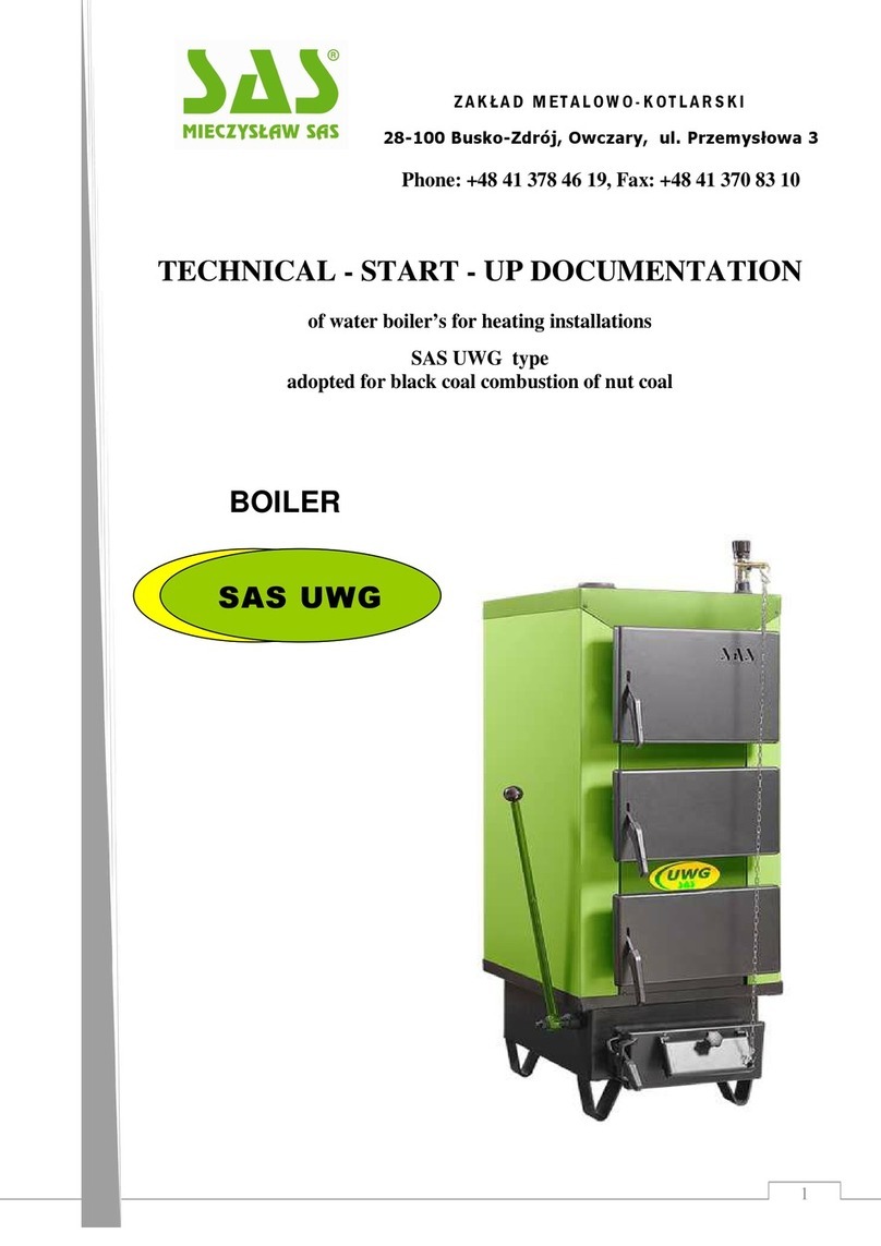
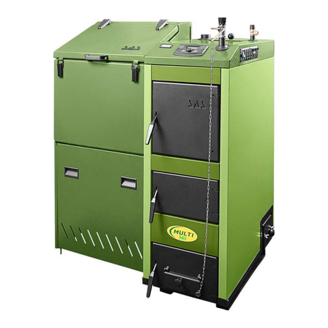
SAS MI Series Operator's manual

1
BOILER
Z A K Ł A D M E T A L O W O
-
K O T L A R S K I
28-100 Busko-Zdrój, Owczary, ul. Przemysłowa 3
Phone: +48 41 378 46 19, Fax: +48 41 370 83 10
TECHNICAL
-
START
-
UP DOCUME TATIO
of water boiler’s for heating installations
SAS MI type
adopted for black coal combustion of fine coal
SAS MI

2
INDEX
page
Conformity declaration 3-4
1. Introduction 5
2. Use of boiler 5
3. Boiler construction description 5
4. Technical data 6
5. Fuel 6
6. Boiler’s assembly guidelines 7
6.1 Requiremends for boiler-room 7
6.2 Boiler’s arragement 7
6.3 Connecting boiler to a chimney 8
6.4 Connecting boiler to a chimney installation 8
6.5 Connecting boilers to electrical installation 9
7. Operation and installation guidelines 9
7.1 Filing with water 9
7.2 Boiler’s firing up 10
Table (technical – exploitation parameters) 11-12
Boiler’s construction scheme 13-14
7.3 Burning 15
7.4 Cleaning the boiler 15
7.5 End of heating season 15
8. Terms of safe exploitation 16
9. States of important boiler’s functioning 16
10. Protection means 18
11. Terms of delivery 18
12. Recycling 18
13. Terms of warranty 19
Service repairs 21
Warranty card 22

3

4

5
Dear buyer and user of boiler of SAS MI type. This technical start-up
documentation contains all necessary information required for energy-saving, safe
and longstanding exploitation of your boiler.
We kindly ask you to get familiar with documentation content prior to
assembling and starting the exploitation of a boiler. Hereby documentation shall be
kept for future use.
Upon familiarization with this manual, the user will be able to utilize this device in
the optimum way. Careful reading of the manual will help in effective and safe
exploitation of the boiler.
Boilers of SAS MI type are designated for water installations of the central heating
systems, open type with gravitational or forced water circulation, protected
according to presently being in force, both domestic or the union detailed
regulations (e.g. PN-91/B-02413 – Boilers of SAS MI type installed in accordance to
hereby documentation recommendations are not subject to the commissioning led
by the Branch Office of Technical Inspection). Boilers are specifically
recommended for the flats heating in single-family homes, pavilions, etc., where
calculated feeding water temperature does not exceed 85°C , and working pressure
does not exceed 1,5 bar. Required gases draught pressure after a boiler is 0,30
- 0,55 mbar (depending on boiler’s power). These boilers may also work in hot
water installations utilizing a heat exchanger.
Boiler’s selection for building heating should be based on heat balance, according to
regulations in force, both domestic and the union (e.g. PN-B-02025:2001).
The heating boiler of SAS MI fine coal type, is a modern construction
heating device with upper combustion, adapted for combustion of black coal
culm type. The boiler is made of steel plates welded type
1
. The front chamber (pos.
4) makes up a furnace with a water grate. Basic boiler’s elements are shown on the
drawing (p. 13). The water jacket (pos. 3) it is a cuboids shape structure with
double walls, separated by water partitions. At the upper part, the furnace is
also closed with water jacket what gives maximum use of gases heat. The
water grate (pos. 10) makes up uniform unit together with a heat exchanger,
1
Internal partitions (elements having contact with fire) are mode of boilerplate 6mm thick. uter body of
water jacket is made of steel plate 4mm thick
1.
I TRODUCTIO
2. USE THE BOILER
3.BOILER CO STRUCTIO DESCRIPTIO

6
so it is not replaceable. Between water grate there are cast iron movable
grates (pos. 11
2
). Under a heat exchanger, on its entire section, there is an
ash pan chamber. There is an opening for combustion chamber cleaning (pos.
24)on the sidewall. At the upper part of boiler, under the cover (pos. 19),
there is a flap of combustion chamber (pos. 20), which during boiler’s work,
transfers gases into a channel placed between water partitions to the smoke
conduit (pos. 21). It also enables easy access to combustion chamber, when
cleaning operations take place. To the upper part of a heat exchanger the
hot water connector is welded (pos. 23). Blowdown connection (pos. 25) is placed
on the lateral wall.
Traditionally, fuel charge door (pos. 5), furnace door (pos. 6), and ash box door
(pos. 8), are placed on the front wall of the boiler. Use of these door enables
easy access when combustion and ash pan chambers cleaning is considered.
Fumes are carried out to a chimney through the smoke conduit (pos. 21)
placed at the back side of a boiler. The smoke conduit is equipped with
mounted smoke throttle (pos. 26), rendering draught regulation. On the smoke
conduit backside, there is a smoke conduit cleaning hole (pos. 22).
The entire heat exchanger’s construction is wrapped with insulation material (pos.
2), a mineral wool, which fill the space between the heat exchanger and boilers
casing (pos. 1).
Water temperature in a boiler may be read by use of the electronic controller (pos.
15), attached to the boiler. Due to simple and proved over many years
design, these boilers are reliable and easily operable.
Operation of boilers is based on forced air admission, what is performed by
platform fan(pos. 16, depending on size, boiler may be equipped with one or
two fans), operated by electronic controller(pos. 15) connected to mains.
Basic energetic parameters are structured in the table (p. 11-12) and on the drawing
(p. 13-14).
Basic fuel for heating boilers of SAS MI type is a black coal for energetic
applications namely fine coal (KL 27/10) with max. humidity of 25% . This
fuel is proper for obtaining the declared power. Application of fuels, other than
recommended, may lead to reduced capacity (heating capacity of boiler) and
reduced time of slow combustion.
2
Does not apply to boilers of power above 36kW
4
.
TECH ICAL DATA
5. FUEL

7
Boiler’s assembling should be performed by qualified and authorized personnel
(qualified person upon adequate training and authorized for performing maintenance
and repair works).
The fitter’s obligation is to get familiar with the product, its functioning and
protection systems functionality.
Prior to boiler’s assembling it is strictly necessary to get familiarized with
the content of hereby Technical-Start-Up Documentation.
6.1REQUIREMENTS FOR BOILER-ROOM
The boiler room, where the heating boiler for central heating installation shall
be installed, must conform the requirements of detailed regulations being in
force, at the country of destination (e.g. PN-87/B-02411).
In particular, the following requirements shall be fulfilled:
the boiler rooms should be located as centrally as possible to rooms
which are covered with heating system, and the boiler itself should be
placed as close as possible to chimney (chimneys),
boiler room entrance door should be opened on the outside, and be made of
inflammable materials,
the boiler room should have air blow-in ventilation, a channel with
section no less than 50% of the chimney section, but not less than
21 x 21 cm, with the exit at the back part boiler’s room , (lack of such
ventilation or obstruction may cause: smoking, inability to get higher
temperature),
the boiler room should have air blow-out ventilation under room’s ceiling
with section no less than 25% of the chimney section, but not less than
14 x 14 cm (the purpose of this system is to carry out harmful gases).
NOTE: Employing of mechanical blow-out ventilation is unacceptable.
The boiler room should be provided with day and artificial lighting.
6.2 BOILER’S ARRANGEMENT
Special foundation for boiler is not required, however it is recommended to put it on
concrete platform 2 cm high, but it may be also practiced to put it directly on
the fire-proof floor. Boiler’s layout should ensure easy and safe operation of
such elements, as furnace, ash box and fuel loading, and do not obstruct
cleaning operations.
The front of boiler should be distant from the opposite wall no less than 2 m,
and similarly, boiler’s sidewalls no less than 0.5 m
6
.
BOILER’S ASSEMPLY GUIDELI ES

8
6.3 CONNECTING BOILER TO TE CHIMNEY
Chimney channel and connection should be performed according to the
requirements of detailed regulations being currently in force in the country of
destination (e.g. Ministry of Infrastructure Decree, as of 1 April 2002 Journal of
acts no. 75).
A boiler should be connected to a chimney with smoke conduit, which is
slightly rising towards the chimney. Smoke conduit length should not exceed 0.5
m. Area of chimney – smoke conduit connection should be precisely sealed.
The chimney’s height and section, as well as accurateness of its construction shall
ensure obtaining required chimney draught of min. 0.30 – 0.55 mbar.
Selection of the chimney’s height and section comparing to boiler power
should be based on detailed regulations being in force in the country of destination.
Assuming that it is not possible to achieve such parameters for chimney, and
chimney draught problems are experienced, resulting in improper boiler
performance, the gases blow-out fan, or chimney base together with built-in fan
may be applied, for supporting and stabilizing the draught. It is important for the
chimney to has its beginning at the level of boiler room floor, for the reason that
gases leaving the boiler are able to be repelled. It is also important, that in the
bottom part of chimney there is washout whole with tight closing.
In order to avoid the air back draught possibly appearing in the chimney, its height
should be above a crest of roof not less than 1.5 m. Chimney’s utility
(permeability) should be checked and confirmed by authorized chimney-sweeper
at least once a year.
PRIOR TO BOILER COMMISSIONING THE CHIMNEY SHOULD BE BASKED!
NOTE: It is recommended that the flue is made of stainless steel material.
Low temperatures in the boiler cause wet gases emission. This may be found as the
reason of wetting and corroding of brick chimneys.
6.4CONNECTING BOILER TO THE HEATING INSTALATION
The boiler should be connected to heat in installation with screw connectors.
Protecting measures for water heating installations of opened type should be
according to detailed regulations being in force in the country of destination (e.g.PN-
91/B-02413).
Volume of pressure vessel should be equal at least 4% volume o water in the entire
heating installation.
NOTE: Ascending and descending safety pipe as well as circulation pipe must
not be equipped with any valves. In addition, those pipes and the pressure
vessel should be protected against freezing.
Boilers of SAS MI type may work with gravitational or forced water circulation. If
installation is provided with circulation pump, than on feeding/return pipe the
differential valve should be installed. When blackout or pump malfunction occurs, this
valve will open and the system start work running by gravitation.

9
NOTE: It is recommended to connect the boiler to heating system provided
with three- or four-pass valve. The main advantage of such connection is boiler
protection function against low temperature corrosion, preventing it from
premature wear.
If not satisfactory to comply with manufacturer’s recommendations in reference
to maintaining given heating water temperature ranges occurs (table TECHNICAL
– EXPLOATATION PARAMETERS p. 11-12, point 12, 13 it concerns in particular
long-lasting return water temperature below 55°C), then the boiler should be
connected to the heating installation equipped with three- or four-pass valve protecting
it against low temperature corrosion.
6.5. CONNECTING BOILER TO ELECTRICAL INSTALLATION
Boiler room should be equipped with electrical installation 230V/50Hz should
be according to detailed regulations being in force in the country of destination.
Electric socked should be earthed. Grounding functionality should be checked.
Cable extensions are forbidden. Faulty installation may cause the controller to be
destroyed or be unsafe for the user. Controller and other cooperating devices are
powered with 230 V, therefore all connections shell be made by qualified
personnel (certified electrician).
NOTE: Electrical cables of powered devices should be placed away from
boiler’s parts, which tend to be hot during exploitation of boiler ( cover
of the upper washout hole, smoke conduit, door).
7.1. FILING WITH WATER
Boiler and the entire installation water filling is to be performed using blowdown
connection.
This activity should be performed slowly allowing the air residing in the
installation to be removed. It is accomplished when water is going out of
overflow pipe. When filling the heating system installation with water it is
recommended to loose screw connection at the place of boiler – installation
assembly (on the hot water connector). Once water is flowing out, tight the
connection.
NOTE: Filling installation with water when boiler is in use, especially if it is
very hot is strictly forbidden, as boiler’s damage or fracture may be caused.
Once heating season is over do not get rid of water from heating installation and
boiler. When required, water may be let of through blowdown connection to a drain
once it is cooled down.
7
.
OPERATIO A D EXPLOITATIO GUIDELI ES

10
7.2. FIRING UP A BOILER
Firing up a fuel in boiler should be started when checked if heating installation is filled
with water, and water is not frozen. It should also be checked, if water is not leaking
through thread fittings on boiler. Do not forget to heat the chimney prior to the firs
startup.
Before firing up a boiler it is necessary to close furnace and ash box door, than on
the surface of the fine coal already placed in the furnace (filled up to the edge of the
chute) put pieces of crumpled paper, and then pieces of wood on top of it. Fire it
up, close chute door, switch on the controller and set the required temperature.
NOTE: Person operating the boiler should know that some of boiler’s
areas are hot, therefore protective gloves should be worn! The same applies
to protective goggles.
Fuel combustion process is regulated by controller, as well as the process of
forced air delivery into combustion chamber. Next fuel application takes place
provided previously introduced fuel is completely burned out and furnace is
cleaned.
During fire up process the boiler should be monitored until it gets
feeding water temperature of 45°C. It is import ant, as varying fuel quality
may cause the boiler to go out.
In case of fire in boiler went out during fire up operation a furnace must be
cleaned, boiler’s should be ventilated and fire up should start again.
During the process a smoking or sweating of boiler may occur. Once boiler and
chimney duct get hot, those adverse phenomena should go away.

11
* when working at average load (50% of rated power)/ rated load
** if manufacturer recommendations regarding heating water temperature ranges are
not observed, boiler
must be obligatory connected to central heating system e uipped with three- or four – ways valve, protecting
against so called „ low temperatures corrosion”
No.
Parameter Unit SAS MI
1.
Boiler power
kW
12
,5
14
17
23
29
36
42
48
2. Boiler heated surface m
2
1.0 1.2 1.5 2.0 2.5 3.0 3.5 4.0
3.
Boil
er efficiency
%
79,0 ÷ 83,1
4.
Fuel consumption *
kg/h
2,0
2,5
2,8
3,2
4,0
4,4
4,7
5,0
5. Load chamber capacity
dm
3
kg
60
~50
70
~60
80
~70
95
~80
110
~95
145
~120
175
~150
200
~180
6.
Exhaust temperature
°C
90 ÷ 210
7.
Boiler water capacity
l
66
74
84
92
102
110
120
130
8.
Boiler weight (without water)
kg
325
345
385
410
455
500
540
580
9.
Re uired chimney draught
mbar
0,30
0,45
10.
Maximal allowable operating pressure
bar
1,5
11.
Maximal allowable working temperature
°C
85
12.
Recomm
ended heating water working temp.
°C
60 ÷ 80
13.
Minimal return water temp.**
°C
55
14.
Power supply
V/Hz
~230 / 50
15.
Power consumption
W
to 110
to 215
16.
Dimensions
A
mm
1185
1235
1235
1235
1235
1285
1335
1335
A1
900
910
910
910
910
960
96
0
960
B
515
515
585
655
725
725
755
755
B1
455
455
525
595
665
665
735
735
H
1070
1110
1110
1110
1160
1220
1220
1320
H1
1040
1080
1080
1080
1130
1190
1190
1290
H2
350
350
350
350
350
350
350
350
H3
790
790
790
800
850
940
940
1030
C
450
500
500
500
500
550
550
550
C1
195
220
220
220
220
240
240
240
D
570
610
610
610
660
740
740
840
17.
Smoke conduit diameter
mm
Ø160
Ø160
Ø180
Ø
20
0
Ø22
0
Ø2
2
0
Ø220
Ø220
18.
Connector pipe diameter (supply/return)
"
G 1½
G 2
19.
Load door opening
mm
x
mm
280x170
280x170
340x170
340x170
340x170
340x1
70
340x170
340x170
20.
Minimal chimney height
m
7
8
9
10
21. Re uired chimney dimensions/diameter
cmxcm
mm
16x16
Ø180
17x17
Ø200
18x18
Ø210
20x20
Ø220
21x21
Ø240
22x22
Ø250
25x25
Ø280
25x25
Ø280
TECH ICAL A D OPERATIO PARAMETER
OF SAS MI
BOILER

12
No.
Parameter
Unit
SAS MI
1.
Boiler power
kW
52
58
62
68
72
78
90
100
110
132
150
175
200
2.
Boiler heated surface
m
2
4.5
5.0
5.5
6.0
6.5
7.0
8.0
9.0
10.0
12.0
14.0
16.0
18.0
3.
Boiler efficiency
%
79,0 ÷ 83,1
4.
Fuel consumpcio
n
kg/h
5,5
8
,
3
4,5
5,0
6,1
7,2
8,3
9,2
10,1
12,3
13,6
15,1
17,2
5. Load chamber capacity
dm
3
kg
160
~135
22
0
~190
180
~140
200
~150
210
~160
240
~180
270
~200
330
~250
350
~260
430
~320
500
~380
550
~410
630
~470
6.
Exhaust temperature
°C
90 ÷ 240
7.
Bo
iler water capacity
l
120
15
0
180
210
245
265
295
345
405
465
510
580
660
8.
Boiler weight (without water)
kg
590
6
1
0
670
800
840
1050
1270
1450
1550
1770
2120
2370
2470
9.
Re uired chimney draught
mbar
0,45
0,55
10.
Maximal allowable opperating
pressure bar 1.5
11.
Max. allowable working temp.
°C
85
12.
Reccomended heating water
working temp. °C 60 ÷ 80
13.
Minimal return water temp.
°C
55
14.
Power supply
V/Hz
~230/50
15.
Power consumption
to 215
to 525
to 750
14.
Dimensions
A
mm
1420
1470
14
70
1485
1485
16
1
0
1680
1740
194
0
2020
20
70
2
28
0
2360
A1
1020
1070
1070
1070
1070
1175
1225
1275
1465
1535
1585
1775
1
82
5
B
725
725
755
795
795
845
895
945
945
995
1045
1045
1095
B1
665
655
695
735
735
785
835
885
885
935
985
985
1035
H
1500
1560
1560
1560
1610
1635
1685
1735
1735
1780
1830
1830
189
0
H1
1470
1530
1530
1530
1580
1605+C*
1655+C*
1705+C*
1705+C*
1750+C*
1800+C*
1800+C*
186
0+C*
H2
350
300
300
300
300
300
300
300
300
300
300
300
300
H3
1175
1210
1210
1200
1245
125
0
128
5
132
0
13
0
5
1325
1355
1345
1
39
0
C
550
600
600
600
6
0
0
65
0
70
0
75
0
80
0
85
0
90
0
9
5
0
100
0
D
670
720
720
720
78
0
7
8
0
82
0
86
0
86
0
90
0
94
0
94
0
100
0
15. Smoke conduit dimensions mm x mm
245x235 245x240 250x250 260x280 265x280 280x290 290x300 300x310 305x320 335x340 345x350 355x360 385x410
16.
Connector pipe diameter
(supply/return) " G 2½ G3 or flange joint
17.
Load door opening
mm x mm
340x200
340x200
340x200
340x200
340x200
340x200
380x240
380x240
380x240
380x240
430x260
430x260
430x260
18.
Minimal
chimney height
m
10
11
1
2
1
4
19.
Re uired chimney dimensions
cm x cm
25x25
2
5
x2
5
26x26
28x28
28x28
28x28
30x30
30x30
30x30
3
2
x3
2
32x32
3
4
x3
4
3
4
x3
4
* when working at average load (50% of rated power)/ rated load
** if manufacturer recommendations regarding heating water temperature ranges are
not observed, boiler must be obligatory connected to central heating system e uipped with three- or four – ways
valve, protecting against so called „ low temperatures corrosion” C* handle use to transport a boiler ( dimension 150 mm)
TECH ICAL A D OPERATIO PARAMETERS OF SAS MI BOILER

13
1. boiler casing (body) 8. ash box door 15. temperature regulator (controller) 22. smoke conduit cleaning hole
2. insulation 9. ash drawer 16. blowing fan 23. return water connector pipe
3. water jacket 10. water grates 17. hot water connector pipe 24. furnace chamber cleaning hole
4. furnace chamber 11. cast iron grates (movable) 18. temperature sensor pipe 25. blowdown connection
5. fuel load door 12. movable grates lever 19. furnace gas chamber cover 26. smoke throtlle
6. furnace door 13. air distribution system 20. furnace gas chamber flap 27. thermometer installation connector pipe
7. glow prevention grid 14. safety valve installation connector pipe 21. smoke conduit
BOILER CO STRUCTIO SCHEME OF SAS MI TYPE
(12,5
–
48 kW)

14
1. boiler casing (body) 8. water grate 14. hot water connector pipe 20. thermometer installation connector pipe
2. insulation 9. furnace chamber 15. furnace gas chamber cover 23. blowdown connection
3. water jacket 10. fuel load door 16. furnace gas chamber flap 24. furnace chamber cleaning hole
4. return water connector pipe
5. ash box door
6. furnace door
7. glow prevention grid
11. front cleaning door
12. blowing fan
13. temperature sensor well
17. smoke conduit
18. smoke conduit cleaning hole
19. smoke throttle
21. temperature regulator (controller)
22. safety valve installation connector pipe
BOILER CO STRUCTIO SCHEME OF SAS MI TYPE
(52
–
200 kW)

15
7.3. BURNING
SAS MI type boiler exploitation is performed based on cycling batching system, what
means, that once the whole bath of fuel placed in a combustion chamber is burned
out and an ash is removed, new charging with fuel takes place and then firing of new
portion of fuel is performed using kindling fuel for supporting this process.
One batch of basic fuel is sufficient for 24 hours, however this time may be extended
depending on heating boiler load. Fuel (fine coal KL 27/10) filling-in and following
firing up activity is carried out trough boiler’s upper door.
In the central heating requirement is changing along with outdoor conditions, e.g.
daytime and temperature. Temperature of water leaving out the boiler depend also
on thermal characteristic of building, e.g. construction materials, in particular the
insulation one. Combustion intensity and heating capacity of the boiler is regulated by
adjusting the temperature will be then displayed on LCD. The controller ensures
optimal combustion process, by regulating fan and circulation pump work. Fan’s
rotational speed depends on measured temperature and parameters setting. Once
fire up process is finished, and boiler riches required temperature, the controller
keeps it constant. If boiler’s temperature is lower than set, rotation speed of fan is
increased, if is higher, scavenges of the boiler are only performed.
7.4.CLEANING THE BOILER
In order to use fuel in the safe manner, and to get declared boiler’s power and heat
efficiency, keeping adequate cleanliness of combustion chamber and convection
channels is indispensable.
As far as furnace chamber of the boiler is considered, special attention should be
paid when removing ash and slag from between grate orifices and chamber’s walls.
Such a cleaning should be exercised prior each boiler’s fire up process, but not
less than after 150÷260 of boiler’s continuous work. Cleaning of convection
channels, with volatile ashes residues, should be performed every 3÷7 days,
depending on quality of burned fuel. The cleaning operation is done through
washout holes indicated on the drawing (p. 12). Once cleaning is finished,
those wholes should be sealed tightly. Cleaning the chimney duct is not less
important.
Air distribution system holes, placed in the interior of combustion chamber are to be
cleaned on routine basis (pos.13). This is highly important to ensure permeability of
the air distribution system supplying the combustion chamber with the air Otherwise,
combustion process may be adversely affected.
7.5. END THE HEATINHG SEASON
Once heating season is finished, or in other cases of scheduled stops, wait
the fuel to be completely burned out. Once boiler is out and cooled down, remove
from the furnace all remains of burned fuel and apply cleaning and conservation of
the entire boiler. Pay special attention to lubricate inner partitions and movable
elements with oil.

16
For the period of brake time, water should not be drained out of boiler and
installation. If boiler’s stopping took place in emergency conditions, glowing fuel
shell be removed into metal box and taken out of boiler room, or alternatively the
gloving fuel may be covered with sand.
NOTE: it is not allowed to put out the fire with water when in the boiler’s room
In order to maintain safe operation of boiler following rules need to be exercised:
keep the boiler in good technical condition and its installation, in
particular take care of the installation tightness, as well as keep sealed
door and washout openings,
keep boiler room tidy, do not stack any objects not related to boiler’s
operation,
in the winter time do not apply brakes in heating process, preserving water
in installation against freezing. Especially, if the safety pipe is frozen
(overflow pipe) it may be very dangerous because of potential damage
of boiler,
it is forbidden to fire up a boiler by use of petrol, kerosene,
solvents, explosion may occur causing he operator to be burned
in case of installation malfunction and lacking water in a boiler do not fill it
in, if boiler is hot, as it may cause its damage
pay attention on power cables used for supplying different appliances, and
take proper care to keep them far away from the boiler, as components
reach high temperatures in course of exploitation (upper washout hole,
smoke conduit,door),
all defects of boiler should be immediately removed.
NOTE: The boiler should be regularly cleansed from soot and tarry residues
– any residue on the convection channels walls disrupts proper heat
transfer from the exchanger, lowering this way efficiency of device and
increases fuel consumption
PROBLEM CAUSE/ SYMPTOM REMEDY
Low heat capacity
of device
gases channels
obstructed clean the channels through
washout holes
lack of fresh air
delivered to boiler
room
check blow-in ventilation,
improve its permeability
8. TERMS OF SAFE EXPLOINATION
9
.
STATES OF IMPROPE BOILER’S FU CTIO I G

17
burning inadequate
fuel apply proper quality fuel (see
chapter "Fuel" p. 6)
boiler power not up to
heating area
improper design and
erection of heating
installation
Improper functioning of
controller, fan adjust controller’s settings up
to
weather conditions or quality of
fuel, if controller does not work
properly consult manual
Smoking
chimney draught not
sufficient check chimney’s permeability
and its parameters (see tab.
height and section to boiler’s
power p. 8), check if chimney
end is not lower than roof
ridge
gases channels dirty clean up boiler through
washout holes
sealing rope indoor
and washout openings
worn
replace a rope (to be replaced
regularly)
improper assembly of
boiler and
chimney connection
check accurateness
very low atmospheric
pressure
improper position of
smoke throttle adjust sprocket position if it is
closed to much
Sudden temperature
and pressure rise installation valves
closed open the valves
pressure vessel frozen
heat the pressure vessel
Water licking out of
boiler so called. "boiler’s
sweating", this is
natural process caused
by temperature
difference in boiler
during boiler’s start-up and
after each standby "heat the
boiler" e.g. burn it up to 70°C
and keep that temperature for
several hours
"Hitting, shooting"
in boiler air in the heating
installation and boiler
due to improperly
performed filling in
process (see chapter
7.1. p. 9)
"heat the boiler" e.g. burn it up
to 70°C and keep that
temperature
for a longer time, till the whole
air is removed from boiler
remove the air from
installation by opening the
valves on radiators.

18
In order to ensure the failure-free and safe operation (to maximum extent) the
controller of boiler is provided with many protection functions. If faulty status is
discovered, the alarm is launched (acoustic signal), and a message is shown on
display (depending on controller version).
TRMAL PROTECTION
The controller is equipped with safety temperature limiter, preserving the boiler
against overheating (boiling water in installation), if the controller is damaged.
Temperature limiter makes up mechanical protection measure, which bimetallic
sensor (placed at the boiler water temperature sensor) is cutting off power supply to
blow-in fan, if temperature is higher than 90°C (p ump still working).
TEMPERATURE PROTECTION
The controller is equipped with additional temperature protection (electronic one),
for the case of bimetallic sensor is faulty. If temperature of 95°C is exceeded, cutting
off power supply to blow-in fan is executed.
SAFETY VALVE
The boiler is equipped with connector for adapting a safety valve, being an
additional protection against pressure raise due to water freezing in part of
installation, especially in the pressure vessel. The safety valve is not supplied with the
boiler.
Commercially delivered boilers are assembled and supplied with complete set
of tools for maintenance together with the technical-start-up documentation.
Before connecting a boiler to a heating installation, make check if all boiler’s
components are in good working condition, and that the boiler is fully equipped.
NOTE: Boilers need to be transported in the vertical position!
In order to recycle the boiler worn device deliver to specialized recycling unit,
according to detailed regulations being in force in the country of destination.
10
.
PROTECTIO MEA S
11
.
T
ERMS OF DELIVERY
12
.
BOILER’S RECYCLI G

19
1. Manufacturer grants warranty for proper functioning of the heating boiler SAS
MI, what is confirmed with t
he stamp of factory.
2. Manufacturer grants warranty for efficient the boiler installed and operated
according to all terms and recommendations included to Technical -Start-Up
Documentation (TSD).
3. A buyer gets together with terms of warranty hereby Technical-Start-Up-
Documentation (TSD), which is laid down rules for the proper operation and safe
exploitation of the heating boiler. Hereby documentation (TSD) must be reading
careful and it is obligatory.
4. Warranty terms are binding from the date of the purchase for the period of:
a. 4 years * for efficient functioning of the boiler,
b. 2 years on the heat protective grate,
c. 2 years on electronics and automation components mounted on the boiler and
produced by other manufacturers:
•controller
•blowing fan
5. Warranty does not cover consumable items:
•sealant (rope)
•sensors
6. Manufacturer is obligated to carry out the charge free repair under warranty in time
period of 14 days starting from the date of a
pplication (done by user).
7. Boiler’s repair, the construction or insulation alterations made by user or other third
parties – will cause the warranty to be invalid.
8. Application of reclamation should be addressed at manufacturer.
9. Boiler replacement realized by manufacturer is only possible based o expert
opinion, that repair is not workable.
10. If the advertiser does not allow double-warranty repairs, despite the willingness of
the guarantor to comply with it, is deemed to have resigned from the advertiser
claims contained in the application of reclamations.
11. In case of unfounded service summon, the customer shell pay travelling and
work costs. Before you call service, please familiarize yourself with the chapter
"States of improper boiler’s functioning". We always offer help by telephone.
__________________________
*
boilers of power 48 kW and higher are cover with 24-months warranty
1
3
.
TERMS OF WARRA TY

20
12. Warranty document makes up the only ground for charge free repair.
NOTE: Manufacturer reserves the right to introduce changes in the
construction of the product for modernization purpose. Such changes may
not be reflected in hereby documentation, however basic, described
properties of the product shall be maintained.
Any remarks and questions on boiler’s SAS type exploitation shall be addressed:
ZAKŁAD METALOWO-KOTLARSKI
Owczary, ul. Przemysłowa 3
28-100 Busko - Zdrój
Tel.: 4841/378 46 19 Fax: 4841/370 83 10
http:// www.sas.busko.pl
e-mail:[email protected]
Technical-Start-Up Documentation valid from 03.01.2011
Table of contents
Other SAS Boiler manuals
Popular Boiler manuals by other brands

AER
AER MFC 3000 user manual

Heat-Flo
Heat-Flo 115-ST-C Installation, operating and service manual

CleaverBrooks
CleaverBrooks CFV Startup guide

Johnson & Starley
Johnson & Starley 47-416-14 Installation, commissioning & servicing instructions

Glowworm
Glowworm Hideaway 120 Instructions for use installation and servicing

Rima
Rima RS-05 Installation operation & maintenance

Unical
Unical ALKON 50 c Installation and Servicing Manual

ECR International
ECR International Olsen OLSSC-050 Installation, operation & maintenance manual

Hendi
Hendi 211243 user manual

Lennox
Lennox GWB9 installation instructions

Clyde
Clyde CG Series datasheet

Munchkin
Munchkin Gas-Fired Hot Water Boiler manual