SATA AE5701 User manual

AE5701/AE5702/AE5704
EN
中文 PT JARU KODE ES
使用说明书 \ User’s Manual \ Bedienungsanleitung \ Инструкция по эксплуатации
사용설명서 \ Manual de instruções \ 取扱説明書 \ Manual del uso
气动抽接废油机
Pneumatic Waste Oil Extractor
Pneumatischer Abrollabsauger
Пневматическая машина для откачки и сбора обработанного масла
에어 폐유 펌핑 웨이스트기
Bomba pneumática de óleo para óleo desperdiçado
空気圧廃油抜き取り・集め装置
Máquina neumática de bombeo y recogida de aceite residual
AE5701_AE5702_AE5704八国-200621.indd 1AE5701_AE5702_AE5704八国-200621.indd 1 2020/6/23 19:05:212020/6/23 19:05:21

2 3
AE5701_AE5702_AE5704八国-200621.indd 2AE5701_AE5702_AE5704八国-200621.indd 2 2020/6/23 19:05:212020/6/23 19:05:21

2 3
AE701/AE5702/AE5703
目录
第一章 产品简介 ...........................................................................................4
第二章 系列产品结构和组件结构示意图: ......................................................8
第三章 使用目的 .........................................................................................10
第四章 危险、警告事项 ...............................................................................10
第五章 抽排油使用方法 ...............................................................................10
第六章 接油使用方法 ..................................................................................11
第七章 检查事项 .........................................................................................11
第八章 常见故障及处理 ...............................................................................11
第九章 注意事项 .........................................................................................12
第十章 产品的保修规定 .............................................................................12
ESPT JARUEN DE KO
中文
AE5701_AE5702_AE5704八国-200621.indd 3AE5701_AE5702_AE5704八国-200621.indd 3 2020/6/23 19:05:212020/6/23 19:05:21

4 5
AE5701/AE5702/AE5704
我公司生产的气动抽、接油系列产品,采用压缩空气为动力源,特别适合于有防爆等要求的场所作业。整机密封性好,
抽接油功能可靠,升降杆采用双节可调,操作方便 , 量杯材质有高强度和耐腐性,产品采用偏心接油盘,增大接油区
域面积。抽油时必须针对不同型号的汽车、机械设备的油箱注油孔径选用相应管径的抽油针管,直接从油箱内抽取废
旧机油。
以上机型为 AE5701 结构,仅作参考,其它具体各机型结构有差异。
第一章 产品简介
ESPT JARUEN DE KO
中文
AE5701_AE5702_AE5704八国-200621.indd 4AE5701_AE5702_AE5704八国-200621.indd 4 2020/6/23 19:05:222020/6/23 19:05:22

4 5
AE701/AE5702/AE5703
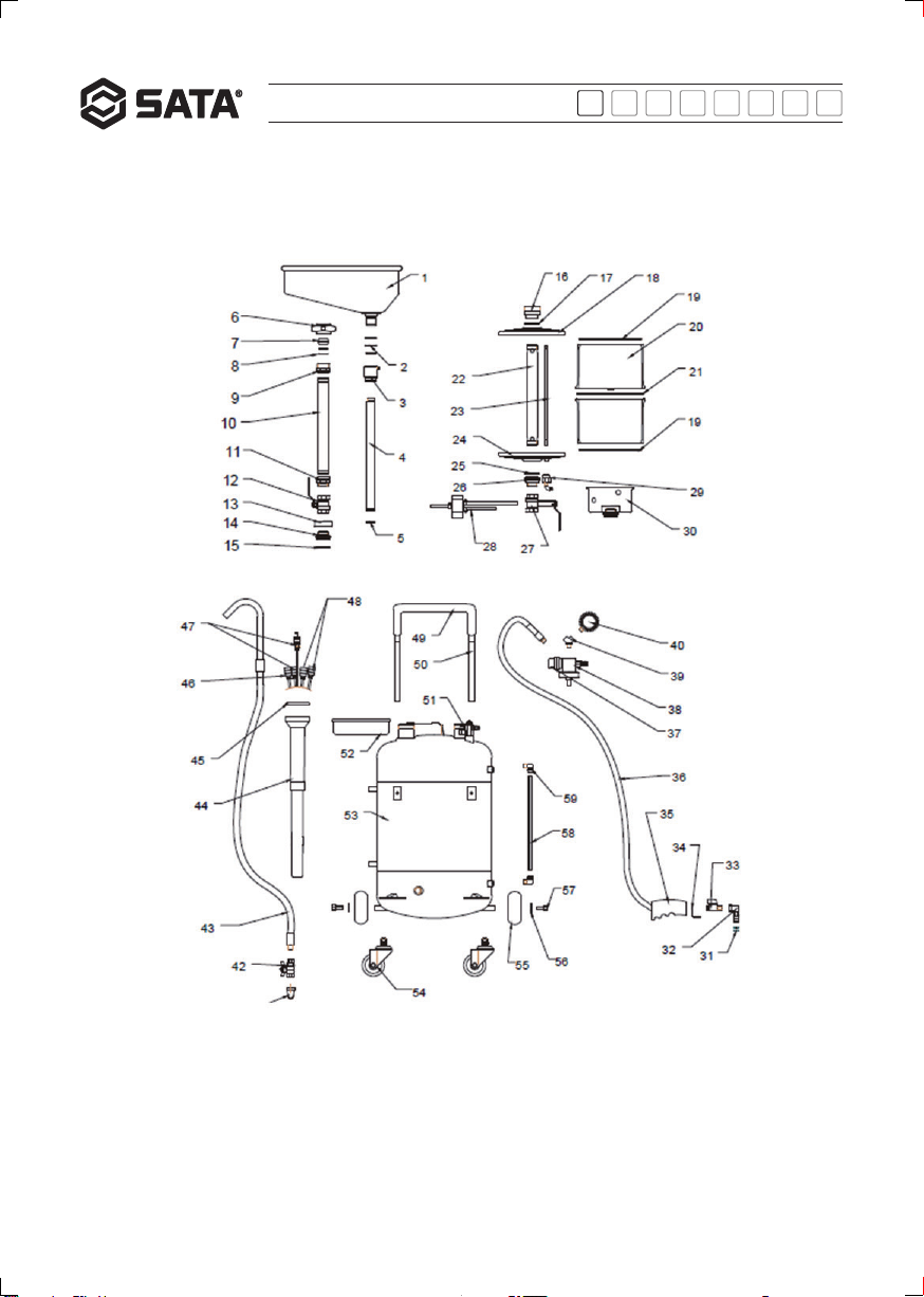
AE5701、AE5702、AE5704 Oil Drainer Parts list
No. Part No. Name No. Part No. Name No. Part No. Name
1 AE5701-5 Oil funnel 21 AE5701-25 O seal ring 41 AE5701-45 Oil draining
bend tube
2 AE5701-6 O seal ring 22 AE5701-26 Central oil
tube 42 AE5701-46 Ball valve
3 AE5701-7 Connecting
nut 23 AE5701-27 Metal air tube 43 AE5701-47 Oil draining
hose
4 AE5701-8 Inner lifting
support 24 AE5701-28 Lower cover 44 AE5701-48 Suction probe
holder
5 AE5701-9 O seal ring 25 AE5701-29 O seal ring 45 AE5701-49 Cover
6 AE5701-10 Locking nut 26 AE5701-30 Lower cover
nut 46 AE5701-50 5 suction
probe
7 AE5701-11 Locking ring 27 AE5701-31 Ball valve 47 AE5701-52 6 suction
probe
8 AE5701-12 O seal ring 28 AE5701-32 Valve part 48 AE5701-53 8 suction
probe
9 AE5701-13 Joint 29 AE5701-33 Air connecting 49 AE5701-54 Handle pad
10 AE5701-14 Outer lifting
support 30 AE5701-34 Valve body
cover 50 AE5701-55 Handle
11 AE5701-15 Joint 31 AE5701-35 O seal ring 51 AE5701-56 Air inflow part
12 AE5701-16 Ball valve 32 AE5701-36 Oil suction
head 52 AE5701-57 Tool tray
13 AE5701-17 Base inner
ring 33 AE5701-37 Ball valve 53 AE5701-58 Oil tank
14 AE5701-18 Nut
connection 34 AE5701-38 Oil suction
hook 54 AE5701-59 Steering
wheel
15 AE5701-19 O seal ring 35 AE5701-39 Handle bar 55 AE5701-60 Directional
wheel
16 AE5701-20 Upper cover
nut 36 AE5701-40 Suction hose 56 AE5701-61 Washer
17 AE5701-21 O seal ring 37 AE5701-41 Silencer 57 AE5701-62 Screw
18 AE5701-22 Upper cover 38 AE5701-42 Generator
part 58 AE5701-63 Level
indicator
19 AE5701-23 O seal ring 39 AE5701-43 T- joint 59 AE5701-64 Bend head
20 AE5701-24 Measuring
cup 40 AE5701-44 Vacuum
gauge
ESPT JARUEN DE KO
中文
AE5701_AE5702_AE5704八国-200621.indd 5AE5701_AE5702_AE5704八国-200621.indd 5 2020/6/23 19:05:222020/6/23 19:05:22

6 7
AE5701/AE5702/AE5704
Dimension:
ESPT JARUEN DE KO
中文
AE5701_AE5702_AE5704八国-200621.indd 6AE5701_AE5702_AE5704八国-200621.indd 6 2020/6/23 19:05:222020/6/23 19:05:22

6 7
AE701/AE5702/AE5703
以下为客户选配件:
1. 耐超高温探针管
3. 延伸接油盘
2. 专用吸油接头
ESPT JARUEN DE KO
中文
AE5701_AE5702_AE5704八国-200621.indd 7AE5701_AE5702_AE5704八国-200621.indd 7 2020/6/23 19:05:222020/6/23 19:05:22

8 9
AE5701/AE5702/AE5704
第二章 系列产品结构和组件结构示意图:
AE5701
AE5702
ESPT JARUEN DE KO
中文
AE5701_AE5702_AE5704八国-200621.indd 8AE5701_AE5702_AE5704八国-200621.indd 8 2020/6/23 19:05:222020/6/23 19:05:22

8 9
AE701/AE5702/AE5703
AE5704
量杯总成:
ESPT JARUEN DE KO
中文
上盖螺母
中心油管
球阀
AE5701_AE5702_AE5704八国-200621.indd 9AE5701_AE5702_AE5704八国-200621.indd 9 2020/6/23 19:05:222020/6/23 19:05:22

10 11
AE5701/AE5702/AE5704
工作原理:利用空气压缩原理,使用特殊设计的真空发生器装置,同时将透明量杯和储油罐内抽真空,产生一定程度
的真空压力差,通过抽油管,将机油抽进透明量杯或储油罐内。然后,在外界空气压力的作用下将罐内废油陆续排到
废油收集容器内。
1)带量杯机型抽真空
使用自平衡量杯抽接油设备,抽真空之前,必须关闭本机器除量杯下部球阀外所有球阀,将经过净化的 压缩空气快速
接嘴接到真空发生器装置前进风嘴处,开始对量杯和罐体同时抽真空(此时,与量杯下方 球阀是否打开无关),抽真
空过程中,仔细观察真空表指针,当指针到达红色刻度区域,之后,切断气 源,完成对透明量杯的抽真空操作。
2)无量杯机型抽真空
关闭所有球阀,将压缩空气接到真空发生器上,对罐体进行抽真空。
3)抽油
a)将本设备移动到需抽油的汽车或机械设备旁,根据需抽油设备的抽油口实际尺寸及其结构选择合适的抽油针管插到
抽油接口处
b)将抽油针管插入待抽吸的油品内部,开启该处球阀, 油品将陆续被抽吸到透明量杯内,吸油完成后及时关闭抽油
管球阀。
4)排油
a)将量杯内所收集的废油排入罐体打开量杯下部球阀,透明量杯内油品将陆续排到储油罐内;
b)将储油罐内的油品排到收集容器内
①自然排油:打开储油罐上除排油弯管处球阀外所有球阀,让罐体内部与外部空气相连,将排油弯管出油口挂到废油
收集容器内,打开罐体下部排油出口处球阀,在大气压力作用下将废油陆续排到收集容器内(排油弯管出口处一定要
低于罐体内液面)
②加压排油:关闭量杯下面球阀,托盘升降杆处球阀,在罐体进气嘴处接入 1bar 压缩空气,将排油管挂于废油收集容
器内,使压缩空气进入罐体;打开排油管下部球阀,在压缩空气作用下,储油罐内废油将陆续被排到废油收集容器内。
(罐体内的压力,超过 1.5bar 时,安全阀自动打开,此时,切断气源)。排油时,请握紧排油管弯钩或固定排油管弯钩。
第三章 使用目的
本产品使用可接收和抽取汽车油箱内的废油两种方式工作,当罐体内废油达到指定位置左右时停止, 最后从罐体下方
的排油管中排出。本产品可移动到指定位置,方便快捷。
第四章 危险、警告事项
1)警告标签的粘贴位置以及内容
使用气动抽接废油机时,请完全按照使用说明书上所注明的安全事项进行操作。 如果安装使用说明书丢失或警告标签
剥落、污损、请务必与销售商联系。 各机器贴有左图所示的警告标签,请确认有无。
2)危险警告事项
2.1 禁止分解
因本产品利用真空压力工作,各部分严格密封,如果随意分解将导致本设备无法工作或引发安全事故。
2.2 请在理解清楚安装使用说明书后使用
如操作有误,有可能会发生意外伤亡事故。
油阀开关标: 加气排油时或罐体内有气压时,请关闭量杯球阀。
量杯警示标:请勿用于抽取刹车油等腐蚀性液体。
第五章 抽排油使用方法
ESPT JARUEN DE KO
中文
AE5701_AE5702_AE5704八国-200621.indd 10AE5701_AE5702_AE5704八国-200621.indd 10 2020/6/23 19:05:232020/6/23 19:05:23

10 11
AE701/AE5702/AE5703
第六章 接油使用方法
第七章 检查事项
第八章 常见故障及处理
将该设备放置在适合位置,调节油盆升降杆适当高度,转动偏心接油盘于放油口下方,打开接油盘下面球阀, 开始放
接油,等到放油完成后,油流进接油盘和罐体中,关闭球阀,设备移开接油位置。
1)工作前检查
每天工作前,关闭所有球阀,对量杯和罐体进行抽真空,然后仔细观察真空表指针的变化,辨别各部件组装处是否有
漏气情况发生。如有请联系销售商解决,以免造成财产损失或人身事故。 注意:抽真空过程中,仔细观察真空表指针,
当指针到达红色刻度区域,切断压缩空气进气源,完成抽真空操作。
2)定期检查
a)漏气检查
b)漏油检查
c)请确认软管接头金属零件是否损坏、变形、磨损以及是否有污渍。
注意:关于定期检查,建议利用专业人员的完整的检查制度。详细情况请咨询销售商。
3)完工检查
作业结束后,将本产品各部位上粘着的污渍(水、杂物、油等)擦拭干净。如发现异常时,立即联系销售商。
4)其它注意事项:
4.1 检查上的注意事项
a)工作前及定期检查,请一定按使用说明书的内容实施;
b)不要将本产品用于与抽接废机油无关的用途。
4.2 使用上的注意事项
a)严禁本产品与火或腐蚀性液体接触;
b)使用时不要超出常用压力范围。
在断定为故障前,请仔细阅读使用说明书,并对照下列检查事项。如仍然处于异常状态中,请联系销售商。
故障 原因 处理方法
真空度达不到
气压不足 调节气流压力使之达到指定压力
量杯破裂 联系销售商更换
真空表损坏 联系销售商更换
除量杯进气口外的球阀未关闭 关闭除量杯进气口外所有球阀
真空发生器损坏 联系销售商更换
抽油速度慢
真空不足 待真空达到指定数值时再使用
抽油针管管接处 O 型密封圈损坏 联系销售商更换
有漏气现象 与销售商联系,在指导下判断漏气部
位
ESPT JARUEN DE KO
中文
AE5701_AE5702_AE5704八国-200621.indd 11AE5701_AE5702_AE5704八国-200621.indd 11 2020/6/23 19:05:232020/6/23 19:05:23

12 13
AE5701/AE5702/AE5704
1)保修规定
在保修期内,并且在完全遵守安装使用说明书、标签上的注意事项进行操作的情况下发生故障时,本公 司有责任进行
无偿修理、调换部件以及寄送更换部件。
2)在下列情况下发生的故障,不属于保修范围之内。
1. 因使用不当、检查、保管等工作疏忽,而发生的故障及损坏。
2. 因随意变更(改造),对产品的构造产生不良作用,因此产生的故障及损坏。
3. 发生因消耗品自然损耗而需要更换的情况。
4. 火灾、地震、风灾水害、其它不可抵抗的外部原因引起的故障及损坏。
5. 因使用非指定的部件引起的故障及损坏。
6. 保修手续不齐全。(例:无型号和机体号码的联络等)
7. 因安装操作的原因产生的故障及损坏。
另外,用于本产品以及其它附件的软管、O 型密封圈、橡胶部件等属于自然消耗品,不属于保修范围之内。
注意:本产品因锈、腐蚀、水等产生的故障不属于保修范围之内
3)保修申请方法
根据上记规定,申请保修请联系销售商。销售商负责必要手续的办理。
另外,保修的一些具体情况,由本公司决定。尽请合作谅解。
4)售后服务
a)状况不良时 请参照安装使用说明书中的[故障和处理]项
b)状况仍不良 根据产品保修规定,请委托销售商负责修理。
c)保修期内的修理 保修期为 1 年,根据产品保修规定提供免费修理。
d)保修期后的修理 请与销售商商谈
如经修理仍能保持产品机能,满足用户要求,提供有偿修理。
关于售后服务详细情况,如有其它不清楚的问题,请咨询询问销售商。
联系时,请告之以下事项。
型号、主机号码(制造号码),购入年月日、故障状况(尽可能详细)。
第九章 注意事项
1)排油时使用的空气压力为 1 bar;
2)透明量杯禁止使用及接触天那水、香蕉水、醛类、酮类等强腐蚀性溶剂;
3)量杯尽量不要集油太满 ( 废油接近 3/4 容积时 ),以免影响抽油速度;
4)当量杯内或罐体内真空压力不足,抽油速度减慢时,可将量杯或罐体抽真空后继续抽油;
5)完成排油工作后,罐体下部排油管出口处球阀必须关闭;
6)对本设备外部的清洁,只能用柔软的抹布和中性清洁,切勿用硬物抹擦或带腐蚀性的和易燃性的液体接触机器表面;
7)使用时,如机器出现异常故障,请速与销售商或厂商联系。
第十章 产品的保修规定
ESPT JARUEN DE KO
中文
AE5701_AE5702_AE5704八国-200621.indd 12AE5701_AE5702_AE5704八国-200621.indd 12 2020/6/23 19:05:232020/6/23 19:05:23

12 13
AE701/AE5702/AE5703
Table of Contents
Chapter I Product Introduction..........................................................................................................14
Chapter II Structure Diagram of Products and Components:.....................................................16
Chapter III Intended Use ........................................................................................................................18
Chapter IV Dangers and Warnings ......................................................................................................18
Chapter V Oil Extracting and Draining Methods.............................................................................18
Chapter VI Oil Collecting Methods.......................................................................................................19
Chapter VII Inspections ...........................................................................................................................19
Chapter VIII Common Faults and Troubleshooting........................................................................... 20
Chapter IX Considerations...................................................................................................................20
Chapter X Warranty ..............................................................................................................................21
ESPT JARUEN DE KO
中文
AE5701_AE5702_AE5704八国-200621.indd 13AE5701_AE5702_AE5704八国-200621.indd 13 2020/6/23 19:05:232020/6/23 19:05:23

14 15
AE5701/AE5702/AE5704
SATA's pneumatic oil extractors are powered by compressed air and particularly suitable for explosion-proof workplace. The equipment
is well sealed and functions reliably. The extension rod is adjustable with two sections and easy to operate. The measuring glass is made
of high strength and corrosion resistant material. The product is equipped with an eccentric oil tray to increase the collecting area. The
extracting tube selected to take waste oil from oil tank must fit the oil fillers on oil tanks of different types of vehicles and mechanical
equipment in diameter.
The figure above is the structure diagram of 97231 series and thus is for reference only. Other models have different structures.
Chapter I Product Introduction
ESPT JARUEN DE KO
中文
AE5701_AE5702_AE5704八国-200621.indd 14AE5701_AE5702_AE5704八国-200621.indd 14 2020/6/23 19:05:232020/6/23 19:05:23

14 15
AE701/AE5702/AE5703
The following options are available for customers:
1. 1. Ultra-high temperature resistant tube
3. Extended oil tray
2. Special oil suction joint
ESPT JARUEN DE KO
中文
AE5701_AE5702_AE5704八国-200621.indd 15AE5701_AE5702_AE5704八国-200621.indd 15 2020/6/23 19:05:232020/6/23 19:05:23

16 17
AE5701/AE5702/AE5704
97232:
Chapter II Structure Diagram of Products and Components:
97231:
ESPT JARUEN DE KO
中文
AE5701_AE5702_AE5704八国-200621.indd 16AE5701_AE5702_AE5704八国-200621.indd 16 2020/6/23 19:05:232020/6/23 19:05:23

16 17
AE701/AE5702/AE5703
Chapter II Structure Diagram of Products and Components:
97234:
97233:
ESPT JARUEN DE KO
中文
AE5701_AE5702_AE5704八国-200621.indd 17AE5701_AE5702_AE5704八国-200621.indd 17 2020/6/23 19:05:232020/6/23 19:05:23

18 19
AE5701/AE5702/AE5704
Pneumatic balancing measuring glass assembly in 3893 structure:
Working principle: Based on the air compression principle, a specially designed vacuum generator is used to vacuum both the transparent
measuring glass and the oil tank such that a certain degree of vacuum pressure difference is generated and the oil will be sucked into the
measuring glass or oil tank through the extracting tube. Then, the waste oil in the tank will discharged into the collection container
Chapter III Intended Use
The product is designed to extract and collect the waste oil from vehicle oil tank. It stops when the waste oil reaches the specified level,
and then the waste oil will be discharged through the drain pipe below the tank. The product can be moved to the specified location in a
convenient and fast way.
Chapter IV Dangers and Warnings
1) Location and information of warning labels
Please operate the equipment in strict accordance with the safety considerations in the Operation Instruction. If the Operation Instruction
is missing or the warning labels peel off or are stained, please contact the distributor. Please check whether each machine is attached
with the warning labels shown on the left.
2) Dangers and warnings
2.1 Do not disassemble the product
All parts are tightly sealed as the product works under vacuum pressure. The disassembly without approval will result in failure or
accidents.
2.2 Please read the Operation Instruction carefully prior to use
Any improper operation may cause casualties.
Warning label on oil valve switch: Please close the measuring glass ball valve during air charging and oil drainage or when there is air
pressure in the tank.
Warning label on measuring glass: Never use it for extraction of corrosive liquids (e.g. brake fluid) are.
Chapter V Oil Extracting and Draining Methods
ESPT JARUEN DE KO
中文
AE5701_AE5702_AE5704八国-200621.indd 18AE5701_AE5702_AE5704八国-200621.indd 18 2020/6/23 19:05:242020/6/23 19:05:24

18 19
AE701/AE5702/AE5703
continuously under external air pressure.
1) Vacuuming of model with measuring glass
Before the oil extractor with self-balancing measuring glass is vacuumed, be sure to close all ball valves except the one below the
measuring glass, connect the quick coupling of the purified compressed air fast nozzle to the air inlet in front of the vacuum generator
to start vacuum both the measuring glass and the oil tank simultaneously, no matter whether the ball valve below the measuring cup is
opened or not. During the process, carefully observe the vacuum meter, and when the pointer falls in the red area, cut off the air supply.
2) Vacuuming of model without measuring glass
Close all ball valves and supply compressed air to vacuum generator to vacuum the oil tank.
3) Oil extracting
a) Move the equipment to the vehicle or machine where oil is to be extracted. Insert an appropriate extracting tube into the oil port
according to the port size and structure
b) Insert the extracting tube into the oil to be extracted and open the ball valve located here to discharge the oil to the transparent
measuring glass continuously. Then close the valve immediately.
4) Oil drainage
a) Drain the waste oil in the measuring cup into the oil tank: open the ball valve below the measuring glass to discharge the oil in the
measuring glass to the oil tank continuously;
b) Discharge the oil in the oil tank into the collection container
①Natural oil drainage: Open all ball valves on the oil tank except the one at the drain elbow to connect the tank with outside air. Put the
oil outlet of the elbow in the container, and open the ball valve at the oil outlet below the tank to drain the waste oil into the container
continuously under atmospheric pressure (the outlet of the elbow must be lower than the oil level in tank)
②Pressurized oil drainage: Close the ball valves below the measuring glass and at the tray extension rod. Supply 1 bar compressed air
from the tank air inlet, put the drain pipe in the container and fill the tank with compressed air; open the ball valve below the drain pipe
to discharge the waste oil in the tank to the container continuously under the action of compressed air. (When the pressure in the tank
exceeds 1.5 bar, the safety valve opens automatically and the air supply is cut off at this time). When discharging oil, please hold or fix the
drain pipe hook.
Chapter VI Oil Collecting Methodsvv
Chapter VII Inspections
Place the equipment properly, adjust the oil tray extension rod to proper height, rotate the eccentric oil tray to the position under the oil
outlet, open the ball valve below the oil tray to discharge oil. After the oil is discharged into the oil tray and the tank completely, close the
ball valve and move away the equipment.
1) Pre-work inspection
Prior to daily work, close all ball valves, vacuum the measuring glass and the oil tank, and then carefully observe the vacuum meter to
identify whether the locations where all parts are assembled leak. In case of any leakage, please contact the distributor to prevent property
loss or human injury. Attention: In the vacuuming process, carefully observe the vacuum meter. When the pointer falls in the red area, cut
off the compressed air supply.
2) Regular inspection
a) Air leakage
b) Oil leakage
c) Please check the metal parts at the hose connection for any damage, deformation, wear, and stain.
Attention: It is suggested to follow the complete inspection system of professionals to carry out regular inspection. For details, please
consult the distributor.
3) Completion inspection
After the operation, wipe the stains (water, sundries, oil, etc.) on all parts of the product. In case of any abnormalities, contact the
distributor immediately.
4) Other considerations:
4.1 Inspection
a) Pre-work and regular inspections shall be carried out in accordance with the Operation Instruction;
b) Do not use this product for other purposes.
4.2 Use
a) Do not make the product contact with fire or corrosive liquids;
b) Do not exceed the normal pressure.
ESPT JARUEN DE KO
中文
AE5701_AE5702_AE5704八国-200621.indd 19AE5701_AE5702_AE5704八国-200621.indd 19 2020/6/23 19:05:242020/6/23 19:05:24

20 21
AE5701/AE5702/AE5704
Fault Causes Troubleshooting
Low vacuum level
Insufficient air pressure Adjust the air pressure to the specified limit
Measuring glass broken Contact the distributor for replacement
Vacuum meter damaged Contact the distributor for replacement
Ball valves not closed except that at the air
inlet of measuring glass
Close those ball valves
Vacuum generator damaged Contact the distributor for replacement
Slow extracting
Insufficient vacuum Do not use until the vacuum reaches the
specified value
O-ring at the joint of extracting tube
damaged
Contact the distributor for replacement
Leakage Contact the distributor to identify the
leakage location under guidance
Chapter VIII Common Faults and Troubleshooting
Prior to failure identification, please read the Operation Instruction carefully to check the following items. If the equipment still runs
improperly, please contact the distributor.
Chapter IX Considerations
1) The air pressure for oil discharging is 1 bar;
2) IThe transparent measuring glass is forbidden to contain and contact with strong corrosive solvents such as thinner, banana oil,
aldehydes and ketones;
3) The measuring glass shall not be filled with too much waste oil (up to 3/4) so as not to slow the extracting;
4) In case of insufficient vacuum pressure in the measuring glass or tank and slowed extracting, stop extracting and vacuum the
measuring glass or tank;
5) After the waste oil is completely discharged, the ball valve at the outlet of the drain pipe below the tank must be closed;
6) Clean the outside of the equipment only with soft cloth dipped with neutral cleaner rather than hard object dipped with corrosive and
flammable liquids;
7) In case of any operating trouble, please contact the distributor or manufacturer as soon as possible.
ESPT JARUEN DE KO
中文
AE5701_AE5702_AE5704八国-200621.indd 20AE5701_AE5702_AE5704八国-200621.indd 20 2020/6/23 19:05:242020/6/23 19:05:24
This manual suits for next models
2
Table of contents
Languages:
Popular Ventilation Hood manuals by other brands

Franke
Franke FDL764XS Handbook

Gaggenau
Gaggenau AL200180 User manual and installation instructions

Salda
Salda KF T120 Series MOUNTING AND INSTALLATION INSTRUCTION

Hotpoint
Hotpoint HHBS 6.7F LT X Instructions for use

Westinghouse
Westinghouse WRC904SC Installation & user manual

Zanussi
Zanussi ZHP615W installation manual