Primax CFE-11C Quick start guide

1
CAPPA ASPIRAZIONE A CONDENSAZIONE
EXTRACTION HOOD WITH CONDENSATION
KONDENZ UND ANSAUGUNKAPPE
HOTTE D'ASPIRATION ET CONDENSATION
INSTALLAZIONE, USO E MANUTENZIONE
INSTALLATION, USE AND MAINTENANCE
INSTALLATIONS, GEBRAUCHS UND WARTUNGSANLEITUNG
INSTALLATION, UTILISATION ET ENTRETIEN
8712041.00-2016

2
L’azienda produttrice si riserva il diritto di apportare in qualunque momento, senza preavviso,
modifiche migliorative alle apparecchiature o agli accessori. Vietata la riproduzione parziale senza
il consenso del Costruttore. Le misure fornite sono indicative e non vincolanti. Il Costruttore non si
ritiene responsabile per eventuali errori di traduzione/interpretazione.
All specifications of this handbook are not binding and the manufacturer could change them
without notice; the manufacturer declines any liability for possible misprints.
Der Hersteller behält sich das Recht vor, jederzeit und ohne Vorankündigung Änderungen zur
Verbesserung der Geräte oder des Zubehörs vorzunehmen. Die auszugsweise Wiedergabe ist ohne
Zustimmung des Herstellers untersagt. Die angegebenen Abmessungen sind unverbindlich. Der
Hersteller haftet nicht für eventuelle Übersetzungs- und/oder Interpretationsfehler.
Le fabricant se réserve le droit d’apporter à tout moment, sans préavis, des modifications pour
l’amélioration des équipements ou des accessoires. Toute reproduction, même partielle, est
interdite sans l’autorisation du fabricant. Les mesures fournies sont indicatives et ne représentent
aucune obligation. Le fabricant décline toute responsabilité en cas d’erreurs de traduction ou
d’interprétation.
INDICE GENERALE
ITALIANO
INGLESE
TEDESCO
FRANCESE

3
ITALIANO
INDICE
Dati tecnici 3
Avvertenze 4
Installazione 4
Posizionamento 4
Allacciamento elettrico 7
Allacciamento idrico 7
Collegamento allo scarico 7
Montaggio ed installazione dei filtri 7
Accensione 8
Manutenzione 8
Rimozione dei filtri dell'aria 8
Pulizia degli ugelli 8
Sostituzione dell'elettrovalvola 8
Sostituzione della scheda elettronica 8
Ricambi 9
Pulizia 37
Schema elettrico 38
Dichiarazione di Conformità 39

4
DATI TECNICI CAPPE CONDENSAZIONE
Dimensioni Esterne Peso
Modello
cappa
Modello
forno
Portata
Power
V / Ph / Hz
kW
max
A
max
Dimensioni Esterne
Peso
Acqu
a
L/min
Aria
M3/h
L
P
H
CFE-11C
PDE-104
PDE-106
PDE-110
1,5
750
0,27
230 / 1 / 50
0,3
1,35
752
1060
274
40
CFE-14C
PDE-115
PDE-120
PDE-613
PDE-616
3
1000
0,27
230 / 1 / 50
0,3
1,35
862
1160
274
50
CFE-21C
PDE-207
PDE-210
3
1000
0,27
230 / 1 / 50
0,3
1,35
862
1450
274
65
CFE-24C
PDE-220
3
1000
0,27
230 / 1 / 50
0,3
1,35
65
CFE-46C
PDE-404
PDE-406
PDE-410
1,5
750
0,27
230 / 1 / 50
0,3
1,35
862
1160
274
45
CFE-66C
PDE-605
PDE-607
PDE-610
1,5
750
0,27
230 / 1 / 50
0,3
1,35
45
CFE-8C
EDE-805
1,5
750
0,27
230 / 1 / 50
0,3
1,35
762
1010
274
35
CFE-9C
EDE-905
EDE-907
EDE-910
1,5
750
0,27
230 / 1 / 50
0,3
1,35
922
1010
274
45
CFFE-
14C
FDE-903
FDE-905
FUE-904
FUE-906
1,5
750
0,27
230 / 1 / 50
0,3
1,35
782
1010
274
30
CFFE-
35C
FDE-803
FDE-805
1,5
750
0,27
230 / 1 / 50
0,3
1,35
622
1010
274
30

5
1. AVVERTENZE
Il seguente libretto di istruzione costituisce parte integrante dell’apparecchiatura e deve essere
tenuto a diposizione degli operatori per ogni possibile consulenza, fino alla fine del ciclo di vita del
prodotto.
Prima di effettuare qualsiasi operazione, leggere attentamente le informazioni riportate nel
manuale relative alla sicurezza all’installazione, all’uso e alla manutenzione.
L’apparecchiatura deve essere utilizzata solo per l’uso per il quale è stata concepita e solo da
personale qualificato e formato per l’utilizzo del prodotto. L’installazione, la manutenzione e le
riparazioni devono essere effettuate esclusivamente da un centro di assistenza tecnica autorizzato
o da personale professionalmente qualificato, in ottemperanza alle norme vigenti e secondo le
istruzioni fornite dal costruttore. In fase di primo utilizzo assicurarsi che i tubi di connessione tra il
forno e la camera di condensazione siano stati sigillati correttamente, con idoneo silicone
resistente fino a 300 ° C. A seguito di ogni spostamento della cappa o del forno su cui è installata si
consiglia di controllare che la
connessione tra i tubi e forno resti sigillata.
E’ obbligatorio il collegamento a terra secondo le norme di sicurezza dell’impianto elettrico.
Non ostruire aperture, fessure di ventilazione e di smaltimento del calore.
Utilizzare la cappa con una temperatura ambiente compresa tra +5 °C e +35 °C.
Questo apparecchio è concepito per un uso professionale ed è conforme alle direttive CE in
vigore. L’apparecchio ha la funzione di condensare i vapori di scarico del forno, pertanto ogni
altro uso è da
considerarsi improprio.
La Casa Costruttrice declina ogni responsabilità per danni diretti ed indiretti causati da un’errata
installazione, manomissione, cattiva manutenzione, uso improprio e nel caso non vengano
osservate le norme contenute nel presente manuale.
2. INSTALLAZIONE
Tutti i materiali, ad eccezione del silicone, utilizzati per l’installazione devono avere la caratteristica
di resistere ad una temperatura di 150 °C senza presentare deformazione e/o difetti alla superficie.
2.1 - Posizionamento
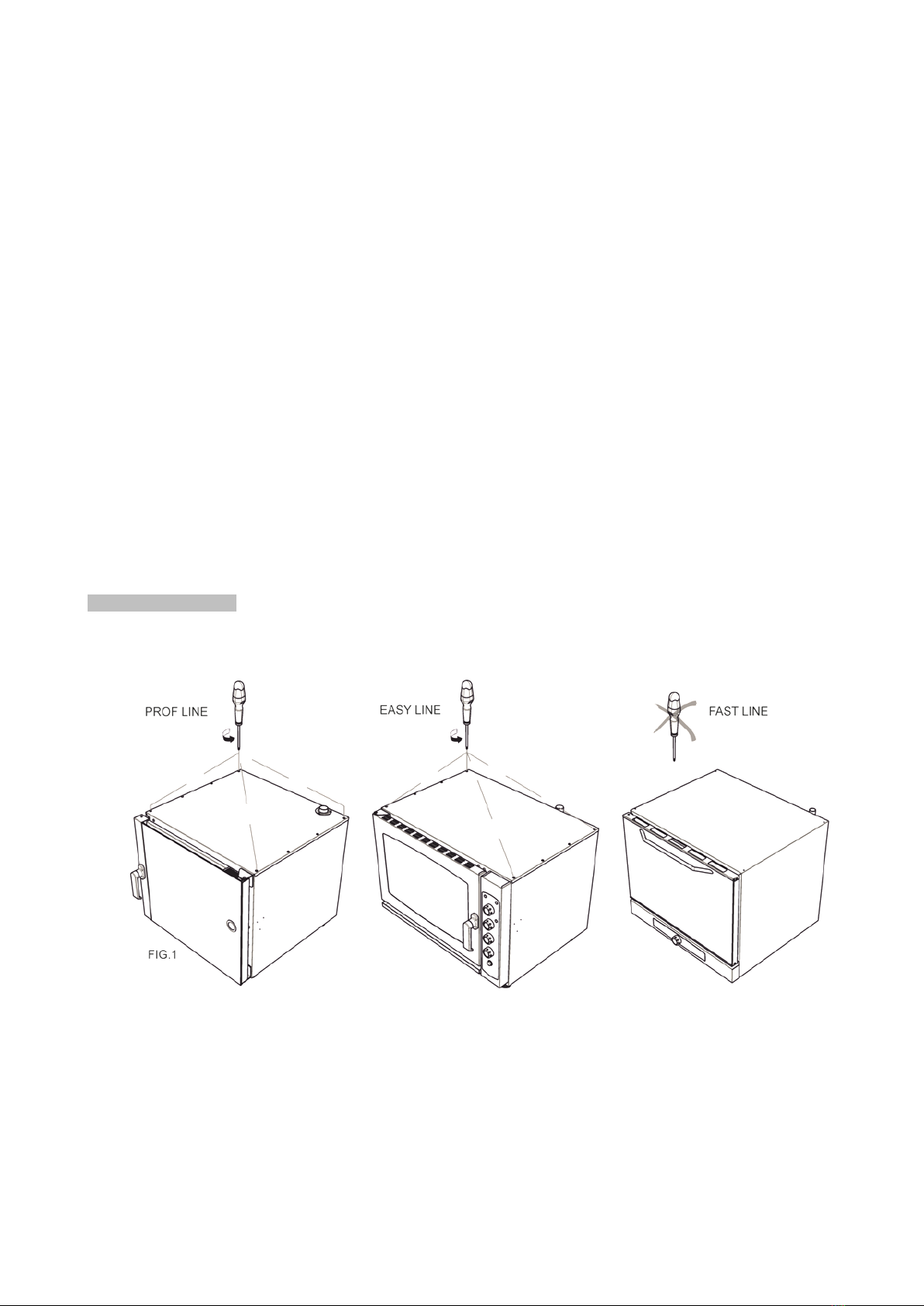
Forni modello PROF ed EASY: Rimuovere le quattro viti periferiche (Fig. 1)

6
2.1.1 - Togliere l'imballo all'apparecchiatura.
- svitare e rimuovere le viti del pannello di copertura
- rimuovere il pannello di copertura
2.1.2 - Posizionare la cappa sopra al forno facendo coincidere i fori presenti sul cielo del forno con i
fori presenti sui fianchi della cappa.
Fissare la cappa al forno come segue:
Modelli forni PROF ed EASY- fissare la cappa alla parte superiore del forno usando le 4 viti rimosse
nel paragrafo 2.1.
Modello forno FAST- usare le 4 viti in dotazione all'apparecchiatura.
ALLINEAMENTO FISSAGGIO
2.1.3 -(Fig.2A e 2B) Le fascette metalliche fornite in dotazione devono essere inserite alle estremità
libere del tubo metallico di Aspirazione (1) (posto sulla cappa) e del tubo Scarico Vapore (2)
(posto sul tetto del forno) Eseguire correttamente l'accoppiamento tra questi elementi servendosi
del tubo in silicone resistente ad alta temperatura.
Per una corretta connessione:
- inserire l'elemento flessibile per una profondità minima di 3 cm
-serrare bene la fascetta metallica accertandosi della tenuta dell'intero sistema.

7
2.1.4 - Riposizionare e fissare con le viti il pannello di copertura superiore.
8
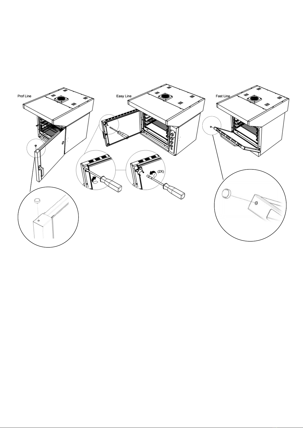
2.1.5 - Sensore magnetico
Modelli forni PROF e FAST- avvitare il sensore magnetico nell'apposito inserto esagonale posto nella
porta (Figura 3, dettagli, 3A e 3C)
Modelli forni EASY- Svitare e rimuovere le due viti a testa esagonale poste sul montante della porta,
posizionare la staffa supporto magnete, in dotazione e, su quest'ultima avvitare il sensore (Figura 3,
dettagli, 3B).
2.2 –Allacciamento elettrico
L’allacciamento deve essere eseguito secondo le normative europee vigenti. Il collegamento
elettrico è di tipo monofase 220 –230 V ~ 50/60 Hz. La cappa a condensazione viene fornita con
cavo elettrico dotato di spina.
Attenzione!!! –E’ obbligatorio porre un interruttore di sicurezza bipolare a monte della cappa.
Attenzione!!! –E’ obbligatorio eseguire un corretto collegamento a terra secondo le norme di
sicurezza dell’impianto elettrico.
2.3 - Allacciamento idrico
Provvedere ad interporre tra la rete idrica e l’apparecchiatura, un rubinetto di intercettazione.
Collegare l'ingresso acqua (1 Fig. 4) della cappa alla rete idrica mediante il tubo in gomma in
dotazione (4 Fig.4).
La cappa a condensazione è progettata per ottimizzare i consumi alla pressione di 2 Bar.
2.4 –Collegamento allo scarico
L’acqua in uscita dalla cappa può raggiungere temperature fino a 90 °C. I condotti da utilizzare
per lo scarico dell’acqua (3 Fig.4) devono pertanto essere in grado di lavorare a tali temperature.
3A
3C
Fig. 3
3C
3B

9
2.5 - Montaggio ed installazione dei filtri
Prelevare il filtro e i distanziali di compensazione (dove previsti) dalla confezione di fornitura
dell'accessorio ed inserirli nelle opportune guide di posizionamento poste sulla parte inclinata
anteriore: posizionare dapprima i distanziali di compensazione (dove previsti) sulla superficie di
appoggio della cappa accertandosi che siano inseriti sulle alette guida, appoggiare
successivamente, il filtro sulla guida superiore quindi completare l'assiemaggio inclinando il filtro
fino al suo corretto inserimento sull'aletta inferiore della cappa.
2.6 –Accensione
Completata l’istallazione fornire l’alimentazione elettrica ed idrica alla cappa a condensazione.
Essa entrerà in funzione autonomamente al raggiungimento della temperatura, rilevata dalla
sonda, di 60° C. La fase di arresto aspirazione fumi avviene al raggiungimento della temperatura di
40°C.
La seconda velocità del motore di aspirazione è gestita dal sensore magnetico anteriore ed entra
in funzione automaticamente all'apertura della porta del forno.

10
3. MANUTENZIONE
Attenzione!!! –Prima di eseguire qualsiasi tipo di manutenzione, assicurarsi di togliere la tensione
all’apparecchiatura.
Attenzione!!! –Qualsiasi operazione di manutenzione deve essere effettuata solamente da
personale qualificato. Le opere di manutenzione possono prevedere la rimozione del pannello di
copertura superiore. La rimozione del pannello deve essere eseguita rimuovendo le viti perimetrali
(Vedere sequenza 2.1.1-Pag.5) e prestando attenzione, durante il sollevamento, a non
danneggiare il cablaggio elettrico.
3.1 –Smontaggio dei filtri d’aria: La rimozione dei filtri avviene mediante lo scorrimento verso l’alto
da compiere in maniera tale di liberare dapprima, il componente dalle sede di appoggio inferiore.
Il riassemblaggio del componente viene eseguito invertendo le fasi precedentemente descritte.
3.2 –Pulizia dell’ugello: Si ha accesso all’ugello di condensazione rimuovendo il coperchio della
camera di condensazione (Fig.5) La pulizia deve essere eseguita con prodotti idonei alla rimozione
del calcare. La pulizia dell’ugello va eseguita con cadenza annuale od ogni qualvolta si dovessero
ravvisare dei malfunzionamenti.
3.3 –Sostituzione dell’elettrovalvola.
La sostituzione dell'elettrovalvola avviene mediante la rimozione delle sue viti di fissaggio (Fig.5)
previa rimozione del tubo di collegamento (componente 4 di Fig.4 -Pag.7) atto al circolo d’acqua.
3.4 –Sostituzione della scheda elettronica
La sostituzione della scheda elettronica deve essere eseguita rispettando, in ordine, la procedura:
A. Scollegare la cappa dall’alimentazione elettrica e serrare il rubinetto di alimentazione
acqua.
B. Rimuovere il pannello di copertura superiore (Vedere sequenza 2.1.1-Pag.5)
C. Scollegare la scheda elettronica da sostituire.
D. Sostituire la scheda
E. Riassemblare –Eseguire in maniera invertita le operazione precedentemente descritte

11
3.5 Ricambi
Possono essere utilizzati solo componenti di ricambio originali o componenti dei quali viene
rilasciata autorizzazione da parte della casa produttrice dell'apparecchio. Non riparare o sostituire
alcun componente dell'accessorio che non sia stato raccomandato da questo manuale. Tutti gli
interventi devono essere effettuati da personale tecnico autorizzato. Per chiedere un componente
di ricambio si deve indicare il modello della cappa riportato sull’targhetta dell’apparecchiatura.
I ricambi che possono essere forniti sono:
a.-Scheda elettronica cod.4621830
b.-Elettrovalvola cod.4690060
c.-Ugello cod. 4261870*, 4261880** (1,5 Lt/min*) (3,0 Lt/min**)
d.- Sonda di temperatura cod. 4630210
e.- Motore aspirazione cod. 4652130*(750 m3/h*) (1000 m3/h**)
f.- Sensore magnetico cod. 4611010
g.- Magnete porta cod. 3280020
*Vedere la portata dell’apparecchio in tabella “DATI TECNICI CAPPE CONDENSAZIONE”.
4. PULIZIA
Attenzione!!! –Non utilizzare detergenti contenti: sabbia, soda caustica, acidi o cloruri che
intaccano la superficie.
Attenzione!!! –Qualsiasi intervento di pulizia deve essere eseguito con la cappa scollegata dalla
rete elettrica. La cappa va pulita utilizzando un panno umido con detersivo non abrasivo e
asciugando le superfici utilizzando un panno asciutto.

12
ENGLISH
INDEX
Data technical sheet 13
Warning 14
Installation 14
Positioning
Electrical connection
Water connection
Drain connection
Mounting and installation of filters
Turning
Maintenance. 18
Removing the filters air
Cleaning the
Replacing solenoid
Replacing the electronic board
Spare parts
Cleaning 19
Wiring diagram 38
Certification 39

13
TECHNICAL DATA
Dimensioni Esterne Peso
HOOD
Model
OVEN
Model
CAPACITY
Power
V / Ph / Hz
kW max
A
max
EXTERNAL
DIMENSIONS
GROSS
WEIGHT
Acqua
L/min
Aria
M3/h
W
D
H
CFE-11C
PDE-104
PDE-106
PDE-110
1,5
750
0,27
230 / 1 / 50
0,3
1,35
752
1060
274
40
CFE-14C
PDE-115
PDE-120
PDE-613
PDE-616
3
1000
0,27
230 / 1 / 50
0,3
1,35
862
1160
274
50
CFE-21C
PDE-207
PDE-210
3
1000
0,27
230 / 1 / 50
0,3
1,35
862
1450
274
65
CFE-24C
PDE-220
3
1000
0,27
230 / 1 / 50
0,3
1,35
65
CFE-46C
PDE-404
PDE-406
PDE-410
1,5
750
0,27
230 / 1 / 50
0,3
1,35
862
1160
274
45
CFE-66C
PDE-605
PDE-607
PDE-610
1,5
750
0,27
230 / 1 / 50
0,3
1,35
45
CFE-8C
EDE-805
1,5
750
0,27
230 / 1 / 50
0,3
1,35
762
1010
274
35
CFE-9C
EDE-905
EDE-907
EDE-910
1,5
750
0,27
230 / 1 / 50
0,3
1,35
922
1010
274
45
CFFE-14C
FDE-903
FDE-905
FUE-904
FUE-906
1,5
750
0,27
230 / 1 / 50
0,3
1,35
782
1010
274
30
CFFE-35C
FDE-803
FDE-805
1,5
750
0,27
230 / 1 / 50
0,3
1,35
622
1010
274
30
14
1. WARNING
This user’s manual is an integral part of the appliance and must be kept and made available to operators for
future reference throughout the entire service life of the product. Before performing any operation, read
carefully the manual information relating to safety, installation, use, and maintenance.
The appliance shall be used only for its intended use and by duly trained and qualified personnel. The
installation, maintenance, and repairs must be exclusively performed by an authorized technical assistance
centre or by qualified professionals, in compliance with the applicable standards and the instructions of the
manufacturer. Before using the appliance for the first time, make sure that the connection tubes between the
oven and the condensation chamber have been properly sealed with silicone capable of withholding up to
300 °C. Every time that the hood or the oven over which the hood is installed are moved, it is advisable to
check that the connection between the tubes and the oven remain sealed.
It is compulsory to ground the appliance in compliance with the safety standards of the electric system.
The plug used to connect to the power cord must be compliant with the applicable standards.
Do not block the openings, the venting and heat-dissipating grooves.
Use the hood with an ambient temperature ranging between +5 °C and +35 °C.
This appliance has been designed for professional use and is compliant with the applicable EC directives. The
function of the appliance consists in condensing the steam given off by the oven; any other use shall thus be
deemed inappropriate.
The manufacturing company deny liability both for direct and indirect damages caused by an inadequate
installation, tampering, poor maintenance, and improper use and whenever the standards referred to in the
user’s manual are not met with.
2. INSTALLATION
All the materials –except silicone–used in the installation must be capable of withholding a temperature of 150
°C without suffering deformation and/or surface defects.
2.1 - Positioning
PROF LINE- EASY LINE:Remove the 4 screws as in picture.

15
2.1.1 - Remove the emballage from the hood.
- Unscrew and remove the screws of the cover panel, on the top of the hood.
- Remove the cover panel, on the top of the hood.
2.1.2 - Place the hood over the oven, lining up the holes in the roof with holes on the sides of the hood.
Fix the hood to the external structure of the oven as follows:
PROF LINE- EASY LINE::Fix the hood to the external structure of the oven using the 4 screws removed in step
2.1 - Positioning
- FAST LINE: Use the 4 screws supplied with the appliance
2.1.3 - The metal clamps supplied, must be inserted to the free ends of the two Sucking metal tubes (1) of the
hood, to connect them with the two Steam vents (2) on the oven's top.
Correctly position these elements using the silicon tube (resistant to high temperatures).
For a successful connection:
- Insert the flexible element to a minimum depth of 3 cm.
- Tighten well the metal clamp
SURE SEAL WHOLE SYSTEM.

16
2.1.4 - Replace the top cover and secure it with screws own.
2.1.5 - MAGNETIC SENSOR
PROF LINE- FAST LINE:fix magnetic sensor on the oven door on the insert hex place on door
EASY LINE:
-Unscrew and remove the two hex-head screws, located on the door pillar
-Place the magnet bracket (supplied), coinciding holes, on the door column and, secure it with the screws
removed previously.

17
2.2 –Electric wiring
The connection shall be made in compliance with the applicable European regulations. Electric
wiring is single-phased 220 –230 V ~ 50/60 Hz. .). The condensation hood is supplied with an electric
cable with a plug. Warning!!! –It is compulsory to fit a two-way safety switch on the hood.
Warning!!! –It is compulsory to ground the installation properly in compliance with the safety
standards of the electric system.
2.3 - Connection to the water system
The connection to the water system must be performed by qualified personnel who shall fit a shut-
off between the water system and the appliance. Connect the water inlet (1 Fig. 4) of the hood to
the water supply by means of the rubber hose supplied (4 Figure 4). The condensing hood has
been designed to optimize consumption when the network pressure reaches 2 bar. To this end, it is
recommended to fit a pressure gauge and a pressure regulating system upstream of the hood
connection.
2.4 –Drain connection
The water leaving the hood may reach high temperatures of about 80-90 °C. The pipes used to
evacuate water shall be able to withstand such temperatures. The position of the drain is shown in
the picture (3).
2.5 - Mounting and installation of filters
Remove the filter and spacers compensation (where applicable) from the package delivery
accessory and place them in the appropriate positioning guides placed on the sloping front: first
place spacers compensation (where applicable) on the surface of the hood and make sure they
placed on the fins guide, then place the filter on the top rail and then complete the assembly by
tilting the filter until it is correctly inserted at its lower hood.
2.6 –Turning on the appliance
1- water inlet
2- electrical supply
3- water drain
4- connection tube to the water system

18
Completed the installation supply electrical power and water to the condensation hood.
It will operate independently on reaching temperature, detected by the probe, of 60 ° C. The step
of stopping fume extraction takes place on reaching the temperature of 40 ° C.
The second speed of the suction motor is operated by the magnetic sensor front and comes into
function automatically when the door of the oven.
3. MAINTENANCE
Warning!!! –Before performing maintenance operations, cut off power with the appropriate switch
or pull out the plug.
Warning!!! –Any maintenance operation shall be performed by qualified personnel only. The
maintenance interventions may require removing the front or the rear cover. To remove the front
cover, unscrew the perimeter screws (see 2.1.1) paying attention not to damage the electric
wiring when lifting the cover.
You may also remove the rear cover unscrewing the perimeter screws and lifting completely the
cover, paying attention not to disconnect the electric wiring.
Warning!!! –When removing the panels, handle the cover with care and wear gloves to protect
your hands from possible cuts.
3.1 –Removing the air blade filters. To disassemble the filters, seize them and scroll them up so that
they get unthreaded from the lower runner. The filter will be fully removed if you rotate slightly the
lower wall. Perform the opposite operation to re-assemble the filter.
3.2 - Cleaning Nozzle: You have access to the nozzle of condensation by removing the cover of
the condensation chamber (Figure 5) Cleaning should be done with products suitable for the
removal of limestone. The nozzle cleaning is performed annually or whenever you were to
recognize malfunctions.
3.3 - Replacing the solenoid valve.
The replacement of the solenoid is by removing its fastening screws (Figure 5) after removing the
connecting tube (part 4 of Figure 4 -Pag.7) act the circle of water.
3.4 - Replacing the electronic board
The replacement of the electronic board must be carried out following, in order, the steps:
A. Disconnect the hood from the power supply and tighten the supply tap water.
B. Remove the top cover (See 2.1.1 )
C. Disconnect the electronic board to be replaced.
D. Replace the card
E. Reassemble - Perform in a reversed the operation previously described
NOZZLE
ELECTROVALVE

19
3.5 SPARE PARTS
They can be used only genuine replacement parts or components of such authorization is issued by the
manufacturer of the device. Do not repair or replace any part of the accessory that was not recommended
by this manual. All work must be performed by authorized specialists. To request a replacement part, you
specify the hood model reported sull'targhetta equipment.
The spare parts that can be provided are:
a - Electronic card cod.4621830
b -Electrovalve cod.4690060
c - Nozzle cod. 4261870*, 4261880** (1,5 Lt/min*) (3,0 Lt/min**)
d - Temperature Probe cod. 4630210
e - Sucktion Motor cod. 4652130*(750 m3/h*) (1000 m3/h**)
f - Magnetic probe cod. 4611010
g - Magnetic door switch cod. 3280020
* See the capacity of the hood in the "TECHNICAL DATA CONDENSATION HOODS".
4. CLEANING
Warning!!! –Never use detergents containing sand or caustic soda, acids or chlorides that may corrode the
surface.
Warning!!! –Cleaning must be performed with the hood de-energized. To clean the hood, use a wet cloth with
non-abrasive detergent and dry the surfaces using a dry cloth.
MAGNETIC SENSOR
TEMPERATURE PROBE
ELECTRONIC
CARD

20
DEUTSCH
Inhalt
Technische Daten 21
Hinweise 22
Installation 22
Aufstellung
Elektrischer Anschluss
Wasseranschluss
Anschluss an den Abfluss
Montage und Installation der Filter
Einschaltung
Wartung 8
Entfernung der Luftfilter 8
Reinigung der Düsen 8
Ersetzung des Solenoidventils 8
Ersetzung der Elektronikkarte 8
Ersatzteile 9
Reinigung 9
Schaltplan 10
Zertifizierung 11
This manual suits for next models
9
Table of contents
Languages:
Popular Ventilation Hood manuals by other brands


Brandt
Brandt LIB0089534B Instruction on mounting and use

Electrolux
Electrolux RH30WC55GS Guide d’installation, utilisation et d’entretien

Siemens
Siemens LC91KWW62S User manual and installation instructions

Halton
Halton KVF Capture Jet Operation

Dacor
Dacor HRV46 installation instructions

Remus
Remus 54483 362018 Installation instruction


