Step 1 Look for this icon. It means a
video assembly tip is available at
www.sauder.com/services/tips
419200www.sauder.com/services Page 5
(12 used)
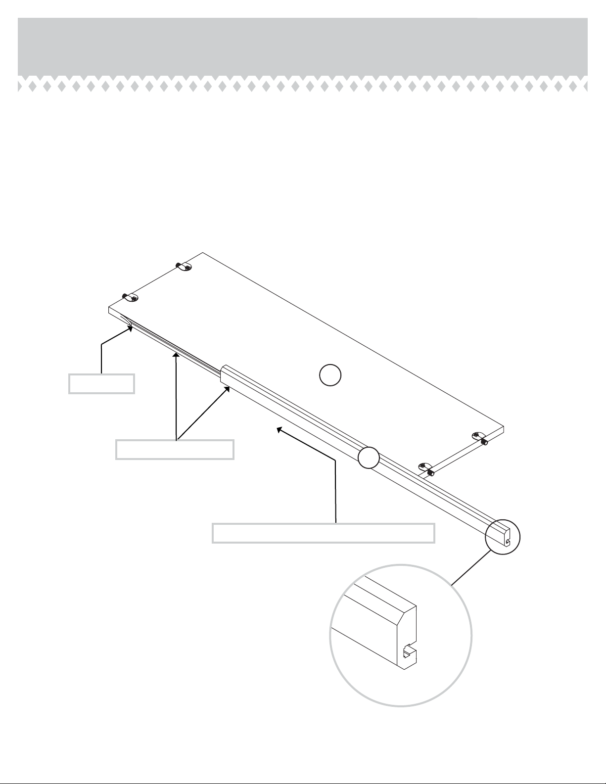
10F
Do not tighten the TWIST-LOCK® FASTENERS in this step.
å Assemble your unit on a carpeted floor or on the empty
carton to avoid scratching your unit or the floor.
å To begin assembly, push a SAUDER TWIST-LOCK®
FASTENER (10F) into the large holes in a TOP/BOTTOM (C)
and SHELF (D).
å Repeat this step for the other TOP/BOTTOM (C).
10F
D
C