51.025/2 ASM 124
Operation
By connecting the power supply to either cable 2a or cable 2b, the final control element can be moved
into any desired position.
Direction of rotation for 3-point control (as viewed from the actuator towards the spindle
adaptor)
– the spindle adaptor rotates in a clockwise direction if power is connected to the brown wire (2a)
– the spindle adaptor rotates in an anti-clockwise direction if connected to the black wire (2b).
Direction of rotation for 2-point control, 24V
(as viewed from the drive towards the spindle adaptor):
the black wire (2b) is always live:
– the spindle adaptor rotates clockwise, with voltage on the brown wire (2a).
– the spindle adaptor rotates counter-clockwise, with no voltage on the brown wire (2a).
Direction of rotation for 2-point control, 230V
(as viewed from the drive towards the spindle adaptor):
The brown wire (2a) is always live:
– the spindle adaptor rotates counter-clockwise, with voltage on the black wire (2b).
– the spindle adaptor rotates clockwise, with no voltage on the black wire (2b).
In the end positions, the electronic end position detector responds (motor switch-off). In case of an over-
load, a magnetic clutch protects the gearbox. The effective end position is determined by the damper
stop guide or by a rotation-angle limiter, or when the maximum rotation angle of 95° is reached.
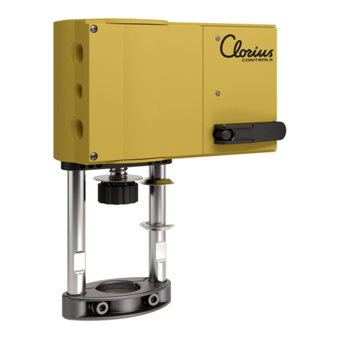
Manual adjustment by turning the spindle adaptor after decoupling the gears (button on housing cover).
For 3-point control, the direction of rotation can be changed by swapping the connections over.
Engineering and fitting notes
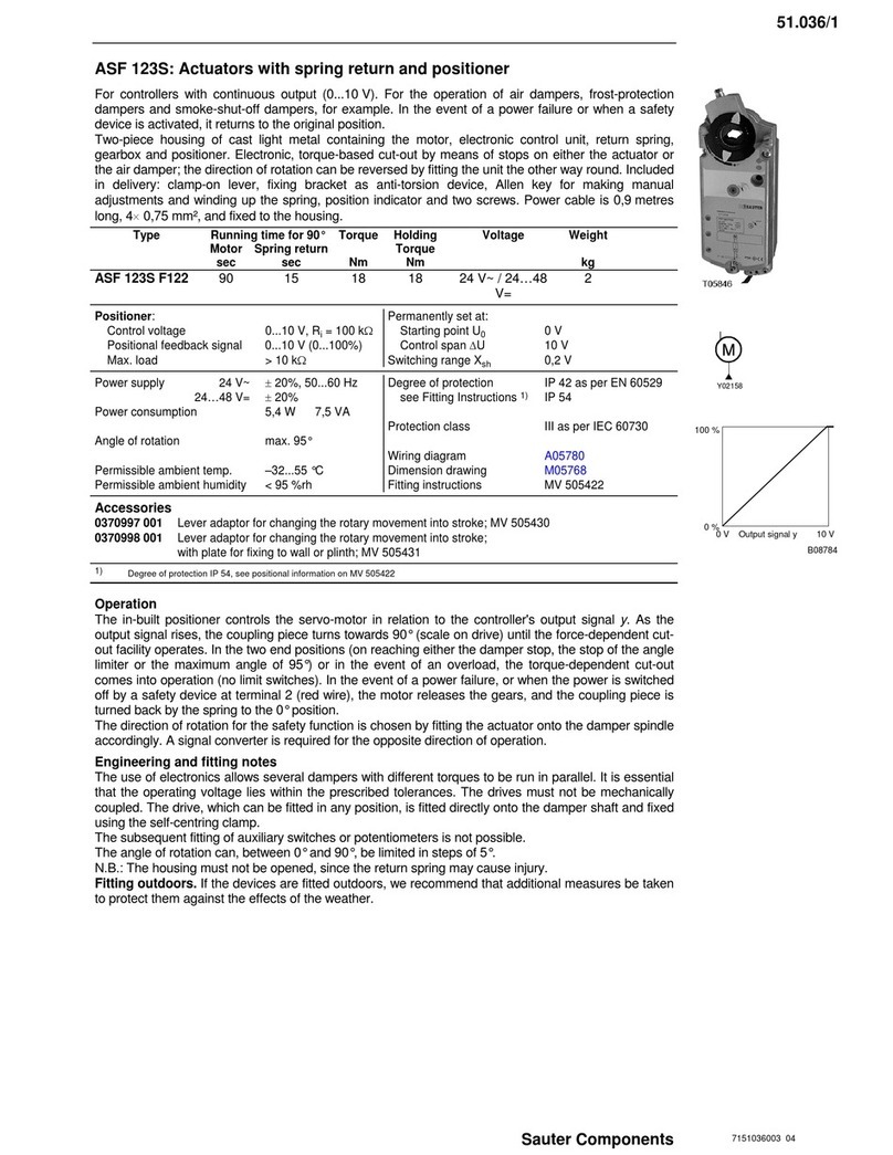
The concept for the synchronous motor and the electronics guarantees that several air dampers can
be run in parallel with different torque levels. The drive can be mounted in any position, can be inserted
directly onto the damper shaft and is fixed using the self-centering clamp.
Caution! The housing must not be opened.
The following accessories can be fitted to each actuator: one set of single auxiliary contacts or one set
of double auxiliary contacts or one potentiometer. By re-positioning a disc under the coupling piece, the
angle of rotation can be limited between 0 and 90° in steps of 5°. The coupling piece is suitable for
damper spindles of Ø 10...20 mm and 10...16 mm.
Installation in the open air. We recommend that the equipment is given additional protection against
weather influences if installed outside of the building.
Additional technical data
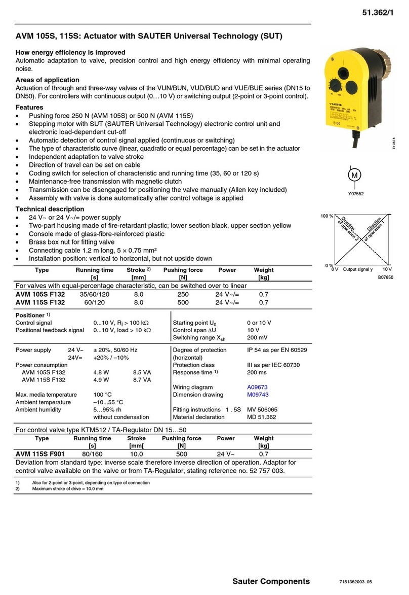
The upper section of the housing, with the lid, manual adjustment knob and the cap button, contains
the synchronous motor with the capacitor and the electronic control and switch-off units. The lower
section of the housing contains the maintenance-free gears, the magnetic clutch and the spindle adap-
tor. To reverse the direction of rotation with 3-point control, the brown and the black wires must be
transposed.
Auxiliary change-over contacts
Switch rating: max. 230V a.c.; min. current 20 mA at 20V
Switch rating: max. 4...30V d.c.; min. current 1...100 mA
Power consumption:
Type Running time
s
Condition active power P
W
apparent power S
VA
ASM 124 F120 120 Operating 2,9 5,6
Standstill 0,5 5,1
ASM 124 F122 120 Operating 2,3 2,,4
Standstill 0,03 0,4
CE conformity
EMC directive 2004/108/EC Machine directive 2006/42/EC (II B) Low-voltage directive 2006/95/EC
EN 61000-6-1 EN 1050 EN 60730-1
EN 61000-6-2 EN 60730-2-14
EN 61000-6-3 Over-voltage category III
EN 61000-6-4 Degree of pollution II
Sauter Components 7151025003 04
