51.377/2
AVM 234S
Sauter Components
Operation
Depending on the type of connection (see the wiring diagram), the actuator maybe used as a continuous
(0...10 V and/or 4...20 mA), 2-point (OPEN/CLOSED) or 3-point (OPEN/STOP/CLOSED) device with an
intermediate position.
The actuator's running time can be set according to the specific requirements, using switches S1 and S2.
Switches S3 and S4 are used to set the characteristic (equal percentage, linear or quadratic).
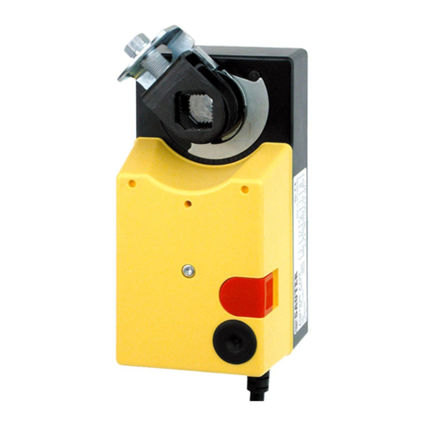
The external lever allows you to adjust the position manually. When the leveris folded out, the motor cuts
out. When the lever is folded back into place, the setpoint position is adopted again (without initialisation).
If the lever is folded out again, the actuator stays in this position.
Initialisation and feedback signal
When used as a continuous actuator, the device initialises itself automatically. As soon as power is ap-
plied to the actuator for the first time, it moves to the valve's lower limit, thus enabling automatic connec-
tion with the valve spindle. Then it moves to the upper limit and the value is recorded and saved by a
travel measurement system. The control signal and the feedback signal are adjusted to this actual stroke.
There is no re-initialisation in the event of a power failure. The values are saved.
To re-initialise, the actuator must be connected to the power supply and there must be a continuous input
signal at 3u or 3i. To trigger an initialisation, fold the lever out and back in again twice within 4 s. Both of
the LEDs will then flash red.
During initialisation, the feedback signal is inactive, or it corresponds to a value of 0. Initialisation uses the
shortest running time. The re-initialisation is not valid until the entire procedure has been completed.
Folding the lever out again will interrupt the procedure.
If the valve actuator detects a blockage, it will report this by setting the feedback signal to 0 V after ap-
prox. 90s. However, the actuator will try to overcome the blockage during this time. If the blockage can
be rectified, the normal control function is activated again and the feedback signal is restored.
No initialisation is performed with 2-point or 3-point control. The feedback signal is inactive.
Accessories
0313529 001*
Split-range unit toset sequences, MV 505671; A09421
Module, plug-in type, for 2-/3-point and continuous activation, additional power 2 VA
0372332 001*
230 V ±15% power supply, MV 505901
0372332 002*
100 V to 110 V ±10% power supply, MV 505901
Auxiliary change-over contacts (2 pcs. each) 12...250 V∼
0372333 001*
Infinitely variable, min. 100 mA and 12 V, additional load 6(2) A, MV 505866
0372333 002*
Gold-plated contacts, from 1 mA and up to 30 V; further range 3(1) A; MV 505866
0372334 001*
Potentiometer 2000 Ω, 1 W, 24 V; installation as per MV 505894
0372334 002*
Potentiometer 130 Ω
1)
, 1 W, 24 V; installation as per MV 505894
0372334 006*
Potentiometer 1000 Ω, 1 W, 24 V; installation as per MV 505894
0372336 180*
Adaptor
2)
(required for medium between 130 °C and 180 °C, MV 505902)
0372336 240*
Adaptor
2)
(required for medium between 180 °C and 240 °C, M V 505902)
Fitting kit for AVM234S F132 on Sauter valves (for 0372338 002, no adaptor required)
0372338 001 V/B6 up to DN 50 and V/BXD, V/BXE up to DN 50 with stroke 14 mm. MV 505903
0372338 002 V/B6 of DN 65…150 and V/BXD, V/BXE from DN 65 with stroke 40 mm. MV 505903
0372338 003 Conversion kit for AVM 234S F132-5 on standard actuator AVM 234S F132, MV 505903
0372338 004 Conversion kit for AVM 234S F132-6 on standard actuator AVM 234S F132, MV 505903
Set of adaptors for non-Sauter valves
0372376 010 Siemens with 20 mm stroke or spindle ø10 mm, MV 505974
0372376 014 Siemens with 40 mm stroke or spindle ø14 mm, MV 505974
0372377 001 JCI DN15…150 with 14, 25 or 40 mm stroke or spindle ø10, 12 or 14 mm, MV 505975
0372378 001 Honeywell with 20 mm stroke, MV 506069
0372378 002 Honeywell with 38 mm stroke, MV 506069
0372386 001 LDM Typ RY113 R/M, MV P100000538
0372387 001 Fitting kit SAUTER-Satchwell VZF1727
0372389 001 ITT-Dräger, DN 15…32, MV P100000376
0372389 002 ITT-Dräger, DN 40…50, MV P100000376
0378263 001 End stop guide (required forV/BXD, V/BXE DN15…50, V/B6 DN15 with kvs ≤1 m
/h)
0386263 001 Screwed cable fitting, M16×1,5
0386263 002 Screwed cable fitting, M20×1,5
*) Dimension drawing or wiring diagram is available under the same number
1) This potentiometer may only be used as a voltage divider.
2) Adaptor not required for the F132-6 version
7151377003 10
