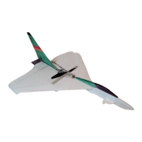
Sawn Craft Cherokee 24 User guide

Cherokee 24
Assembly and Setup Manual
Specifications Recommended Power System
Wingspan 24” ESC 10A Brushless
Overall Length 18.3” Motor 40 to 50 watt out runner (14g)
Wing Area 133.9 in2Servo 4x 3.6g Sub-Micro
Flying Weight 3.9oz / 111g RX 6-Channel (4-ch minimum)
Intended Use Indoor/Outdoor Battery 180 to 300mAh 2S 7.4V 25C LiPo (or similar)
Revised 2016-10-19

ThankyoufromSawnCraft.
ThankyouforpurchasingtheSawnCraftCherokee24aircraftkit,thefourthmodelinourFrontYard
Fightersseries!ThismodelisaslightdeparturefromthewarbirdsthatmakeuptherestoftheFYFline,
butthebuildandperformanceareverymuchthesameastherestoftheseries.Likethefull‐scale
Cherokee,inyourhandsisaremarkablyversatileairplanedesignedtodeliverapleasurecruiserwithan
incrediblelookintheair.ThelightweightandresilientEPPandcarbonconstructionmakesitpossiblefor
youtoexperienceawideperformanceenvelope.Thismeansthatnomatterhowyouliketofly,you’ll
enjoybothstabilityandmaneuverabilitywithoutanysacrificeinprecisionorcontrolfeel.
YourSawnCraftCherokee24aircraftkitrepresentsthebenchmarkofindoorflightperformanceand
aerobaticversatility.Allyouhavetodonextisreadandapplytheinformationpresentedinthis
instructionmanual.
Isincerelyhopethatyouenjoyyourmodelasmuchaswedo!Ifyouhaveanytroubleswiththese
instructionsorinthesetupofyourmodelfeelfreetocontactusandwewillprovideyouwiththe
serviceyouexpectfromahobbyist‐ownedandoperatedbusiness.
JonathanSawn
Owner,SawnCraft
Jonathan@Sawn‐Craft.com

Table of Contents
1Introduction1
1.1StyleConventions1
1.2RequiredTools&Supplies1
1.3RequiredPartsforCompletion 2
1.4IncludedPartsDescription 3
2AssemblyInstructions4
2.1PartsSheetRemoval4
2.2CuttingControlSurfaceBevels5
2.3HorizontalComponentAssembly6
2.4VerticalComponentAssembly8
2.5LandingGearAssembly9
2.6ServoEZConnectorAssembly&Installation12
2.7WingServoInstallation13
2.8UpperVerticalFuselageInstallation14
2.9ElectronicsInstallation15
2.10GussetInstallation18
2.11Painting/Decorating19
3SetupandTuning20
3.1CenterofGravity20
3.2RadioSetupandMixing20
3.3ControlThrowsandExpo21
3.4Launching/Take‐Off21
3.5FlyingTips21
3.6Repairs&SpareParts22

SawnCraftCherokee24Manual 10/17/16
1 Introduction
Thecontentsofthismanualassumetheoperatorwillhavethefollowingprerequisites:
•Understandingofallappropriatesafetyproceduresandrequirements
•Theabilitytofollowwrittenproceduresandpossessbasichobbybuildingskills
1.1 Style Conventions
Belowaretheimportantstyleconventionsthatwillbeusedthroughouttheguide.
Note:Keypointsorhintsforsuccesswillbeformattedinthismanner.
Warning:Anyareathatposeseitheraphysicalhazardorthedangerwillbeformattedinthismanner.
Arrowsinformwheretoclickortoperformthespecifiedoperation.
1Circleditemsinformofitemsofinterestforthespecifiedoperation.Circleditemswilltypicallybe
accompaniedbytextfurtheridentifyingtheregionofinterest.
1.2 Required Tools & Supplies
Thelistbelowcontainsalloftherequiredtoolsandsuppliesthatarerequiredfortheassemblyand
tuningofthismodel.
•Clean,flatworksurface(buildingboard)
•#11hobbyknifeorotherrazorknife
withspareblades
•2xMetalstraight‐edgeruler
•T‐Pins(1”–1.5”areideal)
•Scissors
•PermanentMarker
•Drillw/1/16”&5/64”bit
•BeaconFoam‐Tacfoam‐safeadhesive
•CAadhesive
•3MBlendermTape
•Maskingtape
•Waxpaper
•Solderingiron&solder
•Heatgun
•Wirecutters
•Needlenosepliers
SawnCraftrecommendstheuseofBeaconFoam‐Tacadhesiveand3MBlendermHingeTapefor
theconstructionofthismodelduetoitsstrength,lightweight,andeasyuse.BothBlenderm
andFoam‐TaccanbepurchasedbyvisitingtheBuildingSuppliestabonSawn‐Craft.com

SawnCraftCherokee24Manual 10/17/16
1.3 Required Parts for Completion
Thelistbelowcontainsthetestedandrecommendedpartsforyourmodel:
•SawnCraftFYFCompletionKit
oTurnigyC18222100kvmotor
o10ABrushlessESC
o4x3.6gServos
o6‐ChannelReceiver(Optional)
o6”x3”ElectricProp
oJSTFemalePigtail
oShrinktube,etc.
•180mAhto300mAh2S25CLiPoBattery
•Velcro
Pleasenotethatotherpowersystemsandcomponentsmaybecompatibleandmaywork
withoutissue,butthelistedcomponentshavebeenusedsuccessfullybySawnCraft.
Optional Parts for Completion
Tomakeyourbuildeasierandensurethenicestlookingfinishedproduct,thefollowingproductsare
offeredonSawnCraft.com.SeetheBuildingSuppliestabfortheseproducts.
2
Theorderofassemblypresentedinthisinstructionhasbeentestedanditisrecommendedthat
youdonotdifferfromthemtoprovidethemostaccurateandeasiestassemblypossible.Also,
theconstructiontechniquesofmanyofouraircraftareextremelysimilar.Thoughwewilltryto
includeasmanyphotosofyourspecifickitinthisinstruction,otherkitassemblyphotosmaybe
usediftheinstructionand“look”oftheassemblyisthesame.
If you would like to view larger images or print out your own version
of this manual it is available 24/7 on Sawn Craft's website. Visit the
Support tab, or use this link to get there:
http://sawn-craft.com/p/support

SawnCraftCherokee24Manual 10/17/16
1.4 Included Parts Description
Pleaseinspectyourkitandensurethatalllistedpartsarepresentandundamaged.Ifyoufindmissing
partsorsignsofdamagepleasecontactSupport@Sawn‐Craft.comforassistance.
a) 22.75”CarbonStrip(NotPictured)
b) 3mm&6mmEPPMotorSpacers
c) Rudder
d) Elevator
e) Wing(2each)
f) Aileron(2each)
g) 3mmEPPGussets(2eachlong,2eachshort)
h) LowerVerticalFuselage
i) HorizontalFuselage
j) UpperVerticalFuselage
k) SmallPartsBag:(Picturedatright)
k.1 25mmWheel(3each)k.6 PlywoodMotorMount
k.2 8.5”CarbonStripk.7 PlywoodControlHorns(4each)
k.3 5”CarbonRod(2each)k.8 WireControlRods(4each)
k.4 5.5”CarbonRodk.9 MicroLinkageStoppers(4each)
k.10 24”LandingGearBindingThreadk.5 3.5”1/16”Wire
3
a
b
b
j
f
i
d
g
h
e
c

SawnCraftCherokee24Manual 10/17/16
2 Assembly Instructions
2.1 Parts Sheet Removal
•PartsRequired:
oKitPartsSheets
1) Usingasharphobbyknifecarefullycutthefoampartsoutofthesheets.Thesmalltabsholding
thepartsintothesheetcansometimesbetrickytofindsoifyouhavetroubleremovingapart
fromthesheetkeeplookingforthatlasttab.Onceoutofthesheet,youmaychoosetocleanup
theremainingtabonthefoampieceswithahobbyknifeandsomesandpaper.
2) Findandmarkwithmaskingtapethebottomofthehorizontalfuselage,bottomofthewinghalves,
bottomoftheailerons,andbottomoftheelevator.Thebottomofthesecomponentswillhavea
slotmilledforcarbonstrips.FindandmarkwithmaskingtapetheLEFTsideoftherudderandthe
LEFTsideofuppercomponentoftheverticalfuselage.Theselabelswillhelptoassurethebeveled
hingecutsareonthecorrectsideofthefoam.
4
Milledsparslot

SawnCraftCherokee24Manual 10/17/16
2.2 Cutting Control Surface Bevels
•PartsRequired:
oHorizontalFuselage
oAileron(2x)
oRudder
1) Bevelthehingedcontrolsurfaces,usingsteelrulersandfreshsingle‐edgerazorblades.Seta12‐
inchorlongermetalrulerbackingattheedgeofyourworkbench.Laythefoamparttobebeveled
ontheruler,aligningtheedgeoftheruledandtheedgeofthefoamnearesttoyou.Layasecond
steelrulerfacingdownfarenoughbacktoexposeenoughfoamtoallowa45degreeslicetobe
removed.Cutthefoamwiththesingle‐edgerazorbladeheldagainstbothrulers.Anglingtheblade
makesasmoothercut.
Bothaileronswillbebeveledontheirleadingedges,ensuringthattheyaremirrorimagesofeach
other.Therudderwillbebeveledonitsleadingedge,butthebevelshouldbecutoutoftheright
sideofthepart.Placetherudderwithitsleftsidedownonthetableandcutthebevelfromthe
rightside.Therearofthehorizontalfuselagewillbebeveledonthebottomsideofthepart.Place
thefuselagewithitstopsidedownonthetableandcutthebevelfromthebottomside.
EPPfoamdullsbladessurprisinglyfast,sobepreparedtochangetoafreshbladewhenyou
detectsnaggingorexcessdragasyoumakeyourcuts!
5

SawnCraftCherokee24Manual 10/17/16
2.3 Horizontal Component Assembly
•PartsRequired:
oWing(2each)
oAileron(2each)
oHorizontalFuselage
oElevator
o8.5”CarbonStrip
o22.75”CarbonStrip
1) Assembleandgluethehorizontalcomponents.Testfitallpartwithoutgluetocheckfitbefore
gluing.
Workoverwaxedpapertokeepfromgluingthemodeltothebuildingsurface.
‐Pinthehorizontalfuselagecomponenttothebuildingsurface.
‐Glueinthe8.5”carbonstripelevatorsparintotheelevator.
‐Gluethewinghalvesinplace.Wipeoffexcessglue.
‐Runabeadofgluealongthesparslotandpressthe22.75”carbonstripsparintoplace.Wipeoffany
gluethathassqueezedoutoftheslot.
Wipeoffallglueoutsideoffoamjoints.Thisgluedoesnotaddanystrength,butitdoesadd
weightwhichwillnegativelyaffecttheflightcharacteristicsofthemodel.
6

SawnCraftCherokee24Manual 10/17/16
2) Measuretheleadingedgeoftheelevatorandmakeasmallmarkatthemidpoint.Dothesamefor
thetrailingedgeofthehorizontalfuselage.
3) Makegluehinges.Pintothebuildingboardeachofthehingedparts,withbevelcutdownagainst
thebuildingboard.Locatethepartswiththematingsurfacesgentlytouching,ensuringthatthe
partsarecenteredorotherwisealignedcorrectly,dependingonthesurface.Runthesmallest
possiblebeadoffoamgluealongeachseam.Runafingeralongeachseamtopushtheglue
betweenthematingparts.Blotupexcessgluewithapapertowel.Letdryatsufficientlyforthe
gluetofullycure.Leavingthepartsovernightisidealforthestrongestandmosttruebond.
7
BUILDINGTIP:Ithelpstousesomeweighttoholdthepartsinalignmentwhiletheglueiscuring
ifyouchoosenottousepins.

SawnCraftCherokee24Manual 10/17/16
2.4 Vertical Component Assembly
•PartsRequired:
oMainAssembly
oTopVerticalFuselage
oRudder
oBottomVerticalFuselage
oPlywoodFirewall
oPlywoodControlHorns
o3mm&6mmMotorSpacers
1) Createagluehingebetweenthetopverticalfuselageandtherudder,justlikeyoudidwiththe
othercontrolsurfacesinthelaststep.Thereshouldbeabouta1/16”gapbetweenthetopofthe
verticalfuselageandthebottomoftherudder.Gluethecontrolhorntotheleftsideofthe
rudder.Setthisassemblyasidewhilethegluecures.
2) Flipthemainassemblysothatthebottomisfacingup.Runabeadofgluedownthecenterofthe
horizontalfuselageandattachthelowerverticalfuselage,ensuringthatallofthefrontofthe
pieceslineup.Applyglueintothecontrolhornslotsintheelevatorandaileronsandinsertthe
controlhornsallthewaysothatthebottomofthehorntouchesthetable.
8
3) Whiletheglueiscuringonthatpart,takeyourchosenmotorandmountittotheplywoodfirewall
usingthescrewsthatcamewithyourservos.Next,usingtheincluded3mmand6mmmotor
spacers,determinehowmanyandwhatcombinationofspacersyouwillneedtoensurethatthe
propclearsthefrontofthemodel.Youcanusetheverticaltopfuselageforthisdetermination.
IfyouareusingtheSawnCraftFYFCompletionkit,youwillonlyneedtouseoneofthe6mmmotor
spacers
Onceyouknowhowmanyspacersyouneed,removethemotorfromthefirewallandgluethe
necessaryspacerstotherearofthefirewall,ensuringthattheholesinbothpartslineup.Setthis
partasidetocureaswe’llneeditinafuturestep.

SawnCraftCherokee24Manual 10/17/16
2.5 Landing Gear Assembly
•PartsRequired:
oMainAssembly
o5”CarbonRod(2each)
o5.5”CarbonRod
o3.5”1/16”SteelRod
o25mmWheel(3each)
o24”Thread
oUnusedServoHorns
1) Installtwo5”carbonfiberrodsforlandinggear,aligningoneendoftherodwiththemilledcircle
onthebottomofthehorizontalfuselagewhilebothrodscrossthroughtheslotinthebottom
verticalfuselage.Useplentyofgluetosecuretherodendsbothontheendsandintheslot.
Installthe5.5”axletocompletethelandinggear.Slidethewheelsontheremainingcarbonfiber
rodandmakesuretheyspinfreely.Iftoosnugfit,chamferorslightlytapertheaxelrodendswith
sandpapertoallowthewheelsandhubstogoeasilyontotheaxle.
Tapeoneendoftheaxleinplaceandbindtheothersidewiththeblackthreadprovidedinthekit.
Removethetapeandbindtheotherside.Notethattheaxleshouldbearrangedbetweenthe
angledcomponentstobeasparalleltothesparaspossible,tothattheplanerollsasstraightas
possiblewhentaxiing.Adjusttheaxleforevenoverhangoneachsideandforparalleltothewing
sothattheplanesitslevel.SecurethethreadbindingwithadropifCAglueoneachside.Trimany
excesscarbonrodfromthediagonalifnecessary.
9
2) Slidethewheelsonandholdtheminplacewithaplastichubmadefromthecenterportionofa
servoarmfromamicroservo.Removethearmswithsidecutters,sandforsmoothness,drilloutto
5/64”ifnecessaryandslidethehubsontoholdthewheelsinplace.Allowalittleside‐to‐sideplay
foreasyrollingandsecurethehubswithadropoffoamglue.

SawnCraftCherokee24Manual 10/17/16
10
3) Bendthe3.5”1/16”steelrodaccordingtothefigurebelow.Notethatthisdiagram,whenprinted
inbookletformasincludedinyourkit,shouldbeverycloseto1:1scale.

SawnCraftCherokee24Manual 10/17/16
4) Applyagenerousbeadofglueintothenosegearslotthatismilledinthebottomverticalfuselage.
Insertthebentwirelandinggearstrutintotheslotfullyandalignsuchthattheaxleportionofthe
strutisparalleltothewingspar.Ifthisisnotparallel,thefrontwheelwillnotbepointingstraight
andtheaircraftwillturnwhiletaxiing.Whenthegluehascuredabit,addadditionalgluetothe
outsideofbothsidesoftheslotandwipeintothefoamwithyourfingertostrengthenthearea.It
issuggestedtoallowthegluetofullycurebeforeproceedingtothenextstep.
5) Slidethewheelonandholditinplacewithaplastichubmadefromthecenterportionofaservo
armfromamicroservo.Allowalittleside‐to‐sideplayforeasyrollingandsecurethehubswitha
dropoffoamglue.
11

SawnCraftCherokee24Manual 10/17/16
2.6 Servo EZ Connector Assembly & Installation
•PartsRequired:
o4x3.6gServos
o4xDubroEZConnectorPieces(Disk,Connector,&Screw)
1) Usingyourreceiveroraservotester,electronicallycenteralloftheservos.Oncecentered,
disconnectthemfromthepower.Selecttheservohornsthatyouplantouseandassemblethe
DubroEZConnectorsoneachhornasshowninthephotobelow.Thecorrectorderofcomponents
forallservoswhenassembledis(fromthetopoftheservo):Screw,Connector,ServoHorn,&Disk.
Formorecontrolsurfacethrowyouwillwanttousethefurthestholeontheservohornfromthe
servo.YoumayneedtoopentheholeintheservohorntoallowtheEZconnectortopassthrough.
12
2) Installtheservohornsontotheservosandsecurewiththeincludedscrews.Notethattwoofthe
servoswillbeinstalledwiththehornfacingupwhentheservolabelisshowingasitsitsonthe
tableandtwowillbeinstalledwiththehornfacingupwhentheservolabelisnotshowing.

SawnCraftCherokee24Manual 10/17/16
2.7 Wing Servo Installation
•PartsRequired:
oMainAssembly
o2xServoAssembly
o2xWireControlRods
1) UsingFoam‐Tac,gluethewingservostothewingbetweenthesparandleadingedgeensuringto
aligntheholeintheEZConnectorwiththecontrolhornontheailerons.Makesurethattheservo
ismountedsuchthatthehornrotatesasclosetoperfectlystraightinthefront/backdirectionas
possible.
13
2) Oncethegluehascured,runthewirefromtherightaileronservothroughtheholeinthelower
verticalfuselage.
3) InstalltheZ‐bendendofeachcontrolrodintotheholeinthecontrolhorn.Gentlydeflectthe
aileronstowardthetopoftheairframeandinsertthestraightendofthecontrolrodintothehole
thatisintheEZConnector.LeavetheEZConnectorscrewloosefornow.
BUILDER'STIP:BendT‐pinsintoZ‐bendshapeinordertousethemtoholdcomponentsand
otherlargeareassecurely.

SawnCraftCherokee24Manual 10/17/16
2.8 Upper Vertical Fuselage Installation
•PartsRequired:
oMainAssembly
oUpperVerticalFuselageAssembly
oFirewall&SpacerAssembly
5) GluetheupperverticalfuselagecomponentinplaceandholdinpositionwithT‐pinsuntiltheglue
dries.Applyabeadofgluetotherudderhingebelowtheelevator.Wipeoffexcessgluetosave
weight.
14
6) Gluethefirewallandspacerassemblytothefrontoftheairframe,makingsurethatyouuse
sufficientgluetocreateastrongbondasthisisahighstressarea.Trytokeepglueoutofthehole
intheassemblyasthemotorshaftwillneedtospininthisarea.

SawnCraftCherokee24Manual 10/17/16
2.9 Electronics Installation
•PartsRequired:
o50WMotor
o10AESC
o4+channelReceiver
o2x3.6gServos
o2x~8”servoextensions
ThepowerandradiocomponentsyouselecttoinstallinyourFrontYardFighterskitwilllikelybesimilar
tothebelowphoto.Don’tforgetthatyoucanbuytheFrontYardFighterCompletionKitthatincludes
allofthenecessaryelectronicstogetyourkitintheairwithouthavingtopiecethemtogetheryourself.
15
1) Sincewemounttherudderandelevatorservosinthetail,servoextensionswillbeneededto
connecttothereceiverwhichistobelocatednearthefrontoftheplane.Ifyouinstallafour‐
channelreceiver,you'llneedaY‐cabletodrivetheaileronsfromonereceiverchannel.Ifyouinstall
asix‐channelreceiver,aY‐cableisnotneeded,astheaileronservoscanplugdirectlyintoAILand
AUXchannelsonthereceiver,andaremixedinthetransmitter.
2) Ifyourrudderandelevatorservosfitinthepre‐cutslots,great!Iftheyarelarger,carefullytrim
awayalittlefoamwithasharphobbyknife.Wewantasnugfitoftherearservosintheirfoamslots,
tominimizetheamountofglueneededtosecuretheminplace.
Pulltheservocablewiththeextensioncabletowardthefrontoftheaircraftandbringthemout
throughtheholesprovidednearthereceiverlocation.Applyabitofgluetotheflatsideoftheservo
thatrestsagainsttheverticalcomponentofthefuselage,tofixitinplace.
Youcanattachtheelevatorcontrolrodnow,butdonotconnecttheruddercontrolrodasyouwill
dothisinafuturestep.

SawnCraftCherokee24Manual 10/17/16
16
BUILDER'STIP:Makesuretheservocableandtheservoextensioncablearetapedorglueddown
sotheycanwithstandsomebumpingandbruising.Thiswillmakeyourlifeeasierasitprevents
theconnectorsfromcomingapartafteranimpact.
3) LocatethereceivernearthenoseandfixinplacewithaspotofglueorVelcro.Makesureyoulocate
itsotheplugsareaccessible.
4) SoldertheESCandmotorwirestogetherandaddthecorrectbatteryconnectortotheESC,ensuring
thatthemotorspinsinthecorrectdirection.Oncealloftheconnectionsaremade,attachthe
motortothefirewallsuchthatthewirespointdownandtotheleftsideoftheplane.RuntheESC
radioconnectorwiretothereceiverbypassingitthroughtheslotinthelowerverticalfuselage.
Tucktheexcesswirethroughtheholeprovidedtomakeaneatwiringinstallation.SecuretheESC
withaspotofglueorVelcro.

SawnCraftCherokee24Manual 10/17/16
BUILDER'STIP:toworkontheundersideoftheplaneaftertheupperverticalfuselageis
installed,settheplaneonapairofsame‐sizeboxes.
17
5) AttachastripoftheoppositesideofVelcro™hookandlooptapetotheundersideofthehorizontal
fuselagecomponentthanyouuseonyourbatteries.Makeitlongerthatthebatterytoallowfine
adjustmenttotheplane'scenterofgravity.Attachtheopposinghookandlooptapetobattery
packstoholdtheminplacewheninuse.
Table of contents
Other Sawn Craft Toy manuals

Sawn Craft
Sawn Craft Mini 4-Fitt User guide

Sawn Craft
Sawn Craft Micro F-4D Skyray User guide

Sawn Craft
Sawn Craft Micro Gloster Javelin User guide
Sawn Craft
Sawn Craft Mana-Tee User guide

Sawn Craft
Sawn Craft Zero 32 User guide

Sawn Craft
Sawn Craft Micro F-16 User guide

Sawn Craft
Sawn Craft Micro B-58 User guide

Sawn Craft
Sawn Craft Micro F-22 User guide
Sawn Craft
Sawn Craft Micro Eurofighter User guide