manuals.online logo
Brands
  1. Home
  2. •
  3. Brands
  4. •
  5. SBE
  6. •
  7. Cables And Connectors
  8. •
  9. SBE SBE 37 SM/SI V3 User manual

SBE SBE 37 SM/SI V3 User manual

SBE DRAWING: 67094
TITLE: SBE37SI/SM Microcat V3 Cable
Guide/Clamp Assembly
REV: .05
Sea-Bird Electronics Procedure
PROCEDURE NUMBER: 67094
TITLE: SBE37 SM/SI V3 Cable Clamp Kit Assembly
REVISION: G
EFFECTIVE DATE: 8/30/2010
CHECKED BY: PC PAGE 1 of 3
S E A
-
BIR D E LE CTR O NIC S, INC.
13431 NE 20th St., Bellevue, Washington 98005 USA
Telephone: (425) 643-9866 Telex: 292915 SBEI UR
Fax: (425) 643-9954 Email: seabird@seabird.com
SBE P/N Varies
SBE 37 SM/SI V3
Cable Clamp Assembly Kit
UNIVERSAL KIT CONTENTS
SBE P/N
Manufacturer P/N
Primary SBE Application
QTY
30633
Washer, 1/4" Split Ring, Ti
Used with cable guide cap and cable clamp securing bolts
2
30634 Washer, 1/4" Flat, Ti Used with cable guide cap and cable clamp securing bolts 2
30867
Washer, Titanium, #6 Split Lock
Hold cable clamp half to flat area of sensor endcap
1
30900
Mach Screw, 1/4-20x2" Hex Ti
Secure cable guides/clamps to endcaps
2
31019
O-Ring, 2-008 N674-70
Placed on cable clamp 1/4-20 bolts as retainers
2
31066
Cap Screw, 8-32 x 3/4 Socket Head, Titanium
Secure cable guide base to battery/connector endcap
3
31873
Cap Screw, 6-32 x 1/2, Socket Head, Ti
Hold cable clamp half to flat area of sensor endcap
1
SPECIFIC KIT CONTENTS (varies to specified wire size)
SBE P/N
Manufacturer P/N
Primary SBE Application
QTY
Varies
SBE37 Microcat Cable Clamp
Attach to flat surface of sensor ec., clamps to cable
2
Varies
SBE37 Microcat Cable Guide Cap
Attach to cable guide base to lock down mooring cable
1
Varies
SBE37 Microcat Cable Guide Base
Attach to battery/connector endcap to hold cable
1
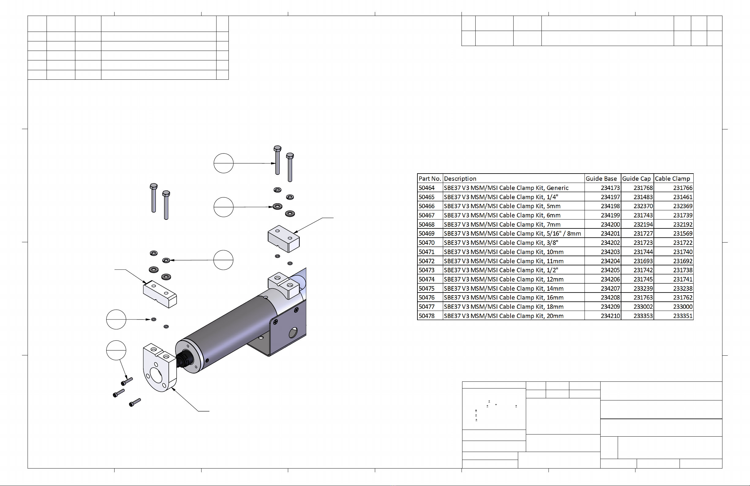
CLAMP/CAP/BASE SUB-ASSEMBLY COMPONENTS (as seen in attached drawing, 67094E)
SBE P/N
Manufacturer P/N
Primary SBE Application
QTY
30633
Washer, 1/4" Split Ring, Ti
Used with cable guide cap and cable clamp securing bolts
2
30634
Washer, 1/4" Flat, Ti
Used with cable guide cap and cable clamp securing bolts
2
30900
Mach Screw, 1/4-20x2" Hex Ti
Secure cable guides/clamps to end caps
2
31019
O-Ring, 2-008 N674-70
Placed on cable clamp 1/4-20 bolts as retainers
2
KIT PART NUMBERS
SBE P/N Kit Description
50465
SBE37 Modular Cable Clamp Kit, ¼”
50472
SBE37 Modular Cable Clamp Kit, 11mm
50466
SBE37 Modular Cable Clamp Kit, 5mm
50473
SBE37 Modular Cable Clamp Kit, ½”
50467
SBE37 Modular Cable Clamp Kit, 6mm
50474
SBE37 Modular Cable Clamp Kit, 12mm
50468
SBE37 Modular Cable Clamp Kit, 7mm
50475
SBE37 Modular Cable Clamp Kit, 14mm
50469
SBE37 Modular Cable Clamp Kit, 5/16” / 8mm
50476
SBE37 Modular Cable Clamp Kit, 16mm
50470
SBE37 Modular Cable Clamp Kit, 3/8”
50477
SBE37 Modular Cable Clamp Kit, 18mm
50471
SBE37 Modular Cable Clamp Kit, 10mm
50478
SBE37 Modular Cable Clamp Kit, 20mm
DATE REV REVISION RECORD AUTH DR CHK
06.03 B Added new 7mm Kit CB MJ
03.04 C Updated Drawing Revision KLP
7.9.04
D
Change title
CB
KLP
2.15.05 E Add Clamp/Cap/Base components table
and rework of assy. Instructions. MJ KHH MJ
4.4.06 F Add new kit to List CB MJ
8.30.10 G Updated for 37 V3 CB PC
SBE DRAWING: 67094
TITLE: SBE37SI/SM Microcat V3 Cable
Guide/Clamp Assembly
REV: .05
Sea-Bird Electronics Procedure
PROCEDURE NUMBER: 67094
TITLE: SBE37 SM/SI V3 Cable Clamp Kit Assembly
REVISION: G
EFFECTIVE DATE: 8/30/2010
CHECKED BY: PC PAGE 2 of 3
S E A
-
BIR D E LE CTR O NIC S, INC.
13431 NE 20th St., Bellevue, Washington 98005 USA
Telephone: (425) 643-9866 Telex: 292915 SBEI UR
Fax: (425) 643-9954 Email: seabird@seabird.com
C
Cl
la
am
mp
p/
/C
Ca
ap
p/
/B
Ba
as
se
e
A
As
ss
se
em
mb
bl
ly
y
-
-
U
Us
su
ua
al
ll
ly
y
D
Do
on
ne
e
a
at
t
S
Se
ea
ab
bi
ir
rd
d
1. One (1) Microcat Threaded Insert (231481) must be glued into each hole in the connector endcap
Cable Guide Base (PN varies).
a. Clean the surfaces of the Celcon and of the threaded insert with alcohol.
b. Use a fine grit sandpaper to roughen the celcon surface area.
c. Prime the Celcon with DC-1200.
•Follow instructions on the can.
•DC-1200 has a cure time of about 30 minutes.
d. Use RTV 734 flowable to glue the insert into position.
2. Mate the cable guide cap to the cable guide base to achieve alignment of the threaded inserts
while the RTV cures.
a. Align them together so that the circular cut-outs make a hole.
b. Use one (1) bolt (30900) for every insert to align them while they cure.
c. Slide the bolts into the guide cap from the rounded side.
3. RTV cures at an absolute minimum of 2 hours, but should be allowed to cure overnight.
4. Once the RTV has fully cured, you may remove the cable guide cap.
5. Secure the guide cap to the guide base.
a. Align them together so that the circular cut-outs make a hole.
b. Place one lock washer (30633) and one flat washer (30634) onto each of the two (2) bolts
(30900).
c. Slide the bolts into the guide cap from the rounded side.
d. Slide one (1) o-ring (31019) over each bolt.
e. Secure the guide cap to the guide base with these bolts. The o-rings should seat themselves
into the internal countersinks on the blocks.
I
In
ns
st
ta
al
ll
l
S
Se
en
ns
so
or
r
E
En
nd
dc
ca
ap
p
C
Ca
ab
bl
le
e
C
Cl
la
am
mp
p
A
As
ss
se
em
mb
bl
ly
y
1. Install the first clamp guide piece (one of the two identical blocks) onto the endcap.
a. Align it so that the threaded circular cut-out faces away from the sensor.
b. Secure onto the endcap with one (1) cap screw (31873) and one (1) lock washer (30867).
2. Install the second clamp piece to the first piece.
a. Align them so that the circular cut-outs make a hole.
b. Place one lock washer (30633) and one flat washer (30634) onto each of two (2) bolts
(30900).
c. Slide the screws into the cable clamp from the flat side.
d. Slide one o-ring (31019) over each bolt.
e. Secure the cable clamps together with these bolts. The o-rings should seat themselves into the
internal countersinks on the blocks.
SBE DRAWING: 67094
TITLE: SBE37SI/SM Microcat V3 Cable
Guide/Clamp Assembly
REV: .05
Sea-Bird Electronics Procedure
PROCEDURE NUMBER: 67094
TITLE: SBE37 SM/SI V3 Cable Clamp Kit Assembly
REVISION: G
EFFECTIVE DATE: 8/30/2010
CHECKED BY: PC PAGE 3 of 3
S E A
-
BIR D E LE CTR O NIC S, INC.
13431 NE 20th St., Bellevue, Washington 98005 USA
Telephone: (425) 643-9866 Telex: 292915 SBEI UR
Fax: (425) 643-9954 Email: seabird@seabird.com
I
In
ns
st
ta
al
ll
l
C
Co
on
nn
ne
ec
ct
to
or
r
E
En
nd
dc
ca
ap
p
G
Gu
ui
id
de
e
C
Ca
ap
p
a
an
nd
d
B
Ba
as
se
e
1. The guide base installs onto the connector endcap with the rounded side containing the
countersunk screw holes facing away from the sensor, and squared end facing the same direction
as the clamp guides on the other end.
2. Secure the guide base to the endcap with three (3) cap screws (31066) directly into the endcap,
a. Coat the screws in NeverSeez.
R
Re
e-
-I
In
ns
st
ta
al
ll
li
in
ng
g
t
th
he
e
C
Co
on
nn
ne
ec
ct
to
or
r
E
En
nd
dc
ca
ap
p
1. If you have removed the sensor endcap, either for this procedure, or to replace the batteries,
please follow this procedure to properly re-install the endcap.
2. Inspect, clean and re-lubricate the seating surface as necessary.
3. Insert the molex header onto the pins on the battery post.
4. Verify visually that the pins are properly aligned. Microcats have “burned up” before because of
the pins have been misalignment.
5. Install the endcap carefully, but tightly, onto the housing, so that the screw holes are both aligned.
6. Inject the holes with DC-4, and secure the housing to the endcap with the screws that were
removed.
3
4
1
4
2
4
4
4
Cable Guide Cap
Cable Clamp
Cable Guide Base
5
3
REV.
DATE
ZONE
DESCRIPTION
AUTH
DWG
CHK
.05
2/14/2011
Updated for SBE37 V3
CB
PC
ITEM
NO.
PART
NUMBER
DRAWING
NUMBER
DESCRIPTION
QTY.
1 30633
N/A
Washer, 1/4" Split Ring Lock, Titanium
4
2 30634
N/A
Washer, 1/4" Flat, Titanium
4
3 30900
N/A
Mach Screw, 1/4-20 X 2" Hex Head Titanium
4
4 31019
N/A
O-ring, Parker 2-008 N674-70
4
5 31066
N/A
Cap Screw, 8-32 X 3/4 Socket Head, Titanium
3
C
B
A
A
B
C
D
1
2
3
4
5
6
7
8
8
7
6
5
4
3
THE INFORMATION CONTAINED IN THIS
DRAWING IS THE SOLE PROPERTY OF
SEA-BIRD ELECTRONICS, INC. ANY
REPRODUCTION IN PART OR AS A WHOLE
WITHOUT THE WRITTEN PERMISSION OF
SEA-BIRD ELECTRONICS, INC. IS PROHIBITED.
PROPRIETARY AND CONFIDENTIAL
DIMENSIONS ARE IN INCHES
TOLERANCES:
FRACTIONAL
1/x
ANGULAR:
0.5
BEND
.X
.05 TYP RAD .01
.XX
.01
.XXX
.003
MACHINED SURFACES
INTERPRET GEOMETRIC TOLERANCING
PER: ANSI Y14.5M - 1994
MATERIAL
FINISH
N/A
DRAWN
COMMENTS:
DATE
NAME
TITLE:
SIZE
B
DWG. NO.
SCALE: 1:3
UNLESS OTHERWISE SPECIFIED:
SBE37SI/SM Microcat V3 Cable Guide/Clamp Assembly
SHEET 1 OF 1
67094.05
DO NOT SCALE DRAWING
SEA-BIRD ELECTRONICS, INC.
13431 NE 20th Street, Bellevue, WA 98005
425-643-9866
PART NO.
DEBUR AND BREAK
SHARP EDGES
See Table
N/A N/A
Old Part/Draw Info
PC
02/14/11
/
1
2
D
N/A

Popular Cables And Connectors manuals by other brands

Multi-Contact FL3-SG-24+PE/ PA Series Assembly instructions

Multi-Contact

Multi-Contact FL3-SG-24+PE/ PA Series Assembly instructions

Monoprice MP-SP07D operating instructions

Monoprice

Monoprice MP-SP07D operating instructions

Safe Fleet RGY Button quick start guide

Safe Fleet

Safe Fleet RGY Button quick start guide

Panduit Opti-Core Specification sheet

Panduit

Panduit Opti-Core Specification sheet

ELEY 1045 Assembly/installation instructions

ELEY

ELEY 1045 Assembly/installation instructions

Einstein The Flash manual

Einstein

Einstein The Flash manual

CommScope ION-M7P manual

CommScope

CommScope ION-M7P manual

Atim Cloud Wireless ACW/LW8-DINRSM user guide

Atim Cloud Wireless

Atim Cloud Wireless ACW/LW8-DINRSM user guide

GridConnect NetDirect user guide

GridConnect

GridConnect NetDirect user guide

geratech EGE-UHD-5HDB-1431 manual

geratech

geratech EGE-UHD-5HDB-1431 manual

Philips SDW5010 Specifications

Philips

Philips SDW5010 Specifications

CYP CH-526RXPL Operation manual

CYP

CYP CH-526RXPL Operation manual

Philips SWV3472W Specifications

Philips

Philips SWV3472W Specifications

Emerson Rosemount 356 Reference manual

Emerson

Emerson Rosemount 356 Reference manual

Tellur TLL321031 user manual

Tellur

Tellur TLL321031 user manual

PCB Piezotronics 034F50 Installation and operating manual

PCB Piezotronics

PCB Piezotronics 034F50 Installation and operating manual

Staubli PV-KBT4/5 UR Series Assembly instructions

Staubli

Staubli PV-KBT4/5 UR Series Assembly instructions

DIW DSR-2300 Quick user guide

DIW

DIW DSR-2300 Quick user guide

manuals.online logo
manuals.online logoBrands
  • About & Mission
  • Contact us
  • Privacy Policy
  • Terms and Conditions

Copyright 2025 Manuals.Online. All Rights Reserved.