SBS VME-TB21 User manual

Artisan Technology Group is your source for quality
new and certied-used/pre-owned equipment
• FAST SHIPPING AND
DELIVERY
• TENS OF THOUSANDS OF
IN-STOCK ITEMS
• EQUIPMENT DEMOS
• HUNDREDS OF
MANUFACTURERS
SUPPORTED
• LEASING/MONTHLY
RENTALS
• ITAR CERTIFIED
SECURE ASSET SOLUTIONS
SERVICE CENTER REPAIRS
Experienced engineers and technicians on staff
at our full-service, in-house repair center
WE BUY USED EQUIPMENT
Sell your excess, underutilized, and idle used equipment
We also offer credit for buy-backs and trade-ins
www.artisantg.com/WeBuyEquipment
REMOTE INSPECTION
Remotely inspect equipment before purchasing with
our interactive website at www.instraview.com
LOOKING FOR MORE INFORMATION?
Visit us on the web at www.artisantg.com for more
information on price quotations, drivers, technical
specications, manuals, and documentation
Contact us: (888) 88-SOURCE | sales@artisantg.com | www.artisantg.com
SM
View
Instra

VME-TB21
Peripheral Transition Board
User’s Manual
Copyright © 1999-2003 by SBS Technologies, Inc.
*9100-51-036-B0*
Artisan Technology Group - Quality Instrumentation ... Guaranteed | (888) 88-SOURCE | www.artisantg.com

VME-TB21 User’s Manual
Document Number A-933-MN-02550-B0
Part Number 9100-51-036-B0
Revision By Date Comments
00 dlb 07-01-94 Initial release
01 dlb 02-06-96 Minor correction
A0 dlb 06-03-96 Update for board rev. A0
B0 jev 11-17-99 Update for board rev. B0
B0 jev 5-15-2003 Update for minor changes and current Logos
The information contained within this document has been carefully checked and
is believed to be entirely reliable and consistent with the product that it
describes. However, no responsibility is assumed for inaccuracies. Nor does
SBS Technologies, Inc. assume any liability arising out of the application or use
of any product or circuit described herein. SBS Technologies reserves the right
to make changes to any product and product documentation in an effort to
improve performance, reliability, or design. Furthermore, the information con-
tained herein is of a proprietary nature and is not to be reproduced without prior
written consent of SBS Technologies, Inc.
IBM, PC/AT, and AT are trademarks of International Business Machines
Corporation.
A number of conventions are used throughout this manual in order to provide
clarity and accuracy. These include:
• The use of an ‘H’ suffix to a number indicates that the number is written in
hexadecimal (base sixteen) notation.
• The use of a ‘-’ (minus) suffix to a signal name indicates that it is an active
low signal. The signal is either true when the signal is at a logic zero level or
the signal initiates actions on a high-to-low transition.
• Text in Courier Font indicates a command entry or output from an SBS
embedded PC product using its built-in character set.
Document Information
Revision History
Disclaimer
Trademarks
Conventions
Artisan Technology Group - Quality Instrumentation ... Guaranteed | (888) 88-SOURCE | www.artisantg.com

Contents
General Description 1
Features 1
Connector Locations 1
P2 Peripheral Interface 2
Floppy Drive Interface 4
SCSI Interface 5
IDE Drive Interface 6
Installation 8
Specifications 8
Tables
Table 1: P2 Peripheral Interface Signals 3
Table 2: Floppy Drive Interface Signals 4
Table 3: SCSI Interface Signals 6
Table 4: IDE Drive Interface Signals 7
Figures
Figure 1: Location of TB21 Connectors 1
Figure 2: P2 Peripheral Interface Connector Pin Locations 2
Figure 3: Floppy Interface Connector Pin Locations 4
Figure 4: SCSI Connector Pin Locations 5
Figure 5: IDE Interface Connector Pin Locations 6
Figure 8: TB21 Installation 8
Contents iii
Artisan Technology Group - Quality Instrumentation ... Guaranteed | (888) 88-SOURCE | www.artisantg.com

This page intentionally left blank
Artisan Technology Group - Quality Instrumentation ... Guaranteed | (888) 88-SOURCE | www.artisantg.com
The VME-TB21 transition board is a companion to SBS Technologies VME-
2486, V5x, and PROx series Embedded PCs which provides a convenient
means of connecting remotely-mounted floppy drives, hard drives, and other
peripherals. The VME-TB21 routes the peripheral control signals supplied by
the aand crows of the Embedded PC’s P2 connector to standardized connec-
tors which are compatible with industry-standard signal definitions. The VME-
TB21 simply plugs onto the back of the P2 backplane in the slot position occu-
pied by the CPU card. Only the signals provided on P2 rows aand c, and power
(+5V/GND) from row b are utilized by the TB21. The extended VMEbus signals
on row bare not connected.
The VME-TB21 has a number of features which make it an excellent companion
to SBS Embedded Computers VME-2486, V5x, and PROx Embedded PCs:
• Directly Plug Compatible with VME-2486, V5x, and PROx series
• Connection to Floppy, IDE and SCSI
• Provides P2 Peripheral Interface Connector for SBS Drive Modules
NOTE: Power Connectors are not available on the VME-TB21.
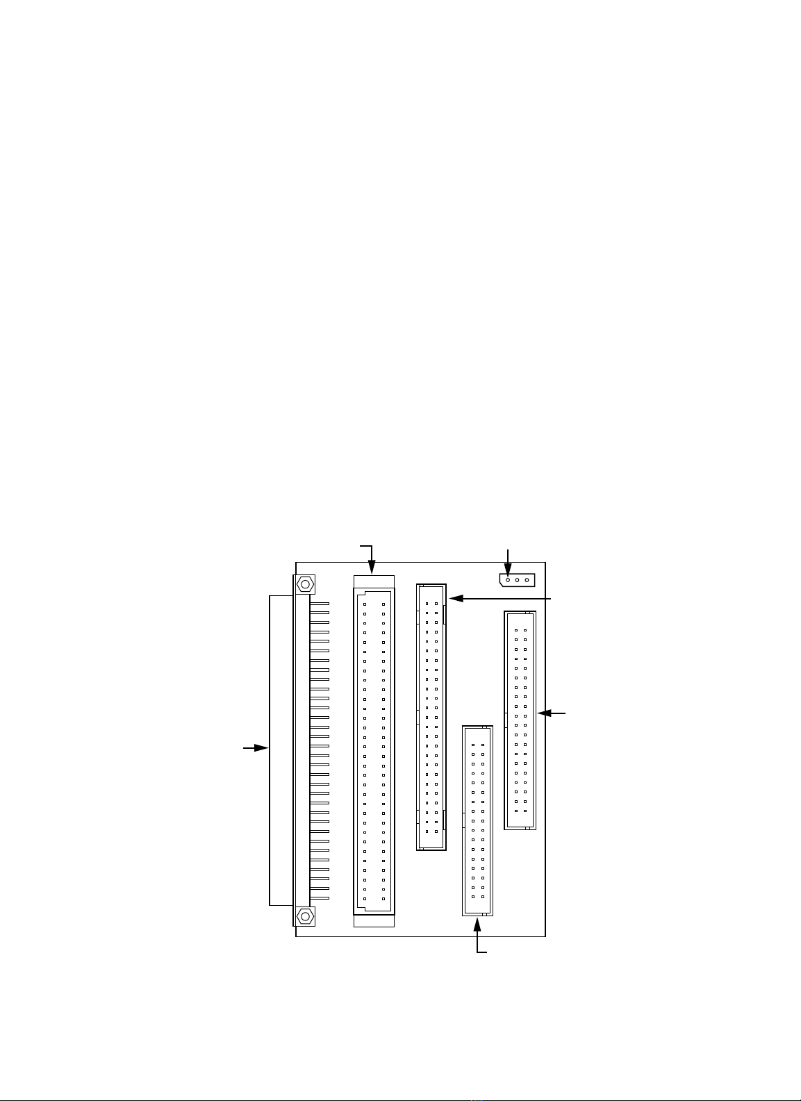
The location of each connector of the VME-TB21 is shown in Figure 1.
VME-TB21 User’s Manual 1
General Description
Features
Connector Locations
P2 Peripheral Interface Connector
P2 VME Interface
Connector
Floppy Drive Interface Connector
SCSI Interface Connector
IDE Hard Disk
Interface Connector
J1
Pin 1
Figure 1 Location of TB21 Connectors
Artisan Technology Group - Quality Instrumentation ... Guaranteed | (888) 88-SOURCE | www.artisantg.com
VME-TB21 User’s Manual
2
P2 Peripheral Interface The P2 peripheral interface is provided to a three-row eurocard socket connec-
tor labeled P1 which has the center row, row b, not installed. As such, it does
not pass the extended VME signals found on P2 row b, but provides the SCSI,
IDE, and floppy drive signals found on P2 rows aand c. With this interface,
you can use a TB21 with your Embedded PC and still connect a SBS
Technologies VME-6200 drive module.
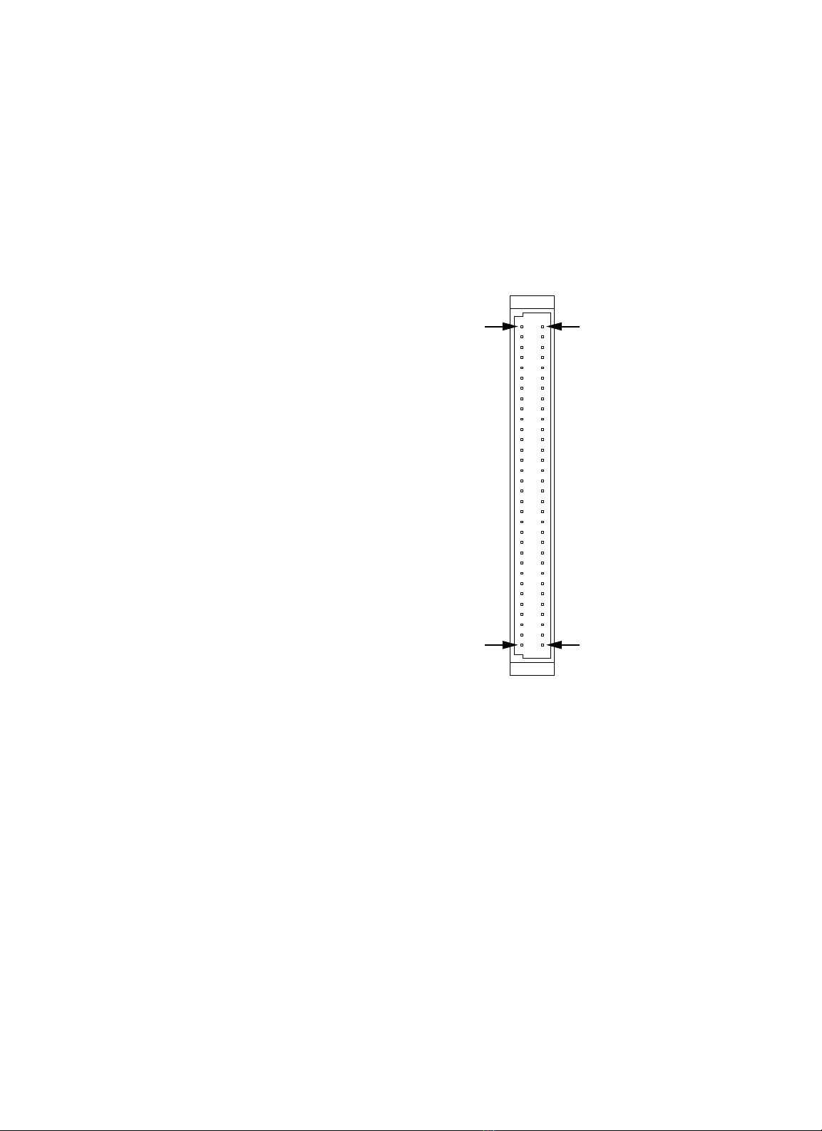
Figure 2 shows the pin numbering of the connector. Table 1 shows the signals
provided by the P2 peripheral interface.
Figure 2 P2 Peripheral Interface Connector Pin Locations
Pin C1
Pin C32 Pin A32
Pin A1
Artisan Technology Group - Quality Instrumentation ... Guaranteed | (888) 88-SOURCE | www.artisantg.com

VME-TB21 User’s Manual 3
Pin Number Row c Pin Row a Pin
1 HDMACK- DB0
2 HD0 DB1
3 HD1 DB2
4 HD2 DB3
5 HD3 DB4
6 HD4 DB5
7 HD5 DB6
8 HD6 DB7
9 HD7 PARITY-
10 HD8 ATN-
11 HD9 BSY-
12 HD10 ACK-
13 HD11 RST-
14 HD12 MSG-
15 HD13 SEL-
16 HD14 C/D-
17 HD15 REQ-
18 PDIAG I/O-
19 HDIOW- HSMARQ
20 HDIOR- FRWC-
21 IOCHRDY FINDEX-
22 HDALE FMTO-
23 IRQ14 FDS2-
24 IOCS16- FDS1-
25 HDA0 FMT1-
26 HDA1 FDIRC-
27 HDA2 FSTEP-
28 HCS0- FWD-
29 HCS1- FWE-
30 SLVACT- FTK0-
31 FHS- FWP-
32 FDSKCHG- FRD-
Table 1 P2 Peripheral Interface Signals
Artisan Technology Group - Quality Instrumentation ... Guaranteed | (888) 88-SOURCE | www.artisantg.com

VME-TB21 User’s Manual
4
The floppy drive interface is provided to a 34-position male header connector
(AMP part 103308-7 or equivalent) which will accept most standard floppy
cable assemblies. The connector is labeled “FLOPPY” on the TB21 silkscreen
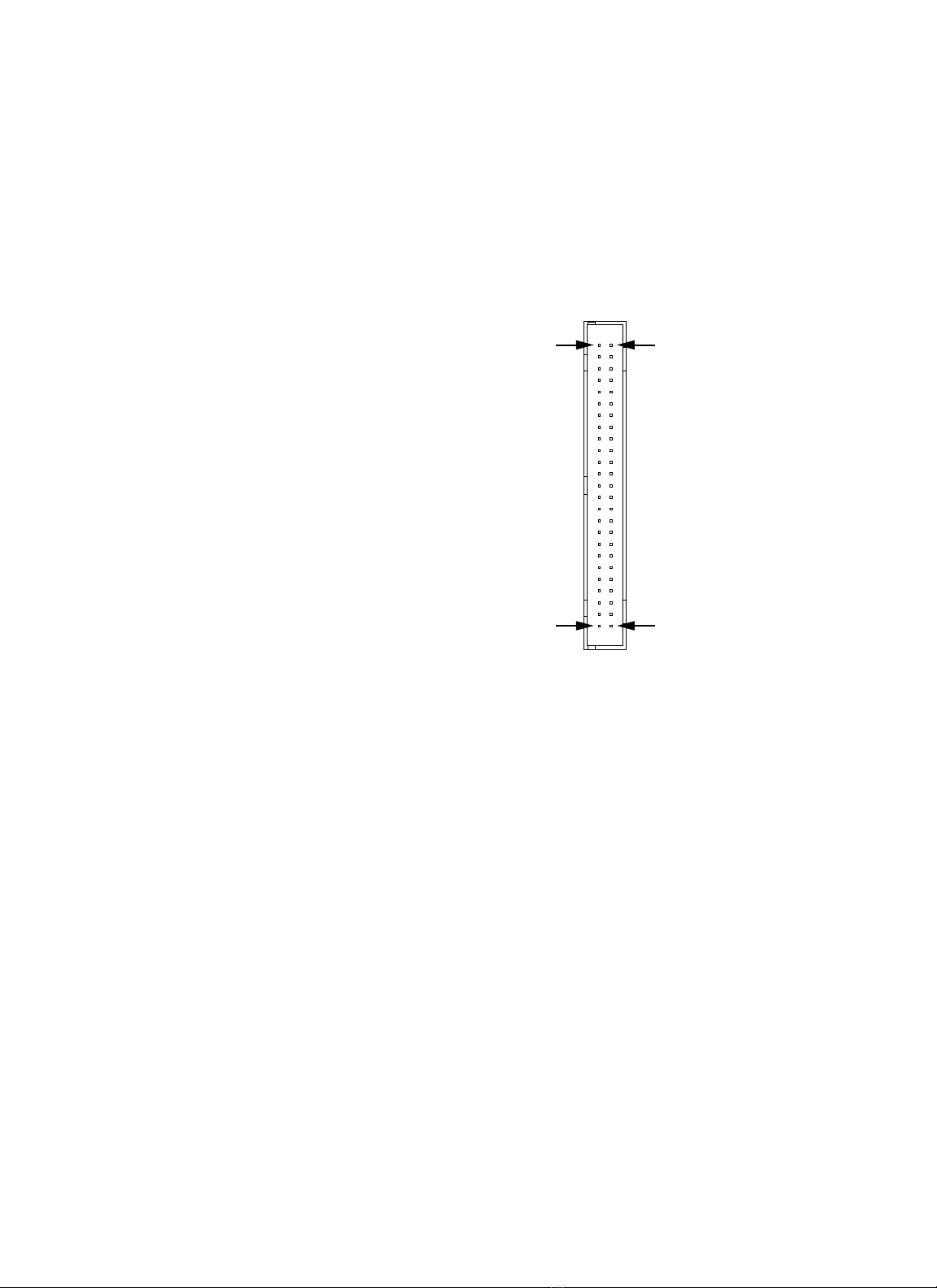
and is component P3. Figure 3 shows the pin numbering of the connector. Table
2 shows the signals provided by the floppy interface.
Figure 3 Floppy Interface Connector Pin Locations
Pin 1
Pin 33 Pin 34
Pin 2
P3 Pin Signal Direction Signal Description
Odd GND Signal Ground
2 FRWC- To Drive Read/Write Control
4 NC Not Connected - Unused
6 NC Not Connected - Unused
8 FINDEX- From Drive Index Mark Detected
10 FMT0- To Drive Motor On 0
12 FDS2- To Drive Drive Select 2
14 FDS1- To Drive Drive Select 1
16 FMT1- To Drive Motor Control 1
18 FDIRC- To Drive Step Motor Direction Control
20 FSTEP- To Drive Motor Step Control
22 FWD- To Drive Write Data
24 FWE- To Drive Write Enable
26 FTK0- From Drive Track 0 Position
28 FWP- From Drive Floppy is Write Protected
30 FRD- From Drive Read Data
32 FHS- To Drive Head (Side) Select
34 FDSKCHG- From Drive Disk Change Indicator
Table 2 Floppy Drive Interface Signals
Floppy Drive Interface
Artisan Technology Group - Quality Instrumentation ... Guaranteed | (888) 88-SOURCE | www.artisantg.com
The SCSI hard disk interface is provided by a 50-position male header connec-
tor which will accept most standard SCSI drive ribbon cable assemblies. This
connector is labeled P4 and Figure 4 shows the pin locations of the connector.
The signals provided by the SCSI interface are shown in Table 3.
Note: Termination power is provided by the TB21 if the TB21 is being supplied
power via the power supply connector.
VME-TB21 User’s Manual 5
SCSI Interface
Figure 4 SCSI Connector Pin Locations
Pin 1
Pin 49 Pin 50
Pin 2
Artisan Technology Group - Quality Instrumentation ... Guaranteed | (888) 88-SOURCE | www.artisantg.com
Table of contents


