Scallop Imaging A division of Tenebræx Corporation 27 Drydock Avenue, Boston, MA 02210 USA 617.849.6400
© 2011 Tenebræx Corporation Specifications subject to change without notice. US Patent No. 7,262,789, other patents pending. 20110322
www. callopimaging.com
4.5”
(114.5mm)
8”
(204mm)
4.4”
(112mm)
2”
(51mm)
2.5”
(63.5mm)
2.9”
(73.66mm)
2.25”
(57mm)
1”
(25.1mm)
2”
(51mm)
A bir control spike is
included in this Outdoor
Housing package. It’s
use is optional and is
intended to discourage
birds from perching or
nesting on your A7 or
D7 Camera.
The bird control spike
has a double sided
adhesive pad attached
to the bottom. Make
sure the housing is clean and free of grease and
dirt. Carefully peel back the non-adhesive side
and apply to the top of the camera housing. It
can also be applied to the nose shield.
Do not use mechanical fasteners or drill into the
outdoor housing as that will compromise the
weatherproof protection and void your warranty.
When using the USB cable for setup
You have the option of using either Phillips or Tamper-resistant
screws to attach the cover to the housing.
If using Phillips screws for final assembly
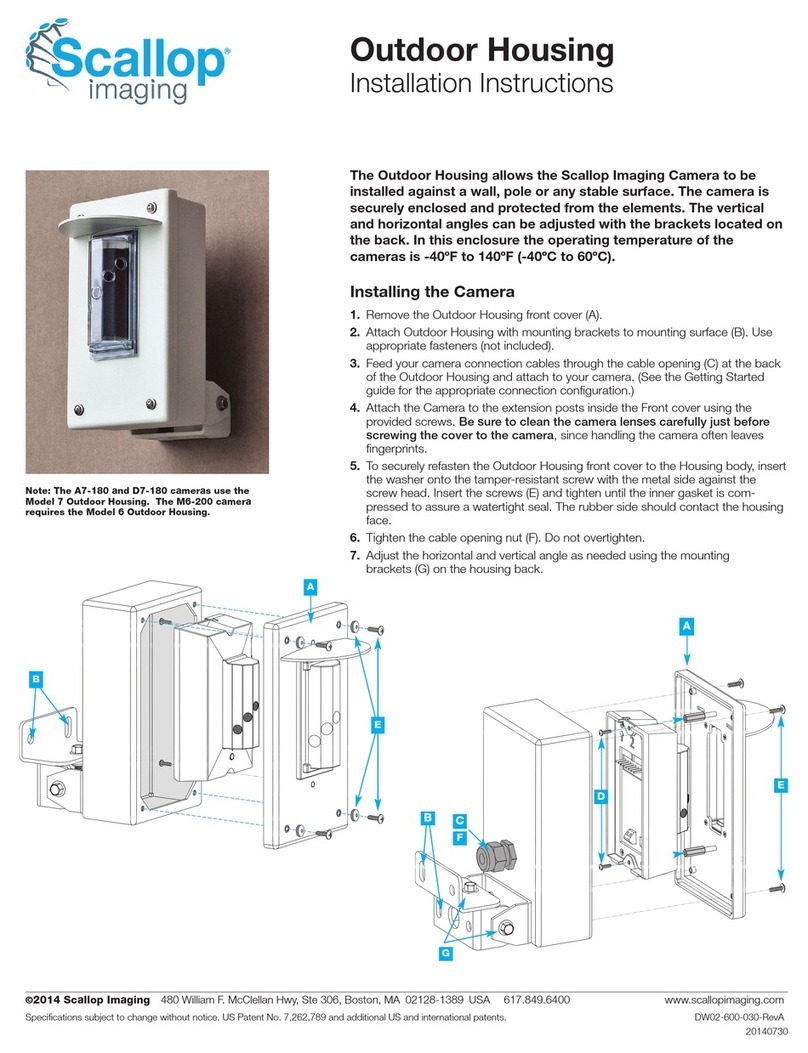
1. Slide the sealing washers onto the four 1½” Phillips head screws.
2. Plug the USB cable into the camera, place the front cover onto the
housing and start the four screws into the housing.
3. Pull the front cover back to allow space to slide the 2 clear spacers
(A) shown in blue) so they sit on the screws.
4. Push the front cover against the spacers and lightly tighten the 4
screws to hold the spacers in place.
5. Set the camera adjustments using the USB application.
6. hen adjustments are complete, loosen the 4 screws, remove the
spacers and remove the USB cable.
7. Tighten the 4 screws until the front cover is sealed against the
housing.
If using Tamper-resistant screws for final assembly
1. Use the four 1½” Phillips head screws.
2. Plug the USB cable into the camera, place the front cover onto the
housing and start the four screws into the housing.
3. Pull the front cover back to allow space to slide the 2 clear spacers
(A) shown in blue) so they sit on the screws.
4. Push the front cover against the spacers and lightly tighten the 4
screws to hold the spacers in place.
5. Set the camera adjustments using the USB application.
6. hen adjustments are complete, remove the 4 Phillips head screws
and spacers.
7. Remove the USB cable.
8. Slide the sealing washers onto the four 1” Tamper-resistant screws.
9. Insert and tighten the 4 Tamper-resistant screws using the provided
driver until the front cover is sealed against the housing.
A A
A
A
A USB A to a Down Angle
Mini-B cable (not included)
i needed in order to
connect the camera and et
the camera adju tment
u ing the USB application.


