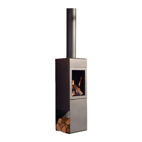
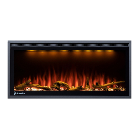
scandia AVEDUR SCGAS10 User manual

AVEDUR
OWNERS MANUAL
Scandia Heating (Aust) Pty Ltd
Head Office
306 South Gippsland Highway
Dandenong South VIC 3175
Australia
Warehouse
Lot 1 Melbourne Cresent,
Seymore VIC 3660
Australia
+61 3 5792 2388
www.scandiastoves.com.au
Model Name Avedur
Model Number SCGAS10

Introduction 1
Safety precautions 2
Compliance plate 3
Your heater at a glance 4
Product dimensions 5
Installation guide
- Clearances to combustibles 6
- Flue installation 8
- Prohibited area for flue terminals 9
- Media installation procedure 11
- Gas type conversion 13
- Fascia installation 14
- App control WiFi module installation 15
- Installation checklist 15
Operating instructions
- Remote control instructions 16
- App control overview and operation 19
Heater maintenance
- Routine maintenance schedule 21
- Component access 22
Troubleshooting 24
Wiring diagram 25
Avedur exploded diagram 26
Spare part list 27
Media spare parts list 28
Warranty 29
CONTENTS
INTRODUCTION
Congratulations on purchasing a genuine Scandia gas space heater. When cared for properly, these high quality, finely crafted gas space heaters
will offer many years of reliable performance. This instruction manual has been developed to ensure optimum performance from your Scandia
gas space heater. It’s very important that you thoroughly read and understand all instructions before using your new heater.
COUNCIL REQUIREMENTS
Check Local Council Requirements Eg. permits
When installing, operating and maintaining your gas space heater, follow the guidelines presented in these instructions,
and make them available to anyone using or servicing the gas space heater.
Your city, town, state or territory may require a building permit to install a gas space heater.
Always consult your local building inspector or local council to determine what regulations apply in your area.
Your gas space heater must be installed by a qualified person whose
work conforms with local council regulations, Australian standards
&manufacturers recommendations. Failure to do so willvoid your
warranty and could possibly void any home insurance.
Please note:
1.

1. DO NOT PLACE ARTICLES ON OR AGAINST THIS APPLIANCE.
2. DO NOT USE OR STORE FLAMMABLE MATERIAL NEAR THE APPLIANCE.
3. DO NOT SPRAY AEROSOLS IN THE VICINITY OF THIS APPLIANCE WHILST IT IS IN OPERATION.
4. DO NOT MODIFY THIS APPLIANCE.
5. NOT SUITABLE TO BE INSTALLED IN A MARINE ENVIRONMENT.
INSTALLATION NOTICE
1. INSTALLATION AND SERVICE MUST BE PERFORMED BY A QUALIFIED INSTALLER, SERVICE AGENCY
OR THE GAS SUPPLIER.
2. INSTALLATION OF THIS APPLIANCE IS ONLY TO BE CARRIED OUT IN ACCORDANCE WITH
THE MANUFACTURER’S INSTRUCTIONS, LOCAL GAS FITTING REGULATIONS, AS56012004
INSTALLATION CODE FOR GAS BURNING APPLIANCES AND ANY OTHER RELEVANT STATUTORY
REGULATIONS.
WARNING
1. THE SCANDIA AVEDUR HAS A PRIMARY SAFETY GUARD FITTED IN FRONT OF THE GLASS DOOR.
THIS SAFETY GUARD IS FITTED TO REDUCE THE RISK OF INJURY FROM BURNS AND AT NO TIME
SHOULD THIS GUARD BE PERMANENTLY REMOVED.
2. GLASS AND OTHER SURFACES ARE HOT DURING OPERATION AS WELL AS DURING THE COOLING
DOWN PERIOD. PRECAUTION SHOULD BE TAKEN AND YOUNG CHILDREN MUST BE SUPERVISED AT
ALL TIMES.
NOTE
1. A SLIGHT SMELL MAY BE APPARENT FOR THE FIRST FEW HOURS OF USE. THIS IS DUE TO THE HEAT
RESISTANT PAINT CURING. IT IS RECOMMENDED TO OPEN WINDOWS IN THE ROOM FOR THE FIRST
LIGHTING OF THE FIRE. IN SOME INSTANCES, A SLIGHT DISCOLOURATION MAY OCCUR INSIDE THE
FIREBOX, THIS IS A NORMAL CONDITION AND IS NOT COVERED BY WARRANTY.
IF YOU SMELL GAS
1. DO NOT TRY TO LIGHT THE APPLIANCE.
2. DO NOT TOUCH ANY ELECTRICAL SWITCHES NEAR THE APPLIANCE.
3. DO NOT USE YOUR PHONE IN THE VICINITY OF THE APPLIANCE.
4. IMMEDIATELY CALL YOUR GAS SUPPLIER (NOT IN THE VICINITY OF THE APPLIANCE) AND FOLLOW
THEIR INSTRUCTIONS.
5. IF YOU CANNOT REACH YOUR GAS SUPPLIER, CALL THE FIRE DEPARTMENT.
SAFETY PRECAUTIONS
When properly maintained and operated your gas space heater should give you many years of service,
however there are important safety aspects of these products that you need to be aware of when operating
a gas space heater.
2.

CERTIFICATE HOLDER:
SCANDIA HEATING (AUST) PTY LTD
LOT 1 MELBOURNE CRES, SEYMOUR VIC 3660
PH: 03 5792 2388
COMPLIANCE PLATE
SCANDIA AVEDUR GAS LOG FIRE
SERIAL NO:
MANUFACTURE DATE:
IAPMO APPROVAL NO:
THIS PRODUCT IS TESTED IN ACCORDANCE WITH AS4553-2008 AND AS3100
MADE IN CHINA
NATURAL GAS PROPANE GAS
Inlet gas pressure 1.13 kPa 2.75 kPa
Outlet gas pressure 0.95 kPa 2.41 kPa
Nominal (maximum) gas consumption 25.5 MJ/h 23.0 MJ/h
Turn down gas pressure 0.40 kPa 0.68 kPa
Turn down gas consumption 17.0 MJ/h 12.7MJ/h
Main burner injector 2.3 mm 1.4mm
Primary aeration opening 15mm Fully open
Electrical requirements 220-240V/50Hz
GMK10437
3.
COMPLIANCE PLATE

REMINDER:
This gas space heater should only be installed by an authorised technician in accordance with:
- AS/NZ 5601.1: Gas Installation Code
- Manufacturers installation instruction
- Local gas fitting regulations
- Municipal building codes.
1. Gas space Heater
2. Fascia (Metallic Black)
3. Remote Control
4. App Control Module (Optional accessory)
5. Media (Driftwood Log Set with Vermiculite)
6. Propane Conversion Kit
7. Owners Manual
1
2
34
5
6
7
4.
YOUR HEATER AT A GLANCE
PROPANE
CONVERSION
KIT
AVEDUR
OWNERS MANUAL
ScandiaHeating(Aust) Pty Ltd
HeadOffice
306SouthGippsland Highway
DandenongSouthVIC 3175
Australia
Warehouse
Lot1MelbourneCresent,
SeymoreVIC3660
Australia
+6135792 2388
www.scandiastoves.com.au
ModelName Avedur
ModelNumber SCGAS10

443
1235
608272
1075
952
445
86
986
20
66
FASCIA
20
1235
992
608
366
5.
51
165
149
Gas Connection
(1/2” Male Thread)
Electrical
Connection
HEATER
PRODUCT DIMENSIONS (mm)

INSTALLATION GUIDE
CLEARANCES TO COMBUSTIBLES
It is extremely important that you respect required installation distances and that you respect local installation regulations.
This is for your safety! The manufacturer is not responsible for the product, if it is not installed following these recommendations.
A combustible surface is anything that can burn (i.e. plaster, wall paper, wood, fabrics etc.) These surfaces are not limited to those that are visible
and also include materials that are behind non-combustible materials. If you are not sure of the combustible nature of a material, consult your
local fire officials.
Minimum clearance for a combustible surface
Please note:
Illustrations and photos reflect typical installations and are for design purposes only. Illustrations/diagrams are not drawn to scale. Actualproduct may vary from pictures in manual.
6.
ASide of the heater 30mm
BBack of the heater 30mm
CDistance from flue pipe 25mm
DTop of the heater 86mm
EFloor below the heater 0mm
D
E
A
C
B
Please do not insert screws in
the shaded area as you could
damage the components
within the heater.

INSTALLATION GUIDE
CLEARANCES TO COMBUSTIBLES...continued
Minimum Framing Dimensions
ARough opening (vent pipe) 220mm
BRough opening (height) 1100mm
CRough opening (depth) 470mm
DRough opening (width) 1300mm
7.
Minimum clearance for a combustible surface
A
Mantel height from top of the
fireplace opening (mm) 360mm
BSide Wall 80mm
CCeiling 1000mm
DMantel Depth (max) 330mm
EFront floor (non-combustible) 0mm
FAlcove depth 915mm
GIsolation switch max distance 1000mm

IMPORTANT:
Your Scandia gas space Heater must be vented directly to the outside.
Vertical (V) Horizontal (H)
Minimum 1x 900mm flue pipes -
Maximum 6x 900mm flue pipes 1800mm
Note: Duravent flue products must be used for all installations.
Ensure that flue configuration is consistent with
the requirements specified in the below table.
8.
INSTALLATION GUIDE
FLUE INSTALLATION
Vertical Vent Flue Installation
Rear Vent Flue Installation
Horizontal (H) Vertical (V)
1 x 90 Elbow + 1 x 900mm flue pipe
1 x 90 Elbow + 1 x 900m flue pipe + 1 x 900mm flue pipe
1 x 90 Elbow + 3 x 900m flue pipe + 2 x 900mm flue pipe
1 x 90 Elbow + 4 x 900m flue pipe + 2 x 900mm flue pipe
Note: Duravent flue products must be used for all installations.
Ensure that flue configuration is consistent with
the requirements specified in the below table.

T = Flue Terminal I = Mechanical Air Inlet M = Gas Meter P = Electricity meter or fuse box Z = Fan-assisted appliance only
ORANGE SHADING INDICATES PROHIBITED AREA FOR FLUE TERMINALS
PROHIBITED AREA FOR FLUE TERMINALS
9.
INSTALLATION GUIDE

INSTALLATION GUIDE
PROHIBITED AREA FOR FLUE TERMINALS ...continued
Reference Item Min Clearance^
A Below eaves, balconies and other projections
Appliances up to 50 MJ/h input 300mm
Appliances over 50 MJ/h input 500mm
B From the ground, above a balcony or other surface* 300mm
C From a return wall or external corner* 500mm
D From a gas meter (M)* (See Note 3) 1000mm
E From an electricity meter or fuse box (P) #(See Note 3) 500mm
F From a drain pipe or soil pipe 150mm
G Horizontally from any building structure* or obstruction facing a terminal 500mm
H From any other flue terminal, cowl, or combustion air intake* 500mm
J
Horizontally from an openable window, door, non-mechanical air inlet, or any other opening into a building with the exception of sub-floor
ventilation
Appliances up to 150 MJ/h input* 500mm
Appliances over 150 MJ/h input p to 200 MJ/h input* 1500mm
Appliances over 200 MJ/h input up to 250 MJ/h input* 1500mm
Appliances over 250 MJ/h input* 1500mm
K From a mechanical air inlet, including a spa blower 1500mm
N Vertically below an openable window, non mechanical air inlet, or any other opening into a building with the exception of sub-floor ventilation
Space heaters up to 50 MJ/h input 150mm
Other appliances up to 50 MJ/h input 500mm
Appliances over 50MJ/h input and up to 150 MJ/h input 1000mm
Appliances over 150 MJ/h input 1500mm
* Unless appliance is certified for closer installation
^Natural draft flue configuration only
# Prohibited area below electricity meter or fuse box extends to ground level
1. Where dimensions C, J or K cannot be achieved or an equivalent horizontal distance measured diagonally from the nearest discharge point of the terminal to the
opening may be deemed by the technical regulator tocomply.
2. For appliances not addressed above acceptance should be obtained from the technical regulator
3. Minimum clearances D and E also apply to any combustion air intake openings of appliances
Notes
10.

Vermiculite Burner (Default)
105mm 265mm 120mm
Using the vermiculite provided fill the burner up to 10-15mm deep, evenly spread across the tray.
Use 3 Lava rocks provided and place them according to the distances below. *
Glass Burner
105mm 265mm 120mm
Using the glass fill the burner up to 10-15mm deep, evenly spread across the tray.
Use 3 Lava rocks provided and place them according to the distances below. *^
11.
INSTALLATION GUIDE
MEDIA INSTALLATION PROCEDURE
*Lava rock should not be used for propane gas horizontal flue configuration
^Lava rocks should not be used for natural gas horizontal flue configuration

Glass Burner with Drift Wood
Glass Burner with Pebbles
Place the logs and pebbles provided in their designated location. Apart from the burner media, no other log or pebble should
cross the flame. Important: Logs and pebbles should be placed in the same location as depicted in the image below.
Place the pebbles provided in their designated location. Apart from the burner media, no other log or pebble should
crosstheflame. Important: Logs and pebbles should be placed in the same location as depicted in the image below.
Vermiculite Burner with Driftwood (Default)
Vermiculite Burner with Pebbles
Place the logs and pebbles provided in their designated location. Apart from the burner media, no other log or pebble should
cross the flame. Important: Logs and pebbles should be placed in the same location as depicted in the image below.
Place the pebbles provided in their designated location. Apart from the burner media, no other log or pebble should cross
theflame. Important: Logs and pebbles should be placed in the same location as depicted in the image below.
12.
INSTALLATION GUIDE
MEDIA INSTALLATION PROCEDURE ...continued

Inlet
pressure
Outlet
pressure
Max adj.
nut
Min adj. screw
The heater is configured for natural gas by default. Use conversion kit included in packaging to do propane gas type
conversion. Please follow the steps below to convert the heater to propane gas:
STEP 1
STEP 5
STEP 9
STEP 2
STEP 6
STEP 10
STEP 3
STEP 7
STEP 11
STEP 4
STEP 8
Replace the main burner injector using the
injector provided in the conversion kit.
Remove and replace the pilot injector using
the injector provided in the conversion kit.
Remove the selector jumper as shown
in the image below. This will activate the
propane configuration of the control
board.
Using a spanner, remove the nut to access
the pilot injector.
Locate the Millennium control board and
remove three screws as shown in the image
below. Carefully lift the cover to access the
selector jumper inside.
Please refer to the compliance plate/
product specification table to ensure the
correct injector size.
Please refer to the compliance plate/
product specification table to ensure the
correct injector size.
Change the outlet pressure of the gas
valve to suit propane gas type. Inlet and
outlet test points may be used to check the
pressure while doing the adjustments.
Remove two screws and carefully remove
the pilot burner assembly.
Change the primary aeration opening to
suit the propane gas type. Please refer to
the compliance plate/product specification
table to ensure the correct opening size.
A SIT pressure adjustment tool may be used to adjust the pressure. Alternatively a phillip
head screw driver and a 10mm spanner can be used. When adjusting the maximum
pressure, hold the screw driver in place and turn the spanner. When adjusting the
minimum pressure hold the spanner in place and turn the screwdriver.
Main Burner
Injector
Selector
Jumper
Pilot
Injector
13.
INSTALLATION GUIDE
GAS TYPE CONVERSION

14.
INSTALLATION GUIDE
FASCIA INSTALLATION
To remove the fascia, carefully lift and pull away from the heater. The Avedur fascia is designed to accommodate multiple wall finishes of varying depth, when installing, align the
fascia with the locating lugs in the body of the heater insert slowly until the rear of the fascia is in the preferred position, lower the fascia and the mounting mechanism will self-
locateonto lugs. To adjust lift both sides of the fascia evenly and relocate to the desired position. Please note: Some fascia options are heavy and may need additional assistance
when handling.
Avedur fascia is designed to be installed against plain plaster walls or tile/masonry finishing walls. Use the first grove (closest to the front of the fascia) for a standard wall installation.
Use other groves for other wall finishes based on the thickness of the cladding material. There are 3 different extension pieces provided with the heater which will enable the hot air
to flow without restrictions. Use the correct extension piece and install as per the image below if extra cladding material is being used around the fascia.

INSTALLATION CHECKLIST
To control your heater from your mobile phone or tablet from the Scandia Avedur mobile app you need to purchase
theapp control WiFi module. Follow the steps below to install the WiFi module.
The Installation technician must check the following items before leaving the premises.
As shown in the images below, insert the 4 pin plug of the WiFi module into the control board.
15.
Ensure the physical installation is complete including:
Flue installation
Media Installation
Gas type conversion (If required)
Ensure gas inlet and outlet pressure values are set according to the compliance plate
Ensure that a gas leakage (pressure) test is carried out before commissioning the heater
Any other test required by relevant authorities are carried out
Ensure that remote control is paired with the heater (Please refer to remote control instructions, page 19)
Commission the heater and ensure the operation is satisfactory
If you have any problems carrying out any of the tasks above or if the heater operation is not satisfactory, please contact Scandia Heating (Aust) Pty Ltd.
INSTALLATION GUIDE
APP CONTROL WIFI MODULE INSTALLATION

ROOM TEMPERATURE
SET TEMPERATURE, FAN
SPEED & FLAME HEIGHT
TIME OF DAY AND
DAYOF THE WEEK
Remote Display Overview
Feature Symbol Description
Time of day
Displays time of the day in hours and minutes, AM or PM. The time is displayed
when the thermostat is on or off (LCD bottom Time digits)
Day of week
Displays the current day of the week. The day is displayed when the thermostat
is on or off
Temperature Display
Displays the current temperature. Cois the default but Fois available.
Thetemperature range is 7 oC - 32 oC. (Room temperature is displayed onthetop
digits)
Room or set indicator
When the thermostat is ON, the programmed (set) temperature will be
displayed on the centre digits. When the thermostat is off, only the room
temperature (top digits) will be displayed.
Transmit indicator
Indicates that the thermostat is transmitting to the receiver, the symbol will
appear on the LCD for 1 second. When set to ON, the thermostat will transmit
once every 3 minutes (+/- 10 seconds). Also, whenever a button press is made
that will affect the operation of the control unit, the new selection will be
transmitted 3 seconds (+/- 1 second) after the last button pressed.
Battery low indicator
Indicates that battery power is below acceptable level. The symbol will flash to
indicate that the batteries need replacing. The thermostat will remain functional
for approximately another 5 days before shutting off
Programming, Mode, Indication Indicates that the thermostat is in programming mode
Automatic / Manual mode
indication Indicates whether the thermostat is in manual or automatic or flame mode
Flame Indicator
Indicates the flame height
Basic model: the flame will be on or off
Advanced model: the flame ranges from off (no symbol) to 7 graduated flame
settings
Fan Indicator
Indicates the fan speed
Basic model: no fan indicator
Advanced model: The fan ranges from off (no symbol)
to graduated settings 1, 2, 3
9:23 AM
25 c
ROOM
The wireless remote control provided with
your Scandia gas space heater is the primary
controller for all functions (and also operates as
the “in room” thermostat when the appliance is
being controlled by the remote). App control is
also available with the purchase of the optional
app control pack. App control is available for
most mobile devices and can be downloaded
from iTunes and google play store Scandia
recommends fitting the app control pack at
thetime of installation.
16.
OPERATING INSTRUCTIONS
REMOTE CONTROL INSTRUCTIONS

1. With the thermostat off, press and hold the Tbutton for 2 seconds or longer to initiate programming the time. Time, the hour
setting and AM/PM will flash.
Setting The Hour Function
2. Press and release the or button to increase or decrease the hour setting by 1 hour.
Setting the minute function
3. Press and release, or press and hold the or button to increase or decrease the minute setting by 1 minute similarly to the hour
setting. Press OK to accept and select the day of the week.
4. Press and release the or button to change the day of the week to the following or previous day. Press and hold the or
button for 2 seconds or longer to increase or decrease the day of the week by 1 day every 0.5 seconds. Press OK to complete
setting. The time and day of the week is now set.
On/O
Setting The Day Of The Week & Time
Manual Mode
1. Press and release button. If the thermostat is off, pressing and releasing will turn the thermostat on to the most recently
selected working mode.
The manual mode allows setting the temperature at any level. Manual mode does not require that the time and day of the week are set.
Flame height and fan speed
The flame height and fan speed are not manually adjustable. The flame height and fan speed are set by the thermostat according to the
difference between the set temperature and the current temperature.
Automatic mode
The automatic mode allows the temperature to be regulated according to a programmed level and time.
Manually overriding the set program
At any time, the temperature or fan speed may be adjusted up or down similarly to operating in manual mode. However, whenever the
thermostat changes to a new time period, the temperature will be set automatically according to that period’s setting.
17.
OPERATING INSTRUCTIONS
REMOTE CONTROL INSTRUCTIONS ...continued

4. The temperature setting will now flash. Press and release the or button to increase or decrease the temperature setting by
1oC. Press and hold the or button for 2 seconds or longer to increase or decrease the temperature setting by 1oC every 0.5
seconds. To accept the temperature press OK.
5. Period 1 is now set for the day/s of the week that you have chosen. The LCD will display P2 to indicate that Period 2 can now be
set for the same day/s of the week. Repeat the programming process for periods 3 and 4. After program 4 is set, press OK and
the program for the selected day/s will be set. The thermostat will now automatically turn off. Repeat the programming process for
any other periods/days that are required.
OPERATING INSTRUCTIONS
REMOTE CONTROL INSTRUCTIONS ...continued
Programming
Each day of the week can be programmed individually for 4 periods P1, P2, P3 and P4, making a total of 28 programmed periods. Alternatively,
a weekday program can be set, so the same program is used for Monday-Friday. Similarly, a weekend program can be set for Saturday-Sunday.
The entire week can also have the same program. Alternatively, a weekday or weekend program can be set with individual programs for the
remaining days.
The suggested period settings for each day/s are:
1. With the thermostat off, press and hold the P button for 2 seconds or longer to initiate programming. The LCD will display
PROG, Pd and the time at which the thermostat is currently set. MO will flash. Period 1 can now be set.
Setting The Day Of The Week
2. First you must choose which day of the week you wish to program
3. Press and release the or button to change the day of the week to the following or previous day. Press and hold the or
button for 2 seconds or longer to increase or decrease the day of the week by 1 day every 0.5 seconds.
4. The order that you can scroll through the days is as follows: MO TU WE TH FR MO, TU, WE, TH, FR SA SU
SU, SA MO, TU, WE, TH, FR, SA, SU. To accept the selected day/s of the week press OK .
Setting the period starting time
3. The hour and AM/PM settings will now flash. To set the P1 starting time, press and release the or button to increase or
decrease the hour setting.
4. Press and hold the or button for 2 seconds or longer to increase or decrease the hour setting by 1 hour every 0.5 seconds.
5. The hour function is in 12 hour time, so please ensure that AM/PM is set correctly. To accept the hour press OK .
6. The minute setting will now flash. Adjust the minute setting similarly, using or button To accept the minute press OK .
Setting The Temperature
To Begin Programming:
– Period 1 - Morning
– Period 2 - Daytime
– Period 3 - Evening
– Period 4 - Night-time
18.

Settings
Change between OC and OF
The thermostat temperature display can be set to OC or OF. The default is OC.
1. With the thermostat off, press the following sequence of buttons: P T T MODE
Restore Factory Default Settings
1. With the thermostat off, press the following sequence of buttons: P T T
Teaching RF thermostat ID code to control unit
CAUTION: The thermostat has already been programmed with a unique code. Do not attempt to teach the RF Thermostat
ID code unless instructed by the manufacturer.
1. With the thermostat off, press the following sequence of buttons: P T T
2. The LCD display will show ‘CL’ (Code Learn) for 2 seconds then return to the normal OFF state display. During this time a special
code will be transmitted by the RF Thermostat to the Control Unit, causing the Control Unit to learn itsID.
19.
OPERATING INSTRUCTIONS
REMOTE CONTROL INSTRUCTIONS ...continued
Table of contents
Other scandia Indoor Fireplace manuals
Popular Indoor Fireplace manuals by other brands
Jøtul
Jøtul 3TD Installation, operation and maintanance manual

Whalen
Whalen WMFP48EC-18 manual

Empire Comfort Systems
Empire Comfort Systems EBL74-1 owner's manual

Romotop
Romotop LUGO AKUM 01 manual

FireplaceXtrordinair
FireplaceXtrordinair 36DV-A/R owner's manual

Masport
Masport MG 3000 STD NG Owners and installation manual

Riello
Riello DB 16 LSE FGR Installation, use and maintenance instructions

Monessen Hearth
Monessen Hearth BR Series manual

Country Flame
Country Flame O2 brochure

Napoleon
Napoleon NEFE42-1715BW Installation and operating instructions

Lennox
Lennox MPE-27 installation instructions

Modern Flames
Modern Flames AFWS Series Owner's and installation guide