Scantronic Multiscan Nursecall User manual

MULTISCAN
Nursecall
Radio Monitoring System
ManagerManual
SCANTRONIC

This page intentionally blank.

Section Title Page
1INTRODUCTION................................................2
2SYSTEM OPERATION........................................ 4
3CHANGING TIME AND DATE............................. 7
4EDITING TRANSMITTER TEXT.......................... 8
5PRINTING/DOWNLOADING TEXT.......................9
6REMOVING A TRANSMITTER............................ 1 0
7UPLOADING TEXT FROM A PC...........................1 1
8PAGER DISPLAY MESSAGES..............................1 2
9SYSTEM FAULT MESSAGES...............................1 4
10 ACCEPTING SINGLE MESSAGE.......................... 1 5
11 ACCEPTING QUEUING...................................... 1 6
CONTENTS
1

Multiscan Nursecall is a highly versatile radio monitoring system
capable of monitoring up to 512 radio transmitters. In its basic
form, the system comprises a master processor and up to 7 remote
display and control units.
The system is designed to continuously monitor Nursecall and
pendant transmitters and to provide audible and visual
annunciation of calls in priority order. In addition, the system will
interpret each transmitter call signal and display a user-
programmed description relating to each transmitter and a call type
description on all display units simultaneously.
The system may also incorporate a radio paging system and a
printer or computer. Multiscan Nursecall is also fully compatible
with the Scantronic 'Bold' Central Station Monitoring System. All
displays and print-outs are programmed by the installation engineer
to appear in the country language.
MASTER PROCESSOR UNIT
The master processor unit is a powerful microprocessor capable of
decoding individual coded signals from the 512 transmitters (max)
and performing all the necessary control and display functions. The
master unit also houses the system 2 Amp power supply and up to
two 6Ah batteries. Outlets are provided at the master Processor unit
for connection of up to 7 Remote Display and Control units and for
connection of a system printer, paging system or via a modem to a
central control station monitoring system.
2
TRANSMITTERS
The Multiscan system is capable of receiving and decoding signals
from a wide variety of radio transmitters including Nursecall call
point transmitters, pendant transmitter PA buttons, contact
transmitters, passive infra red movement detectors, smoke
detectors, general purpose transmitters, inertia detectors (Viper)
and multichannel transmitters.
Nurse call point transmitters require to be cancelled at the
transmitter. Similarly contact transmitters and certain other
transmitters programmed for special applications may require some
form of attention at the transmitter location to cancel the alarm
signal. Other forms of radio transmitters e.g., pendants and PAs do
not require to be reset at the transmitter location and can be
cancelled by the operator at the remote Display Unit (RDU). See Call
Cancel Mode (Page 4).
1INTRODUCTION

REMOTE DISPLAY UNIT
All control and display functions are handled by up to seven remote
display units strategically located throughout the premises. Each
RDU has a high resolution, 32 character, two line Liquid Crystal
Display and a control keypad with simple pictographic legends.
Two types of remote display units are available. The basic unit
allows the user to respond to alarm or service messages, while the
'full function' RDU allows an authorised user (Manager) to
customise the display to suit the particular application and to
perform other manager functions. The full function RDU is also used
by the engineer to programme the system parameters.
3
INTRODUCTION (Cont.)
All RDUs are plugged into a standard 9 pin wall-mounted 'D' sockets
and are wired to the master processor unit enabling the system to
be controlled from different locations. RDUs can be programmed by
the engineer to allow an operator to 'plug in' or 'un-plug' at the
nearest 'D' socket.
*EMERGENCY*
~TX
LCD DISPLAY
RDU
SOUNDER
CANCEL
SOUNDER
BUTTON
CALL
WARNING
LIGHTS
FUNCTION
BUTTONS
RUB OUT
BUTTON
POWER LED
*EMERGENCY*
~TX
QUEUING
LED
SCROLL
BUTTONS
ALPHA-
NUMERIC
KEYPAD
Fig.1 Basic RDU Fig.2 Full-Function RDU
F1
XOO 1
ABC 2
DEF 3
GHI
F3
OOX 7
STU
F2
OXO 4
JKL 5
MNO 6
PQR
8
VWX 9
YZ
0
x
x
1
?
TX
CANCEL
BUTTON
SCROLL
BUTTONS
1

SIGNAL PRIORITIES
Transmitters will transmit either a low or high priority signal
depending on which button is pressed. When the Multiscan System
is programmed for Nursecall duties, a low priority transmission will
display 'Call' and a high priority signal will display 'Emergency'.
In addition, system faults, such as low battery, etc., will adopt a
priority of less than low-priority calls.
RDU SOUNDER SIGNALS
If a high priority signal is received the RDU sounders will emit a
piercing warbling sound, where as a fast pulsing high-frequency
bleep tone will be emitted in response to a low-priority signal. If a
slow pulsing low frequency tone is emitted from the RDU sounder,
this indicates that a system fault has occurred. In all cases, the
audible warning will be accompanied by the red warning lamps
flashing and a description of the call on the RDU display.
CALL(S) QUEUING
The Multiscan system incorporates three different queues: two for
radio transmitter calls and one for system faults. The first two
queues store high-priority calls and low-priority calls and the third
stores system faults. Each queue is capable of storing up to 20 calls
in chronological order. The system will always annunciate higher
priority calls before lower-priority calls, in other words, until all
higher priority calls have been cancelled, the system will not
annunciate lower-priority calls. Whenever a transmitter is activated,
the call joins the bottom of the appropriate queue. If no other calls
are queuing or are of a higher priority, the call will be immediately
annunciated on all RDUs. When a call is cancelled, it is removed
from the appropriate queue. In the unlikely event of a transmitter
activation when the appropriate queue is full, the call will be
ignored by the system.
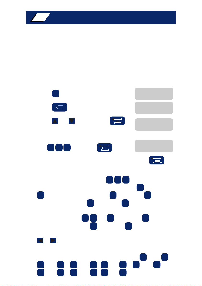
CALL CANCEL MODE
All Nursecall call point transmitters (and other transmitters
requiring attention at the transmitter location) require to be
cancelled at the transmitter following transmission of either a low
priority or high priority call. Pressing the button at the
remote display unit when this type of transmitter is activated a will
tag the message as 'Accepted'. The system will retain the message on
the appropriate queue until the call has been cancelled at the
transmitter.
If a pendant transmitter (or other transmitters not requiring
attention at the transmitter location) is activated, the call will be
displayed at all RDUs. Pressing the button will cancel the
call and remove it from the system. The time and date that the call
was cancelled is printed on the system printer/computer, (if fitted).
SYSTEM OPERATION
4
2

SYSTEM OPERATION (Cont.)
5
MULTIPLE RDUs
Up to seven RDUs can be fitted to a Multiscan System. All RDUs will
normally display the same message, however, in the event of two
users pressing different RDU buttons simultaneously, one of the
RDU displays will display 'SYSTEM BUSY'. In this event retry after 5
seconds. When a user is scanning through a queue of calls, all other
RDUs will be displaying the call at the top of the queue.
FIXED AND PORTABLE RDUs
Remote Display Units can be programmed by the installation
engineer as either fixed or portable units. If an RDU is programmed
as 'Fixed', it must remain plugged into the socket at all times. If
removed the system will initiate a system fault message. If an RDU
is not programmed as 'Fixed', it can be unplugged without causing a
system fault. On some installations spare RDU sockets are fitted at
strategic locations around the site, enabling an RDU to be plugged
into any spare socket, thereby allowing the user to receive all calls
at that location.
Important Note: Ensure that none of the function keys on
'Portable' RDUs are pressed while plugging it into the socket.
EDIT TIMER
In order to avoid the situation where a full function RDU is
inadvertently left in the text editing mode, a timer will automatically
return the system to the normal monitoring mode if more than five
minutes per line of text is taken on any edit option.
SYSTEM PRINTER
If a system printer is connected to the base station and switched
on, it will automatically print the time and date that each call
occurred and the time and date that the call was cancelled. Each
print-out line is accompanied by transmitter description and the
call priority.
2

RADIO PAGING SYSTEM
The Multiscan system can be programmed by the installation
engineer for direct connection to a variety of proprietary radio
paging systems as follows:
SCOPE ALPHA
SCOPE NUM
BLICK
ASCOM 1
ASCOM 2
MULTITONE - NUM
MULTITONE - ALPHA
MULTITONE - LN
All pagers will display the call message in priority order as
described for the RDUs and will cancel calls which have been
cancelled be the Multiscan system, however, the format of the
display and the audible tone will vary for each pager. Refer to pager
manufacturer's operating manual.
RDU/BUTTON CANCEL
RDU/Button cancel allows either the key or external button/
keyswitch to cancel calls and the sounder.
Note: If this mode is not selected, any external button/keyswitches
will silence the sounders but will not cancel any calls.
2SYSTEM OPERATION (Cont.)
6

The system date and time can be changed by the manager using a
full-function RDU as follows:
Changing Date
Action Display Response
1. Press
2. Press
3. Enter new date e.g.,
4. Press
Changing Time
Action Display Response
1. Press
2. Press
3. Enter new time e.g.,
4. Press
CHANGING TIME AND DATE 3
7
F2
280892
1312
F3
x
x
F2 1.13 28 AUG 92
SET TIME
13:12
13:12 12 JUN 91
F3 1.13 12 JUN 91
SET DATE
13 / 06 / 91
1.13 28 AUG 92
SET DATE
28 / 08 / 92
SET TIME
13:12

Each transmitter in the system has two lines of text to describe the
transmitter location. The transmitter text can be changed by the
manager using a full-function RDU as follows. The transmitter text
can also be changed using a personal computer (see page 11)
Action Display Response
1. Press
2. Press
3 . Press or to continue or to
exit editing mode.
4. Enter transmitter number to be edited,
e.g., then press
5. If you do not wish to change the top line text press
and proceed to step 7.
6 . Edit the top line text using the buttons to change
the numeric buttons to letters, e.g., pressing followed by
will enter letter 'A', pressing followed by will enter
letter 'N' and pressing followed by will enter letter 'R'.
Numbers are entered without using the 'F' buttons. Spaces are
entered by pressing or followed by . Full stops
are entered by pressing followed by . To move the
display cursor to a particular character on the display, use the
or buttons.
Example:
To enter MR SMITH on the top line text, press then
then , then , then , then ,
then , then , then
4
8
EDITING TRANSMITTER TEXT
F1
x
QUIT TEXT
ENTER OR SCROLL
ENTER UNIT IDENT
000
TOP LINE
MR JONES
F1 1.13 12 JUN 91
1 5 8
F3F2F1
F1
1F2 5
F3 6
F2F1 F3 0
F3 9
F1 5
F3 69
F3 7F1 5
F1
F3 3F2 7F2 3
Note: If a paging system is fitted, it will be is necessary to read the
section on Pager Displays (page 12). Depending on the type of pager
fitted, the number and type of characters that can be shown by the
pager will vary. When editing the transmitter text, it might be
necessary to modify the text to suit.

Action Display Response
7. Press
8. If you do not wish to change the bottom
line text, press to return to step 3.
9. Enter new bottom line text as previously
described, e.g., WARD G
10. Press to return to step 3
TOP LINE
MR SMITH
BOTTOM LINE
WARD B
BOTTOM LINE
WARD G
QUIT TEXT
ENTER OR SCROLL
9
4
EDITING TRANSMITTER TEXT (cont)
If the system is connected to a printer or IBM personal computer, the
manager can instruct the Multiscan System to transfer all transmitter
text descriptions to the printer or computer. The
following can only be undertaken using a full-function RDU.
Action Display Response
1 . Press or
2. Press
3 . Press or to start the text dump,
or to cancel the request.
Note: Once the text dump has started, it cannot be stopped until
completed. Transmitters with no top line text will be ignored.
PRINTING/DOWNLOADING TEXT
F1 1.13 12 JUN 91
QUIT TEXT DUMP
ENTER OR SCROLL
F2
F1 F3
F1 1.13 12 JUN 91
5

If a transmitter has to be removed from the system, this can be
done by removing the top line text description. The system will
ignore any transmitter which has no top line text or if the top line
text begins with a full stop. (Entering a full stop at the beginning
of a transmitter top line text is a quick method of temporarily
removing a transmitter from the system. The transmitter can be
easily restored by deleting the full stop).
Action Display Response
1. Press
2. Press
3 . Press or
4. Enter transmitter number to be removed,
e.g., then press
5. To remove the top line completely, press
or followed by and hold
down until the text disappears off the
right-hand side of the display. To
temporarily remove the transmitter from
the system, press then .
6. Press
To Restore a Transmitter Temporarily Removed
1. Repeat steps 1 to 3 above
2. Enter transmitter number to be restored,
e.g., then press
3. Press to move cursor to the right
4. Press or followed by to delete
full stop, then press to return to time
and date display.
F1 1.13 12 JUN 91
QUIT TEXT
ENTER OR SCROLL
ENTER UNIT IDENT
000
TOP LINE
MR SMITH
10
REMOVING A TRANSMITTER
6
F1
x
158
F1 F2 F3
F3 9
0
TOP LINE
MR SMITH
13:12 12 JUN 91
ENTER UNIT IDENT
000
TOP LINE
MR SMITH
13:12 12 JUN 91
.
.
158
F1 F2 F3 0
-

11
On large systems, where up to 512 transmitters are installed, the
master processor unit may be connected to a personal computer to
enable uploading of the original transmitter descriptions and for
editing purposes. The format that the text appears on the computer
screen and therefore is transferred to the Multiscan system is
critical and should be as follows:
Transmitter number (000 to 511), comma, followed by the top line
text (0 to 16 characters), comma, followed by bottom line text (0 to
16 characters) followed by carriage return.
E.g., 2,MRS SMITH,WARD H
247,MR JONES,WARD T
7
UPLOADING TEXT FROM A PC
Spaces are permitted in the text character string only. Any line which
is incorrectly formatted is ignored. If a transmitter number has no
text after it, then any existing text against that transmitter on the
Multiscan System is deleted and the transmitter omitted from the
system. Text uploading is initiated from an IBM computer by typing
COPY FILE NAME COM1 followed by <ENTER>. For other computers,
refer to manufacturers instructions.

PAGER DISPLAYS
Depending on the type of pager fitted to the system, the displayed
messages will differ in the number of characters that will be shown
on their LCD displays. All high priority, low priority and cancel calls
are sent to the pagers, while system faults and any other messages
are not paged. Calls of different priority are identified by different
bleep tones by the pager. When a call is paged, the pager is sent two
lines of text which has been programmed against the transmitter,
followed by the bleep tone to identify a high or low priority call.
Depending on the pager type, not all 32 characters of text can be
displayed. The pager will modify the text as necessary. When a call
is cancelled at the RDU (or transmitter, if applicable) a cancel bleep
is emitted from the pager and the call is removed from the display.
Scope Alpha
The Scope format will send all 16 characters the top line of text
intact and the first 14 characters of the bottom line. The Scope
pagers must have a pager code programmed which must be in the
range 0000000-0999999. ( The 7 digits are the pager code with the
first digit being fixed as zero. Only the last 6 digits are actually
entered). Beep tones are identified as: A (cancel), B (low priority)
and D (high priority). All ASCII text can be handled by the pager.
Scope Numeric
The Scope numeric format sends the first 10 characters of the top
line of text only. Any illegal characters are replaced by a space.
Characters which can be sent are: 0123456789U ( ) - , and space.
The pager must have a pager code programmed which must be in the
range 0000000-0999999. ( The last 6 digits are the pager code).
Beep tones are identified as: A (cancel), B (low priority) and D (high
priority).
Blick
The blick format will send all 16 characters of the top line of text,
then all 16 characters of the bottom line of text intact followed by 8
spaces. The total number of characters is 40. Illegal characters will
be replaced by spaces. Characters which can be sent are: A-Z (upper
case only), 0123456789, ( ), + -, SPACE and COMMA. The Blick
pagers must have a pager code programmed in the range 000000-
099999. ( The last 5 digits are the pager code). Beep tones are
identified as: 1 (cancel), 5 (low priority) and 9 (high priority).
Ascom 1
The Ascom Telenova sends only the top line of 16 characters of text.
Only numeric and upper case characters are allowed. Ascom pagers
must have the pager code programmed which must be in the range
000000-000999. ( The last 3 digits are the pager code). Beep tones
are identified as: 1 (cancel), 4 (low priority) and 0 (high priority).
Ascom 2
The Ascom 2 format is the same as the Ascom 1, except that both
top and bottom lines of text are sent (32 characters).
8
12

Multitone Alpha and Multitone LN
The Multitone alphanumeric format sends both top and bottom lines
of text. All ASCII characters are allowed. The pagers must have the
pager code programmed, which must be in the range 000000-009999
(The last 4 digits are the pager code). Beep codes are identified as: 2
(cancel), 4 (low priority) and 5 (high priority).
Multitone NUM
The Multitone Num is identical to the Multitone Alpha, except it
only sends 10 characters limited to the following range of values:
0123456789 space
PAGER DISPLAYS (Cont.) 8
13

SYSTEM FAULT
LOW TX BATTERY
Should an intermittent low tone be emitted from the RDU bleepers, a system fault has
occurred. Where appropriate, the user should take the necessary corrective action.
Transmitter battery low.
Replace battery.
14
SYSTEM FAULT
TX JAMMED ON Faulty transmitter.
Call engineer.
SYSTEM FAULT
CARRIER JAMMING Radio Interference
Call engineer.
SYSTEM FAULT
RDU MISSING
A Remote Display Unit programmed as 'Fixed' has been
removed or is faulty.
Re-fit RDU if unplugged or call engineer if
necessary.
SYSTEM FAULT
RDU ERROR Faulty Remote Display Unit.
Call engineer.
SYSTEM FAULT
MAINS FAIL
Mains supply has failed, the system will continue to run on
stand-by batteries for 20 hours (approx) if the battery is
fully charged.
Check cause of mains failure.
SYSTEM FAULT
LOW 12V BATTERY The system internal battery is low. This will only occur after
mains fail. Reconnect mains if possible.
Communication problem with computer/printer.
Call engineer.
SYSTEM FAULT
RS232 ERROR 1/2
SYSTEM FAULT
PAGER ERROR Check Pager is switched on and operating correctly. Call
engineer if necessary.
SYSTEM FAULT
LID TAMPER The base station lid has been opened.
Call engineer.
SYSTEM FAULT MESSAGES
9
SYSTEM FAULT
BUTTON JAMMED Wiring fault, or RDU fault.
Call engineer.

This page intentionally blank.

This page intentionally blank.

This page intentionally blank.

ScantronicLtd. Perivale IndustrialPark, Greenford,Middx. UB6 7RJ.England
Tel: 081-991 1133, Telex: 915 810 SCANCO G Fax: 081-997 4448
Pt. No. 495709/ NOV / ISSUE 1
SCANTRONIC
Table of contents
Popular Measuring Instrument manuals by other brands

Vertiv
Vertiv GEIST WSCK Quick installation guide

Synrad
Synrad Diode Pointer quick start guide

GE
GE PM880 user manual

Skyla
Skyla HB1 Operator's manual

Bartec Auto ID
Bartec Auto ID Tech500SDE user guide

GEX Corporation
GEX Corporation Thermo Scientific GENESYS 30 Product Specifications and Usage Information