Schaltbau M1 Series User manual

Connect
-
Contact
-
Control
1
Inhalt
Rundsteckverbinder für Spezialanwendungen, Baureihe SB
2
Besondere Merkmale
2
Applikationen
2
Baureihenübersicht
2
Kompetenz
2
Normen
2
Technische Daten
3
Bestellschlüssel
4
5-polig + PE Flanschstecker, Kabeldose
4
6-polig Flanschdose, Kabelstecker
5
14-polig Flanschstecker, Kabeldose
5
Montage
6
Werkzeuge Ausdrückwerkzeuge AWZ-A und AWZ-C/H, Crimpzange CWZ-600
6
Montagebohrungen
6
Kontakte Stecker: Crimpkontakte, Dosen: Lötkontakte
7
Deratingkurven
7
Sicherheitshinweise
7
MSeries
Circular Modular
Connectors
Manual A10-M.en
ConnectorsConnectors

22017-12-21 / V1.3
Connectors Series M – Installation and Maintenance Instructions
Content
1. Important Basic Information......................................................................................... 3
1.1 Legal Notes.............................................................................................................................. 3
1.2 Conventions for this Installation and Maintenance Instructions......................... 3
2. General and Security Information................................................................................ 3
2.1 Observing the Installation and Maintenance Instructions .................................... 3
2.2 User Obligations.................................................................................................................... 3
2.3 Intended Use........................................................................................................................... 4
2.4 Ambient Conditions............................................................................................................. 4
3. Dangers and Security Measures ................................................................................... 5
3.1 Electrical Dangers ................................................................................................................. 5
3.2 Other Hazards......................................................................................................................... 5
3.3 Measures for Avoiding Damages..................................................................................... 6
3.4 Measures for Avoiding Malfunctions............................................................................. 6
4. Description........................................................................................................................ 7
4.1 Features .................................................................................................................................... 7
4.2 Varieties of Conguration .................................................................................................. 7
4.3 Survey of the Components................................................................................................ 8
5. Installation ......................................................................................................................10
5.1 Check Parts for Transport Damage ...............................................................................10
5.2 Assembly of Receptacles/Plugs into a Mounting Wall .........................................10
6. Cable Assembly and Processing .................................................................................12
6.1 Required Tools......................................................................................................................12
6.2 Crimp Contacts (Pin/ Socket) and Filler Plugs ..........................................................13
6.3 Ordering Code for Contacts ............................................................................................14
6.4 Threading Parts on Cables...............................................................................................14
6.5 Make Crimp Connections.................................................................................................16
6.6 Assemble Contacts into Contact Inserts.....................................................................17
6.7 Assemble Filler Plugs .........................................................................................................18
6.8 Assemble Contact Inserts into Receptacle/ Plug shells ........................................18
6.9 Final Assembly of the Connectors.................................................................................20
7. Plugging Procedure.......................................................................................................22
7.1 Plugging.................................................................................................................................22
7.2 Unplugging...........................................................................................................................23
7.3 Attach Protection Caps .....................................................................................................23
8. Regular Visual Checks / Functional Checks ...............................................................25
8.1 Checking Intervals ..............................................................................................................25
8.2 Visual and Functional Check with Every Plugging Procedure ............................25
9. Special Tools and Spare Parts ......................................................................................27
10. Technical Data ................................................................................................................27

3
2017-12-21 / V1.3 Connectors Series M – Installation and Maintenance Instructions
Important Basic Information
1. Important Basic Information
1.1 Legal Notes
Without prior written consent of Schaltbau GmbH, the
installation and maintenance instructions is not al-
lowed to be electronically or mechanically reproduced
– as a whole or in parts – be distributed, changed, trans-
mitted, translated into another language or used in any
other way.
Schaltbau GmbH cannot be held liable for damage
caused by not observing (or only partly observing) the
Installation and maintenance instructions.
1.2 Conventions for this Installation and
Maintenance Instructions
This instructions describe the installation and mainte-
nance of the Mseries connectors.
Cross references are presented in bold italics.
To highlight particularly important safety instructions
and other information, the following symbols are used
in this instructions:
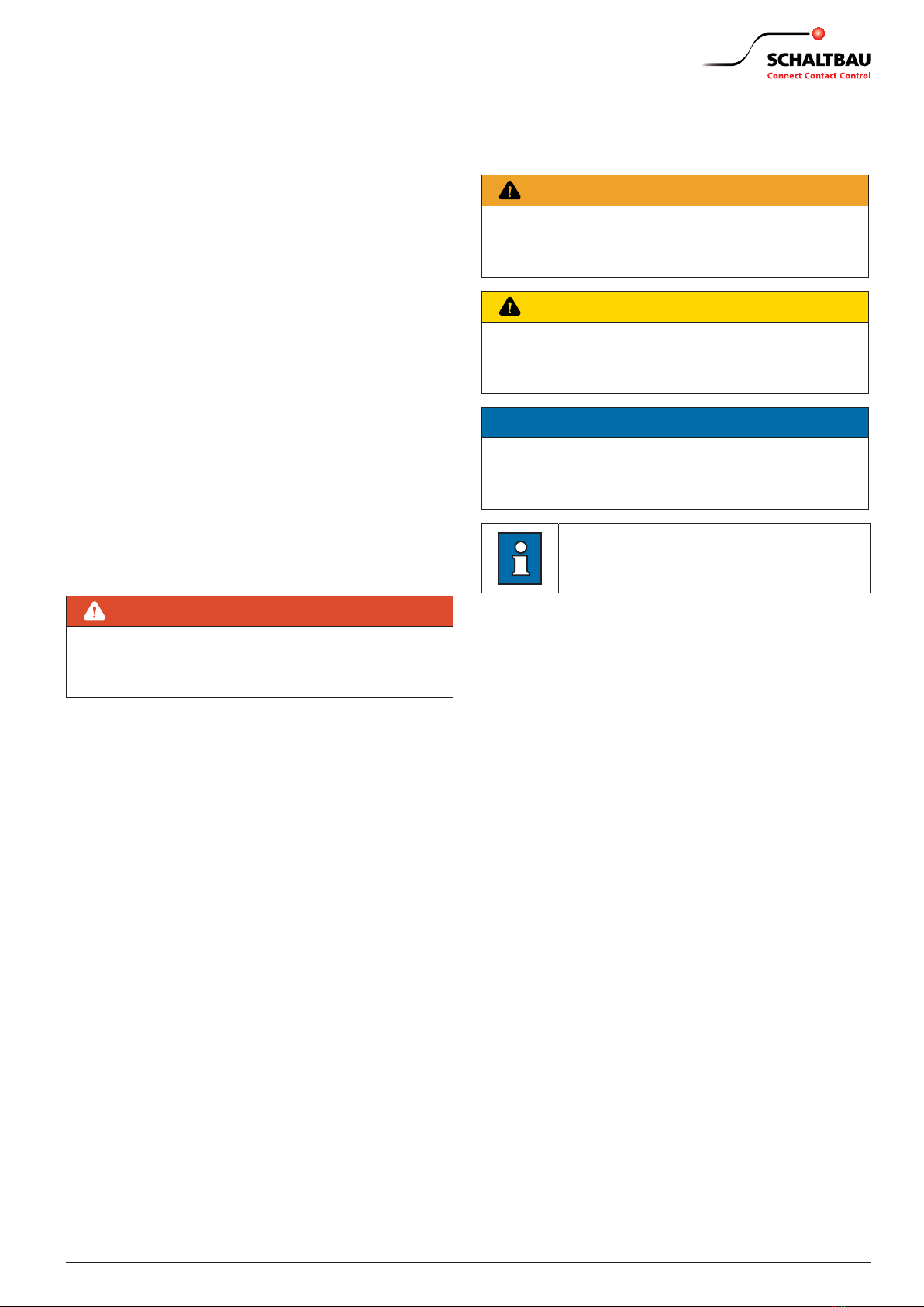
DANGER
Indicates a hazardous situation with a high level of
risk which, if not avoided, will result in death or seri-
ous injury.
WARNING
Indicates a hazardous situation with a medium level
of risk which, if not avoided, could result in death or
serious injury.
CAUTION
Indicates a hazardous situation with a low level of
risk which, if not avoided, may result in minor or
moderate injury.
NOTICE
Indicates a hazardous situation which, if not avoided,
may result in property damage, such as service inter-
ruption or damage to equipment or other materials.
Refers to technical features and methods
aimed at facilitating work or to particu-
larly important information.
2. General and Security Information
The circular industrial connectors dealt with in this doc-
ument are intended for use with low-voltage systems
for special applications. They are designed and tested
in compliance with the generally recognised state of
the art. However, the improper use, operation, handling,
maintenance of or tampering with electric equipment
can cause serious or fatal injury to the user or others, and
the appliance or other property can be damaged.
The operation, maintenance and installation instructions
for the connectors must therefore be strictly followed.
Any uncertainties must be claried and all queries must
include details of the type of device and the serial num-
ber.
Only authorized and trained personnel are allowed to
plan and carry out all mechanical and electrical installa-
tions, transport, commissioning, as well as maintenance
and repair work. This applies to the observation of the
general installation and safety regulations for low-volt-
age systems as well as the proper use of tools approved
for this purpose. Electric equipment requires protection
from moisture and dust during installation and storage.
2.1 Observing the Installation and
Maintenance Instructions
X
All sta must read and understand the instruc-
tions and adhere to them when working with the
device.
X
Always carefully observe all safety warnings!
2.2 User Obligations
X
Observe the respective national instructions and
the other applicable safety regulations for the use
and cable assembly of connectors and connector
systems.
X
Observe all applicable national provisions, all safety,
accident prevention and environmental regulations
as well as the recognized technical rules for safe and
proper working.
X
Carry out regular inspections of all protection and
safety devices to see if they work properly.

42017-12-21 / V1.3
Connectors Series M – Installation and Maintenance Instructions
General and Security Information
X
Work on electric equipment may only be performed
by an expert or trained personnel working under
the direction and supervision of an expert accord-
ing to the applicable rules of electrical engineering.
X
An expert is a person who can judge and recognise
the possible dangers of the jobs commended to
him based on his training, knowledge and experi-
ence and by knowledge of the appropriate regula-
tions.
X
Sta must be informed clearly about who is re-
sponsible for the maintenance of the connectors.
2.3 Intended Use
X
The connectors supply power and signals. They
are intended for plugin and detachable connec-
tions of components, devices and systems only.
X
In order to comply with DIN EN IEC 61984 make
sure that always the live side of the connector – no
matter whether plug or receptacle – is tted with
socket contacts.
X
A symmetrical assembly of the contact insert is
not permitted. Please refer to the chapter „6. Cable
Assembly and Processing“.
X
None of the operating conditions dened in our
catalogue “A10.en” in section “Specications”,
such as voltages, currents, ambient conditions,
etc. may be changed.
X
Work on the connectors must only be carried out
by sta who meets the requirements set out in
these installation and maintenance instructions.
X
According to DIN EN IEC 61984 connectors used
as intended must not be engaged or disengaged
when live or under load.
X
A connector that does not engage easily requires
special attention:
Check for the correct orientation, pollution or if
contacts got bent. Remedy the cause without de-
lay. Never use force! The connector should always
engage easily.
X
In order to meet the requirements of the protec-
tion class and to prevent the connectors against
the entry of dirt or moisture, make sure that plugs
and receptacles, when not mated, are always
closed with protection caps.
X
When disengaging a connector, pull the plug and
never the cable.
X
Use the connector only according to its intended
use. Replace or repair damaged parts exclusively
with original parts. Any other usage of or tamper-
ing with the connector is considered contrary to its
intended use. No liability is assumed for damages
and accidents caused due to non-compliance with
the instructions or improper use of the connector.
2.4 Ambient Conditions
NOTICE
The connectors are constructed for specic ambient
conditions.
X
Operate the connectors only under the ambi-
ent conditions, like temperature ranges and IP
protection classes as dened in our catalogue
A10.en in section “Specications“ (schaltbau.
info/download1en).
Note:
In case of a very low or very high ambient temperature
which approximates the limits of the allowable oper-
ating temperature range specied in our catalogue
A10.en in section “Specications”,
-a higher eort may be needed for the plugging and
unplugging and
-the operational life span of plug and coupling recep-
tacle may thus be reduced due to increased wear and
tear.

5
2017-12-21 / V1.3 Connectors Series M – Installation and Maintenance Instructions
Dangers and Security Measures
3. Dangers and Security Measures
3.1 Electrical Dangers
DANGER
The connectors contain components that carry voltage. Deadly hazard!
Always observe the following safety regulations before beginning any work on electrical
constructions:
X
Disconnect
X
Ensure that it is not possible to reconnect unintentionally
X
Clearly mark your work area
X
Make sure that there is no voltage present
X
Earth and short circuit the installation
X
Insulate or cover adjacent energized parts
X
Only an electrically skilled person may determine if there is no voltage present
WARNING
A wrong pin conguration of the contact inserts may cause a deathly electric shock.
X
Make sure that associated pin contacts and socket contacts are always inserted in the corre-
sponding contact cavities with identical pin conguration!
X
Make sure that contacts with phase assignment are not mounted into contact cavities which
are destined for the protective earthing (PE) contact!
X
Refer to chapter „6. Cable Assembly and Processing“.
3.2 Other Hazards
WARNING
Exclusively use the connectors for purposes as indicated in the specications and data sheets.
A wrong application can cause accidents and severe damages to persons.
X
The manufacturer doesn‘t take the responsibility for accidents which were caused by improper
use of the product.
X
We recommend the use of fault current safety systems in constructions with voltages higher
than safety extra-low voltage.
WARNING
The plugging and disconnecting of the connectors on-load can cause electric arcs. When explosive
substances or ignition sources of any kind are nearby, there is a risk of re and explosion!
X
Never plug and disconnect the connectors on-load.

62017-12-21 / V1.3
Connectors Series M – Installation and Maintenance Instructions
Dangers and Security Measures
3.3 Measures for Avoiding Damages
NOTICE
Improper handling of the connector, e.g. when hitting the oor with some impact, can result in breakage, visible
cracks and deformation.
X
Make sure that the connectors are handled appropriately.
X
Carry out regular visual checks to detect possible damages.
X
Replace damaged parts immediately.
3.4 Measures for Avoiding Malfunctions
NOTICE
In the case of damage, wear and tear and/or soiling of the connector components - in the form of a partial break,
sharp edges and discoloured surfaces - the functional safety of the connectors is no longer guaranteed.
X
Carry out regular visual checks to detect wear and tear and dirt.
X
Immediately replace damaged parts.
X
Immediately remove dirt without leaving any residues.
X
Immediately replace parts with stubborn dirt.
NOTICE
Inappropriate handling when plugging or disconnecting may damage the connectors. The functional safety of
the connectors is no longer guaranteed when parts are damaged.
X
Make sure that the guideways and slots of plug and receptacle always interlock when plugging!
X
Take care that plug and receptacle do not tilt and that they are plugged without force.
X
Make sure before the plugging procedure that plug and receptacle as well as the protection caps are not
soiled. Remove existent dirt without leaving any residues.
X
Make sure that in the not mated condition the protection caps are always attached according to regulations.

7
2017-12-21 / V1.3 Connectors Series M – Installation and Maintenance Instructions
Description
4. Description
Connectors of the M series are universal industry con-
nectors and oer high reliability.
M1 and M3 connectors are dust-proof and water pres-
sure tight (protection class IP67 when mated and IP69K
when not mated with screwed on protection cap).
Moreover, they are largely resistant to acids and alka-
lines as well as to heat and cold.
There is a large application range. Typical applications
are systems and components where reliability under
dicult circumstances is important, e.g. in mining,
shipbuilding, power plant construction, mechanical
and trac engineering, environmental technology or
in food processing.
Connectors of the M series have a modular design
which oers a wide range of applications.
4.1 Features
Common features of M1 and M3 series connectors:
X
Modular design: Customized and cost-eective
realisation of your application.
X
Shells: Various kinds of assembly, e.g. plug and re-
ceptacle shells with and without strain relief, with
ange, for use with heat shrink boots or backshells
with thread and cable gland, also ange-mount
angled receptacle. Materials used:
-Fibre glass reinforced polyamide: impact resist-
ant
-Non-halogen, UL listed
X
Design exibility: Plug and receptacle shell can
be tted with either pin or socket insert, i.e. fully
insulated socket inserts can be mounted on the
live part.
X
Orientation: Pin and socket inserts can be located
in the shell in two dierent positions, thus pre-
venting mismating. It also allows for the unmistak-
able connection of for example two connectors
with dierent voltages to one and the same piece
of equipment.
X
Contacts:
-High-quality screw machine contacts
-Silver or gold plated
-Crimp connection depending on series and
contact arrangement from 0.5 … 6 mm².
Special features of M1 series:
X
Number of contacts: 4 and 6 + PE
X
5.000 mating cycles at constant low contact resist-
ance
X
Current rating:16 A max
Special features of M3 series:
X
Number of contacts: 6 + PE, 5+3 + PE, 12 +PE and
7+7 + PE
X
5.000 mating cycles at constant low contact resist-
ance
X
Current rating: 50 A max
4.2 Varieties of Conguration
On the next pages you can nd a survey of the exten-
sive varieties of conguration of the dierent connec-
tor components for the M1 and M3 series. The survey
shows how the components listed below may be com-
bined with each other:
X
Plug shells
X
Receptacle shells
X
Inserts and types of contacts
X
Cable sleeves, shrink boots
X
Backshells
X
Cable glands
X
Protection caps
Under the following link on our homepage you can
moreover nd a congurator with the help of which
you can assemble the various connector components
in a comfortable way:
www.schaltbau-gmbh.com/en/Products/Connectors/M-
series/
In order to nd the congurator, click on the symbol
with the two gears under the desired series on our
homepage:

82017-12-21 / V1.3
Connectors Series M – Installation and Maintenance Instructions
Description
4.3 Survey of the Components
Pg
M
Pg
Pg
Pg
M
Pg
Overview: M1 Plug
Protection capInsertContactShell part 1Shell part 2Cable gland
M1 KS
Protection cap with cord
for plugs
M1 K
Protection cap with plastic strap
for plugs
M16 Z / M16 ZB
Cable plug with backshell,
strain relief and cable gland
M16
Cable plug with backshell
and cable gland
M16 W
Threaded plug for use with
backshell/shrink boot
M15
Flange plug
202K142-15
Shrink boot, straight
T1-x
Cable sleeve
222K142-15
Shrink boot, 90°
M1 E-4P+PE
Pin insert
M1 E-4S+PE
Socket insert
M1 E-6P+PE
Pin insert
M1 E-6S + PE
Socket insert
SAC-x.xx-yy
Pin contact
BAC-x.xx-yy
Socket contact
BS-A-V10
Filler plug
M1 M20
Backshell M20x1,5
M1 VM208-13
Cable gland M20x1,5
M1 Pg13,5
Backshell Pg13,5
M1 Pg13,510-12
Cable gland Pg13,5
Protection capInsertContactShell part 1Shell part 2Cable gland
Pg
Pg
MM
Pg
Pg
Pg
Pg
Pg
Pg
Overview : M3 Plug
M3 E-6P+PE
Pin insert
M3 E-6S+PE
Socket insert
M3 E-5P+3P+PE
Pin insert
M3 E-5S+3S+PE
Socket insert
SAC-x.xx-yy
SBC-x.xx-yy
SCC-x.xx-yy
Pin contact
BAC-x.xx-yy
BBC-x.xx-yy
BCC-x.xx-yy
Socket contact
BS-A-V10
BS-B-V10
BS-C-V10
Filler plug
M36 Z / M336ZB
Cable plug wih backshell,
strain relief and cable gland
M35
Flange plug
M36W
Threaded plug for use with
backshell/shrink boot
M3 E-12P+PE
Pin insert
M3 E-7P+7P+PE
Pin insert
M3 E-12S+PE
Socket insert
M3 E-7S+7S+PE
Socket insert
202K163-15
Shrink boot, straight
T28-x
Cable sleeve
222K142-15
Shrink boot, 90°
M3M25
Backshell M25x1.5
M3VM2511-17
Cable gland M25x1.5
M3VPg1612-14
Cable gland Pg16
M3VPg2114-18
Cable gland Pg21
M3Pg16
Backshell Pg16
M3Pg21
Backshell Pg21
M3KS
Protection cap with cord
for plugs
M3K
Protection cap with plastic strap
for plugs

9
2017-12-21 / V1.3 Connectors Series M – Installation and Maintenance Instructions
Description
M
Pg
PgPg
MM
Pg
M
Overview: M1 Receptacle
Protection capInsert Contact Shell part 1Shell part 2Cable gland
M11 Z / M11 ZB
Cable receptacle with backshell
strain relief and cable gland
M11
Cable receptacle with backshell
and cable gland
M14Pg13,5
Pg13,5 threaded receptacle
M14M20
M20x1,5 threaded receptacle
M13
Flange mount receptacle
M18
Flange mount angled receptacle
M1 DS
Protection cap with cord
for receptacles
M1 D
M1 E-4P+PE
Pin insert
M1 E-4S+PE
Socket insert
M1 E-6P+PE
Pin insert
M1 E-6S + PE
Socket insert
T1-x
Cable sleeves
SAC-x.xx-yy
Pin contact
BAC-x.xx-yy
Socket contact
BS-A-V10
Filler plug
M1 M20D
Backshell M20x1,5 M1 VM208-13
Cable gland M20x1,5
M1 Pg13,5
Backshell Pg13,5 M1 Pg13,510-12
Cable gland Pg13,5
Protection cap with plastic strap
for receptacles
Protection cap Insert Contact Shell part 1Shell part 2Cable gland
Pg
Pg
M
Pg
PgPg
PgPg
M
Pg
M
Overview
:
M3 Receptacle
M3 E-6P+PE
Pin insert
M3 E-6S+PE
Socket insert
M3 E-5P+3P+PE
Pin insert
M3 E-5S+3S+PE
Socket insert
SAC-x.xx-yy
SBC-x.xx-yy
SCC-x.xx-yy
Pin contact
BAC-x.xx-yy
BBC-x.xx-yy
BCC-x.xx-yy
Socket contact
BS-A-V10
BS-B-V10
BS-C-V10
Filler plug
M3 E-12P+PE
Pin insert
M3 E-7P+7P+PE
Pin insert
M3 E-12S+PE
Socket insert
M3 E-7S+7S+PE
Socket insert
M31Z / M31ZB
Cable receptacle with backshell,
strain relief and cable gland
M33 W
Receptacle for use with
shrink boot
M38
Flange mount angled receptacle
M33
Flange mount receptacle
M34Pg21
Pg21 threaded receptacle
M34M30
M30x1,5 threaded receptacle
M3M25D
Backshell M25x1,5 M3VM2511-17
Cable gland M25x1,5
M3VPg1612-14
Cable gland Pg16
M3VPg2114-18
Cable gland Pg21
M3Pg16
Backshell Pg16
M3Pg21
Backshell Pg21
M3DS
M3D
202K163-15
Shrink boot, straight
T28-x
Cable sleeve
222K142-15
Shrink boot, 90°
Protection cap with cord
for receptacles
Protecttion cap with plastic strap
for receptacles

10 2017-12-21 / V1.3
Connectors Series M – Installation and Maintenance Instructions
Installation
5. Installation
DANGER
The connectors contain components that carry voltage. Deadly hazard!
Always observe the following safety regulations before beginning any work on electrical
constructions:
X
Disconnect
X
Ensure that it is not possible to reconnect unintentionally
X
Clearly mark your work area
X
Make sure that there is no voltage present
X
Earth and short circuit the installation
X
Insulate or cover adjacent energized parts
X
Only an electrically skilled person may determine if there is no voltage present
NOTICE
During installation, ensure that dirt caused by sur-
rounding construction activities does not get into
the connectors.
5.1 Check Parts for Transport Damage
NOTICE
The functional safety of the connectors is no longer
guaranteed when parts are damaged.
X
Before installing, check all parts for any possible
transport damage.
X
Do not install any damaged parts.
5.2 Assembly of Receptacles/ Plugs into
a Mounting Wall
Preparing measures
Appropriate mounting holes have to be prepared de-
pending on the model for the mounting of receptacles
and plugs with ange or thread into a mounting wall
(refer to section „Mounting holes / thread“).
In order to relieve the contacts from strain when assem-
bled, a strain relief has to be provided on the mounting
wall.
Fastening of receptacles / plugs with ange
For the fastening of receptacles and plugs with ange
you need screws according to the following table:
Series Model of receptacle / plug Size of screw
(number)
M1 Receptacle/plug with ange M3 (2x)
Angle receptacle with ange M3 (4x)
M3 Receptacle/plug with ange and
angle receptacle with ange
M4 (4x)
The length of the fastening screws as well as appropri-
ate thread locker elements have to be determined ac-
cording to the assembly situation.
The torque has to be determined according to the
screws used and to the materials existing on the site of
the assembly.
Fastening of receptacles / plugs with thread
For the fastening of receptacles with thread, corre-
sponding threads have to be prepared in the mounting
wall.
Torque for all receptacles with thread: 2.5 Nm.
Dimensions
The measures for the dierent receptacles and plugs
with ange or thread may be taken from the following
table:

11
2017-12-21 / V1.3 Connectors Series M – Installation and Maintenance Instructions
Installation
Model of receptacle / plug
(diagrams not true to scale)
Dimensions [mm]
Series M1 Series M3
Flange mount receptacles
M1, M3 M1 M3
x
a
bØ d
Ø c
f
h
e
Ø
g
m
Ø
n
k
j
M13
a = 27
b = 18
c = Ø 20,4
d = Ø 30
e = Tr26x2
f = 41
g = Ø 3,2
h = 34
x = Immersion depth13,5
M33
a = 31,5
b = 22,7
c = Ø 29
j = Tr38x6 P3
k = o32,5
m = o42
n = Ø 4,3
x = Immersion depth 15
Flange mount angled receptacles
M1, M3
cf
a
e max.
h max.
g
b
Ø
d
M18
a = Tr26x2
b = o30,5
c = o38,5
d = Ø 3,4
e = 65 max.
f = 35,5
g = 58
h = 115 max
M38
a = Tr38x6 P3
b = o43,5
c = o51,5
d = Ø 4,3
e = 95 max.
f = 53,5
g = 87
h = 150 max
Flange mount plugs
M1, M3 M1 M3
Ø
n
k
p
j
Ø
m
e
Ø d
f
g
ba
Ø
c
Ø
h
M15
a = 37,5
b = 28,5
c = Ø 20,4
d = Ø 31
e = Tr26x2
f = 34
g = 41
h = Ø 3,2
M35
a = 43,5
b = 34,5
c = Ø 29
j = Tr38x6 P3
k = o32,5
m = o42
n = Ø 4,3
p = Ø 45
Receptacles with thread
M1, M3
x
b
aØ e
f
c
d
g
M14
a = 31,5
b = 22,5
c/d = Pg13,5/M20x1,5
e = Ø 30
f = Tr26x2
g = SW 27
x = Immersion depth 13,5
M34
a = 31,5
b = 22,7
c/d = Pg21/M30x1,5
e = Ø 40
f = Tr38x6 P3
g = SW 38
x = Immersion depth 15
Plugs with thread
M1, M3
Ø
e
d
g
b
Ø
c
a
fh
j
M16W
a = 35,8
b = 3,5
c = Ø 19
d = Pg 13,5
e = Ø 21,4
f = 1
g = 12,5
h = Tr26x2
j = Ø 31
M36W
a = 46,5
b = 3,5
c = Ø 27
d = Pg 21
e = Ø 29
f = 5,5
g = 26,5
h = Tr38x6 P3
j = Ø 45

12 2017-12-21 / V1.3
Connectors Series M – Installation and Maintenance Instructions
Cable Assembly and Processing
Mounting holes / thread
You may take the measures for the mounting holes for
the assembly of the dierent receptacles and plugs
with ange or thread into a mounting wall from the fol-
lowing diagram.
Flange mount receptacles and plugs Flange mount angled receptacles Receptacles with thread
34
Ø 21
Ø 3.2Ø 4.3
□ 32.5
Ø 29.5
□ 30.5
Ø 27
Ø 3.2
□ 43.5
Ø 37
Ø 4.3
Pg13.5
M20x1.5Pg21
M30x1.5
M13, M15 M33, M33 W, M35 M18 M38 M14 M34
Fig. 1: Dimensions and arrangements of the mounting holes and threads (measures in mm)
6. Cable Assembly and Processing
6.1 Required Tools
X
Insertion tools for socket inserts
Fig. 2: Insertion tools for socket inserts
Ordering code Insertion tools for
VW-M1 E-4S Contact insert M1 E-4S+PE
VW-M1 E-6S Contact insert M1 E-6S+PE
VW-M3 E-6S Contact insert M3 E-6S+PE
VW-M3 E-5S+3S Contact insert M3 E-5S+3S+PE
VW-M3 E-12S Contact insert M3 E-12S+PE, M3 7+7S+PE
X
Insertion tools for pin inserts
Fig. 3: Insertion tools for pin inserts
Ordering code Insertion tools for
VW-M1 E-4P Contact insert M1 E-4P+PE
VW-M1 E-6P Contact insert M1 E-6P+PE
VW-M3 E-6P Contact insert M3 E-6P+PE
VW-M3 E-5P+3P Contact insert M3 E-5P+3P+PE
VW-M3 E-12P Contact insert M3 E-12P+PE, M3 7+7P+PE
X
Extraction tools for disassembly of contacts
Fig. 4: Extraction tool
Ordering code Extraction tools for
AWZ-A Contacts type SAC-x
AWZ-B Contacts type SBC-x, BBC-x
AWZ-C/H Contact type SCC-x, BCC-x
X
Crimping pliers
Fig. 5: Crimping pliers
Ordering code Crimping pliers for
CWZ-600-1 SAC-x, BAC-x, SBC-x, BBC-x, SCC-x and BCC-x, (not ap-
propriate for contacts SAC-2.50-xx and BAC-2.50-xx)
Tool frame M22520/1-01
and Turret M22520/1-02
(without illustration)
For contacts SAC-2.50-xx and BAC-2.50-xx only.
Crimping pliers and turret from the company DMC
or the company Buchanan. Order directly from the
manufacturer.
X
Wire stripping tools, commercially available
X
Tweezers, commercially available (for inserting ller plugs)

13
2017-12-21 / V1.3 Connectors Series M – Installation and Maintenance Instructions
Cable Assembly and Processing
6.2 Crimp Contacts (Pin / Socket) and Filler Plugs
Contact type Contact model L1 L2 Identier Ordering code 1) Connection
cross-section
Pin contact SAC-x
Ø 1.58 mm
Connection
cross-section
IdentifierØ1.58
L1
Ø3.76
28.6 -
without groove
1 groove
2 grooves
3 grooves
SAC-0.50-Ag
SAC-1.00-Ag
SAC-1.50-Ag
SAC-2,50-Ag
0.5 mm2
0.75 ... 1 mm2
1.5 mm2
2.5 mm2
Socket contact BAC-x
Ø 1.58 mm
Connection
cross-section
Identifier
L2
Ø1.58 Ø3.76
- 28.6
without groove
1 groove
2 grooves
3 grooves
BAC-0.50-Ag
BAC-1.00-Ag
BAC-1.50-Ag
BAC-2.50-Ag
0.5 mm2
0.75 ... 1 mm2
1.5 mm2
2.5 mm2
Filler plug 2)
BS-A-V10
19.5
- - - BS-A-V10 -
Pin contact SBC-x
Ø 2.3 mm
Connection
cross-section
Identifier
L1
Ø2.3Ø5.15
40.4
40.4
40.4
39.0
39.0
39.0
-
without groove
1 groove
2 grooves
3 grooves
1 broad groove
2 broad
grooves
SBC-0.50-Ag
SBC-1.00-Ag
SBC-1.50-Ag
SBC-2.50-Ag
SBC-4.00-Ag
SBC-6.00-Ag
0.5 mm2
1.0 mm2
1.5 mm2
2.5 mm2
4.0 mm2
6.0 mm2
Socket contact BBC-x
Ø 2.3 mm
Connection
cross-section
Identifier
L2
Ø2.3Ø5.15
-
37.0
37.0
37.0
35.6
35.6
35.6
without groove
1 groove
2 grooves
3 grooves
1 broad groove
2 broad
grooves
BBC-0.50-Ag
BBC-1.00-Ag
BBC-1.50-Ag
BBC-2.50-Ag
BBC-4.00-Ag
BBC-6.00-Ag
0.5 mm2
1.0 mm2
1.5 mm2
2.5 mm2
4.0 mm2
6.0 mm2
Filler plug 2)
BS-B-V10
31
- - - BS-B-V10 -
Pin contact SCC-x
Ø 4.0 mm
Connection
cross-section
Identifier
L1
Ø4.0Ø7.2
37.5
37.5
37.5 -
3 grooves
1 broad groove
2 broad
grooves
SCC-2.50-Ag
SCC-4.00-Ag
SCC-6.00-Ag
2.5 mm2
4.0 mm2
6.0 mm2
Socket contact BCC-x
Ø 4.0 mm
Connection
cross-section
Identifier
L2
Ø4.0 Ø7.2
-
32.6
32.6
32.6
3 grooves
1 broad groove
2 broad
grooves
BCC-2.50-Ag
BCC-4.00-Ag
BCC-6.00-Ag
2.5 mm2
4.0 mm2
6.0 mm2
Filler plug 2)
BS-C-V10
31.5
- - - BS-C-V10 -
1) The standard contact surface for pin and socket contacts is silver (AG). For gold plated contacts (AU) please change the
contact surface from“AG”to “AU”in the ordering code.
2) Filler plugs serve as an equipment of not congurated contact cavities in the contact inserts:
-For socket inserts: A whole ller plug is inserted into every not congurated contact cavity.
-For pin inserts: A whole ller plug is cutted in the middle and only half a ller plug is inserted into every not congurated
contact cavity.

14 2017-12-21 / V1.3
Connectors Series M – Installation and Maintenance Instructions
Cable Assembly and Processing
6.3 Ordering Code for Contacts
Example: SAC-1.00-AG
Contact type
S Pin contact
B Socket contact
Contact surface
AG Silver
AU Gold
Contact diameter
A 1.58 mm
Connection cross
section
B 2.30 mm 0.5 mm2
C 4.00 mm 0.75 ...1,00 mm2
1.50 mm2
Terminal Type 2.50 mm2
C Crimp 4.00 mm2
6.00 mm2
6.4 Threading Parts on Cables
The following illustrations show for some examples how the connector parts have to be threaded on the cables.
Plugs / receptacles for cables
Depending on the application, at rst thread all parts (1 to 6) on the cable.
124
3
Fig. 6: Example for plug with back shell, strain relief and cable gland (applies also for cable receptacles)
1 Back shell with strain relief and cable gland
2 Cable sleeve with pre-assembled pressure disc
3 Protection cap for plugs or receptacles respectively
4 Plug or receptacle shell respectively
1 52 6
4
3
Fig. 7: Example for plug with thread, back shell and cable gland (applies also for receptacles with thread)
1 Cable gland
2 Strain relief with rubber ring
3 Protection cap for plugs or receptacles respectively
4 Back shell
5 O-ring
6 Plug or receptacle shell respectively

15
2017-12-21 / V1.3 Connectors Series M – Installation and Maintenance Instructions
Cable Assembly and Processing
23
1
Fig. 8: Example for plug with threaded rear skirt and 90°
shrink boot (applies also for receptacles with thread)
1 Shrink boot 90°
2 Protection cap for plugs or receptacles respectively
3 Plug or receptacle shell respectively
Protection caps for cable receptacles and cable plugs
The following table shows, how protection caps with cords or plastic clips have to be threaded properly on the dif-
ferent cable receptacles and cable plugs.
Protection caps for cable receptacles Protection caps for cable plugs
M1 series
M14 with cord M14 with plastic clip M16 with cord M16 with plastic clip
M11 with cord M11 with plastic clip M16 W with back shell
with cord
M16 W with back shell
with plastic clip
M3 series
M31 mit Schnur M31 with plastic clip M36 with cord M36 with plastic clip
M34 with cord M34 with plastic clip M36 W with back shell
with cord
M36 W with back shell
with plastic clip

16 2017-12-21 / V1.3
Connectors Series M – Installation and Maintenance Instructions
Cable Assembly and Processing
Plugs / receptacles with ange for wall
assembly
X
Slide the cable from the rear through the mount-
ing wall (8).
X
Thread the plug / receptacle with ange (9) on the
cable and mount the ange with the fastening
screws on the mounting wall (8) with the prepared
mounting hole.
X
In doing so, also screw on protection cap (10) with
one of the fastening screws on the ange (11).
X
For the assembly use
-M3 screws for M1 series,
-M4 screws for M3 series.
The torque for the fastening screws is in both series
2.5Nm.
M1 K15
M3 K35
9
10
8
11
Fig. 9: Example of assembly for ange mount plugs on a
mounting wall (applies also for receptacles with
ange)
Plugs / receptacles with thread for wall
assembly
NOTICE
Loctite 5331 threadlocker is to be used for the plugs/
receptacles with thread for wall assembly.
X
Slide the cable from the rear through the mount-
ing wall (12).
X
Thread the protection cap (14) on the thread side
onto the plug/receptacle (13).
X
Thread the plug/receptacle with thread (13) onto
the cable.
X
Apply Loctite 5331 to the thread (15) and screw
the plug/receptacle into the mounting wall fur-
nished with the same thread.
The torque for all receptacles with thread is 2.5 Nm.
For the assembly of the contacts and contact inserts
refer to section „6.6 Assemble Contacts into Contact
Inserts“ und „6.8 Assemble Contact Inserts into Recep-
tacle / Plug shells“.
13
14
12
15
Fig. 10: Example of assembly for receptacles with thread on a
mounting wall (applies also for plugs with thread)
6.5 Make Crimp Connections
The connection of the crimp contacts has to be made
according to DIN EN 60352-2 – Solderless Connections.
In order to comply with DIN EN IEC 61984 make sure that
always the live side of the connector – no matter wheth-
er plug or receptacle – is tted with socket contacts.
For all contact inserts observe the following:
-for pin inserts a socket contact must be used for the
protective earthing (PE) contact,
-for socket inserts a pin contact must be used for the
protective earthing (PE) contact.
Assembly
X
Disengage the cable at the connection end from
the coating and strip cable strands approx. 7 mm.
X
Push the cable strands into the contacts.
X
Crimp the cable strands to the contacts using the
crimping pliers.
-In doing so, observe connection cross-section
of contacts depending on the model of the
crimp contacts (refer to section “6.2 Crimp con-
tacts (pin / socket) and ller plugs”).
-Crimping must be made in the centre between
the sight drill hole and the end of the contact.
7 mm
Fig. 11: Skin cable strands and crimp to contacts.

17
2017-12-21 / V1.3 Connectors Series M – Installation and Maintenance Instructions
Cable Assembly and Processing
Check
X
Check if crimp contacts are rmly and correctly
connected.
-Make sure that no single wires stick out.
Check extraction forces according to DIN EN
61238-1.
6.6 Assemble Contacts into Contact
Inserts
After all the cable strands have been crimped with the
contacts and have been checked for rm and correct
connection, the contacts may be assembled into the
contact inserts.
WARNING
A wrong pin conguration of the con-
tact inserts may cause a deathly electric
shock.
X
Make sure that associated pin and
socket contacts are always inserted
into the corresponding contact cavi-
ties with identical pin conguration!
X
Make sure that contacts with phase
assignment are not mounted into
contact cavities which are destined
for the protective earthing (PE)!
Assembly
X
Inserting of the contacts (1) into the contact insert
(2) is made starting from the middle outwards: In
doing so, push every single contact to limit stop
into the contact insert until the contact locks au-
dibly.
X
Insert ller plugs from the plug side into the con-
tact insert of not congurated contact cavities, re-
fer to section „6.7 Assemble Filler Plugs“.
1
2
Fig. 12: Pushing contacts (1) into contact inserts (2)
Check
X
Check if all contacts are rmly in place: test force
40 N.
Disassembly
X
In order to remove contacts from the contact in-
serts, adequate extraction tools are needed, refer
to section „6.1 Required Tools“.
X
Attach the extraction tool (3) to the contact (4) and
extract the contact from the contact insert.
NOTICE
After a contact has been extracted, the interlock
function of the plastic clip (5) is no longer guaran-
teed. When the contact is reused, a new plastic clip
– tting for the type of contact – must be used! (Refer
to chapter „9. Special Tools and Spare Parts“)
3
4
5
Fig. 13: Disassembling of contacts (4) with extraction tool (3).
When using the contact again a new plastic clip (5) is
absolutely necessary.

18 2017-12-21 / V1.3
Connectors Series M – Installation and Maintenance Instructions
Cable Assembly and Processing
6.7 Assemble Filler Plugs
Filler plugs have to be inserted into not congurated
contact cavities of the contact inserts. Depending on
the contact insert, ller plugs of dierent models and
with corresponding diameters are available, refer to
section „6.2 Crimp Contacts (Pin / Socket) and Filler
Plugs“.
The following illustrations show for dierent examples
of application how ller plugs have to be assembled
into the contact inserts.
X
Use tweezers (2) for easier insert of small ller
plugs (1).
1
2
Fig. 14: Insert of small ller plugs (1) (e. g. BS-A/BS-B) with
tweezers (2)
For socket inserts:
X
Insert one whole ller plug (1/3) per not congu-
rated contact cavity.
3
Fig. 15: Assembly of whole ller plugs (3) for socket inserts
For pin inserts:
X
Cut through one whole ller plug in the middle
and only insert half a ller plug (4) per not congu-
rated contact cavity.
4
Fig. 16: Assembly of half ller plugs (4) for pin inserts
X
Insert the ller plug from the plug side into the
contact insert and push until the end stop.
5
Fig. 17: Final position (5) of the assembled ller plug
6.8 Assemble Contact Inserts into
Receptacle / Plug shells
After all the contacts have been made and the contacts
and the ller plugs, if necessary, have been assembled
into the contact insert, the contact insert must be in-
serted into the shell and locked with the help of ad-
equate insertion tools (refer to section „6.1 Required
Tools“).
Codings
The receptacle and plug shells as well as the corre-
sponding contact inserts are equipped with codings in
the form of grooves and guideways.
M1 M3
Fig. 18: Examples for codings: Grooves on the contact inserts,
guideways on the inner sides of the shells
All contact inserts have 2 coding posi-
tions (A, B). This allows for the unmis-
takable connection of for example two
connectors with dierent voltages to one
and the same piece of equipment.

19
2017-12-21 / V1.3 Connectors Series M – Installation and Maintenance Instructions
Cable Assembly and Processing
In the following table, the coding positions A and B are
illustrated for the dierent contact inserts. The illustra-
tions refer respectively to the mounting position of the
corresponding contact insert.
During assembly, the contact inserts must be pressed
downwards in an axial direction into the housing with
the tting insertion tool up to the detectable mechani-
cal stop. (This equates to overriding the corrugated
spring up to the mechanical stop.)
In this pressed position, turn the contact insert in a
clockwise direction to the nal position.
The insertion tool must be brought out in this position.
The contact insert is then pushed up by the corrugated
spring up to the stop.
Coding position A Coding position B
(rotated by 90° from coding position A)
Pin inserts Socket inserts Pin inserts Socket inserts
Series M1
AB
1
2
3
4
PE
45°
Mounting
position
Final position
M1 E-4P+PE
1
23
4
PE
45°
Mounting
position
Final position
A
B
M1 E-4S+PE
A
B
1
2
3
4
PE
45°
Mounting
position
Final position
M1 E-4P+PE
45°
Mounting
position
Final position
1
23
4
PE A
B
M1 E-4S+PE
1
562
3
4
PE
45°
Mounting
position
Final position
A
B
M1 E-6P+PE
15
6
234
PE
45°
Mounting
position
Final position
A
B
M1 E-6S+PE
1
562
3
4
PE
45°
Mounting
position
Final position
A
B
M1 E-6P+PE
45°
Mounting
position
Final position
15
6
234
PEA
B
M1 E-6S+PE
Series M3
2
3
15
64
PE
45°
Mounting
position
Final position
A
B
M3 E-6P+PE
2
3
1
56
4
PE
45°
Mounting
position
Final position
A
B
M3 E-6S+PE
2
3
15
64
PE
45°
Mounting
position
Final position
A
B
M3 E-6P+PE
45°
Mounting
position
Final position
2
3
1
56
4
PE
A
B
M3 E-6S+PE
45°
Mounting
position
Final position
1
2
6
7
854
PE
3
M3 E-5P+3P+PE 1)
45°
Mounting
position
Final position
12
678
5
4
PE 3
M3 E-5S+3S+PE 1)
45°
Mounting
position
Final position
1
2
6
7
854
PE
3
M3 E-5P+3P+PE 1)
45°
Mounting
position
Final position
12
678
5
4
PE 3
M3 E-5S+3S+PE 1)
1
56
47
10
11 12
92
3 8
PE
45°
Mounting
position
Final position
A
B
M3 E-12P+PE
1
5
64
7
10
1112
923
8
PE
45°
Mounting
position
Final position
A
B
M3 E-12S+PE
1
56
47
10
11 12
92
3 8
PE
45°
Mounting
position
Final position
A
B
M3 E-12P+PE
45°
Mounting
position
Final position
1
5
64
7
10
1112
923
8
PE
A
B
M3 E-12S+PE
1
5 6
47
10
11
14 12
13
9
2
38
PE
45°
Mounting
position
Final position
A
B
M3 E-7P+7P+PE
1
5
64
7
10
11
14
12
13
923
8
PE
45°
Mounting
position
Final position
A
B
M3 E-7S+7S+PE
1
5 6
47
10
11
14 12
13
9
2
38
PE
45°
Mounting
position
Final position
A
B
M3 E-7P+7P+PE
45°
Mounting
position
Final position
1
5
64
7
10
11
14
12
13
923
8
PE
A
B
M3 E-7S+7S+PE
1) Note: For the contact inserts M3 E-5P+3P+PE and M3 E-5S+3S+PE, the designations of the coding positions “A”
and“B”are not printed on the contact insert.

20 2017-12-21 / V1.3
Connectors Series M – Installation and Maintenance Instructions
Cable Assembly and Processing
Assembly
X
Insert the completely wired contact insert (1) in
desired coding position (A or B) with the grooves
into the guideways of the shell (2) and push the
contact insert into the shell.
X
Put on tting insertion tool (3) and press the
contact insert downwards in an axial direction
up to the detectable mechanical stop (4-1). (This
equates to overriding the corrugated spring up to
the mechanical stop.)
X
In this pressed position, turn the contact insert in
a clockwise direction to the nal position (4-2).
X
Bring the insertion tool out in this position.
The contact insert is then pushed up by the cor-
rugated spring up to the stop.
1
2
3
4
45°
Fig. 19: Assemble contact insert into the shell
using the insertion tool
Check
X
Check if all contact inserts are locked correctly and
properly in place.
Disassembly
X
Put on tting insertion tool (3) and press the con-
tact insert downwards in an axial direction up to
the detectable mechanical stop. (This equates to
overriding the corrugated spring up to the me-
chanical stop.)
X
In this pressed position, turn the contact insert an-
ticlockwise up to the mounting position.
X
Bring out the insertion tool together with the con-
tact insert in this position.
6.9 Final Assembly of the Connectors
After the completely wired contact inserts have been
assembled into the receptacle/ plug shell and have
been checked whether they are locked correctly and
properly in place, the nal assembly of the connectors
may be made.
The following illustrations show for some examples of
application how the nal assembly of the connector
parts is made.
Final assembly of cable plugs /cable
receptacles
X
Push the cable sleeve (8) into the shell (9).
X
Screw together the strain relief (7) with the plug /
receptacle shell (9).
X
Accomplish the strain relief by tightening the two
screws (5). Tightening torque: 2.5 Nm
X
Attach the protection cap (10) to the plug /recep-
tacle shell (9) and screw down the cap.
5910
6 7 8
Fig. 20: Example for cable plugs with back shell, strain relief
and cable gland (applies also for cable receptacles)
This manual suits for next models
11
Table of contents
Other Schaltbau Cables And Connectors manuals
Popular Cables And Connectors manuals by other brands

Extron electronics
Extron electronics STP24LC Specification sheet

Texim Europe
Texim Europe powerCON TRUE1 TOP Operating & assembly instructions

HQ
HQ AVSPLIT-27 manual

Eaton
Eaton ZB4-209-DS3 Instruction leaflet

Grandbeing
Grandbeing Vision HD SP0104-U01 operating instructions

Banner
Banner PBT26U installation instructions