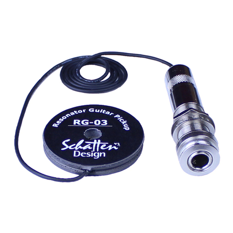
Schatten Design RG-03 User manual

RG-03 M-Kit Jack Change Instructions
M-Kits include everything required to convert an existing RG-03 to a RG-03M System, except for some basic hand tools and a
soldering iron and solder. Please read these instructions through before beginning the conversion.
Starting Installation
1) Slack off the strings, remove them from the tailpiece and tape them away
from the cover plate. Remove the cover plate screws and set the cover plate
aside. Remove the tailpiece and resonator cone complete with the spider bridge.
RG-03
The RG-03 was supplied with an endpin jack. Adding the M microphone to
the second channel of the output is quite straight forward.
1) Remove the jack from the instrument.
2) Unscrew the jack cover and insert the bare end of the mic cable through the
hole in the cover.
3) The mic cable is a shielded 2 conductor cable. It is necessary to strip the
outer black insulation from the other end of the cable.
4) Strip about 3/4" of the black insulation, exposing the ground (-) shield wrap.
Twist the wrap to form a single lead and tin it.
5) The inner insulated (+) wire is now exposed. Strip it back about one-quarter inch and tin it.
6) Pry open the two teeth on the cable clamp that are holding the pickup lead wire in place.
7) Solder the mic cable (+) to the lug as shown.
8) Solder the ground (-) to the cable clamp as shown.
9) Bend the teeth of the cable clamp back down around the 2 lead wires and screw the jack cover back in place.
10) Reinstall the jack on the instrument.
11) Continue the installation as detailed in the RG-03M installation instructions.
RG-03 Std
The RG-03 Std was supplied with a black ABS jack assembly with a 1/4" jack
inside
1) Remove the jack assembly from the instrument.
2) Remove the two screws holding the cover on the jack body.
3) Remove the nut and washers that are holding the black jack in place. Note that
the contact closest to the bottom of the jack box is bent upwards slightly so that it
won’t come into contact with the ground shield coating of the box.
4) Drill a second 5/32" hole through the top in the area under the tailpiece. Take an
old guitar string and insert it down through the hole in the top. Tape the end of the
mic lead wire to the string and pull it back through the hole.
5) Remove the jack from the jack assembly box and clip the wires soldered to jack
as close to the jack as possible. Slide the pickup lead wire out of the jack assembly
box and remove the small rubber grommet from the box.
a) Insert the pickup lead wire back into the box.
b) Strip about 3/4" of the black insulation, exposing the ground (-) shield wrap. Twist the wrap to form a single lead
and tin it.
c) The inner insulated (+) wire is now exposed. Strip it back about one-quarter inch and tin it. Solder the inner lead
(+) from the pickup to the new jack as shown.
d) Solder the ground shield from the pickup to the new jack as shown.
d) The mic cable is a shielded 2 conductor cable. Insert the mic cable through the same hole in the box wall that the
pickup goes through. It is necessary to strip the outer black insulation from the bare end of the cable. Strip about 3/4" of the
black insulation, exposing the ground (-) shield wrap. Twist the wrap to form a single lead and tin it.
e) The inner insulated (+) wire is now exposed. Strip it back about one-quarter inch and tin it.
f) Solder the (+) mic lead to the jack as shown. Solder the mic outer shield (-) ground to the jack as shown.
g) Reinstall the jack back into the box with the lug for the pickup closest to the bottom of the box. Make sure that the
solder lug is bent up slightly so that it cannot come into contact with the ground shield coating of the box.
h) Put the cover back on the jack assembly and reinstall it on the instrument.
i) Continue installation as detailed in the RG-03M installation instructions.

RG-03 Pro
The RG-03 Pro was supplied with a black ABS jack body with a volume control and black 1/4" jack.
Note: The Mini Pre 2 has volume controls for the microphone as well as for the pickup. You have a choice as to whether you
want to continue to use the volume control on the jack assembly or not. If you want to use it, it will continue to work but it
will affect only the pickup. Diagrams for both iterations are shown below
1) Remove the jack assembly from the instrument.
2) Remove the two screws holding the cover on the jack body.
3) Remove the nut and washers that are holding the black jack in place. Note that the contact closest to the bottom of the
jack box is bent upwards slightly so that it won’t come into contact with the ground shield coating of the box.
4) Drill a second 5/32" hole through the top in the area under the tailpiece. Take an old guitar string and insert it down
through the hole in the top. Tape the end of the mic lead wire to the string and pull it back through the hole.
5) Remove the jack from the jack assembly box and clip the wires soldered to jack as close to the jack as possible. Slide the
pickup lead wire out of the jack assembly box and remove the small rubber grommet from the box.
6) Wiring for leaving the volume control functional for the pickup:
a) Remove the jack from the jack assembly
box and clip the wires soldered to jack as close to the
jack as possible. Slide the pickup lead wire out of the
jack assembly box and remove the small rubber
grommet from the box. Insert the pickup lead wire
back into the box.
b) Tin the lugs on the new jack. Solder the
ground lead from the back of the pot to the new jack
as shown.
c) Solder the ground shield from the pickup to
the new jack as shown.
d) The mic cable is a shielded 2 conductor
cable. Insert the mic cable through the same hole in
the box wall that the pickup goes through. It is
necessary to strip the outer black insulation from the
bare end of the cable. Strip about 3/4" of the black
insulation, exposing the ground (-) shield wrap. Twist the wrap to form a single lead and tin it.
e) The inner insulated (+) wire is now exposed. Strip it back about one-quarter inch and tin it.
f) Solder the (+) mic lead to the jack as shown. Solder the mic outer shield (-) ground to the jack as shown.
g) Reinstall the jack back into the box with the lug for the pickup closest to the bottom of the box. Make sure that the
solder lug is bent up slightly so that it cannot come into contact with the ground shield coating of the box.
h) Put the cover back on the jack assembly and reinstall it on the instrument.
i) Continue installation as detailed in the RG-03M installation instructions.
7) Wiring for disconnecting the volume control:
a) Remove the jack from the jack assembly box and
clip the wires soldered to jack as close to the jack as possible.
Slide the pickup lead wire out of the jack assembly box and
remove the small rubber grommet from the box. Insert the
pickup lead wire back into the box.
b) Strip about 3/4" of the black insulation, exposing
the ground (-) shield wrap. Twist the wrap to form a single
lead and tin it.
c) The inner insulated (+) wire is now exposed. Strip it
back about one-quarter inch and tin it. Solder the inner lead
(+) from the pickup to the new jack as shown.
d) Solder the ground shield from the pickup to the
new jack as shown.
d) The mic cable is a shielded 2 conductor cable. Insert the mic cable through the same hole in the box wall that the
pickup goes through. It is necessary to strip the outer black insulation from the bare end of the cable. Strip about 3/4" of the
black insulation, exposing the ground (-) shield wrap. Twist the wrap to form a single lead and tin it.
e) The inner insulated (+) wire is now exposed. Strip it back about one-quarter inch and tin it.
f) Solder the (+) mic lead to the jack as shown. Solder the mic outer shield (-) ground to the jack as shown.
g) Reinstall the jack back into the box with the lug for the pickup closest to the bottom of the box. Make sure that the
solder lug is bent up slightly so that it cannot come into contact with the ground shield coating of the box.
h) Put the cover back on the jack assembly and reinstall on the instrument.
i) Continue installation as detailed in the RG-03M installation instructions.
Rev. 04-12-2014

fig 1
RG-03M Resonator Guitar Pickup & Condenser Mic System For Spider Bridged Instruments
The M microphone in the RG-03M system was designed to add air, clarity and sound quality to the normal attributes
of the RG-03 pickup sensor. The M microphone was not designed to be, nor is it intended to be used as a stand-alone
microphone.
Important:Please read these instruction through first before installing this system.
Starting Installation
1) Slack off the strings, remove them from the tailpiece and tape them away from the cover plate. Remove the cover
plate screws and set the cover plate aside. Remove the tailpiece and resonator cone complete with the spider bridge
and set the rest of the guitar aside.
2) Remove the screw that connects the spider bridge to the resonator cone. There are two replacement screws
provided, one is a 3 mm. metric, the other is a 4-40. Check to see which of the two screws fits your resonator cone
properly. The correct screw should thread in very easily, do not force it. Also, make sure that the head of the
replacement screw fits into the saddle slot properly. If the screw head is too large
to fit in the slot, grind off or file away whatever small amount of the head
diameter is necessary to make it fit in the slot properly. Once the screw is properly
fitted, use it to snugly attach the spider to the cone.
3) It is suggested that at this point you reinstall the cone with the spider and
saddles into the instrument (leave the cover plate off), reinstall the strings, tune
the instrument and tighten the machine screw that connects the spider to the cone
so that the sound and response is set to original levels. When this is done, remove
the strings, set the cone and spider assembly on your workbench and set the rest
of the instrument aside.
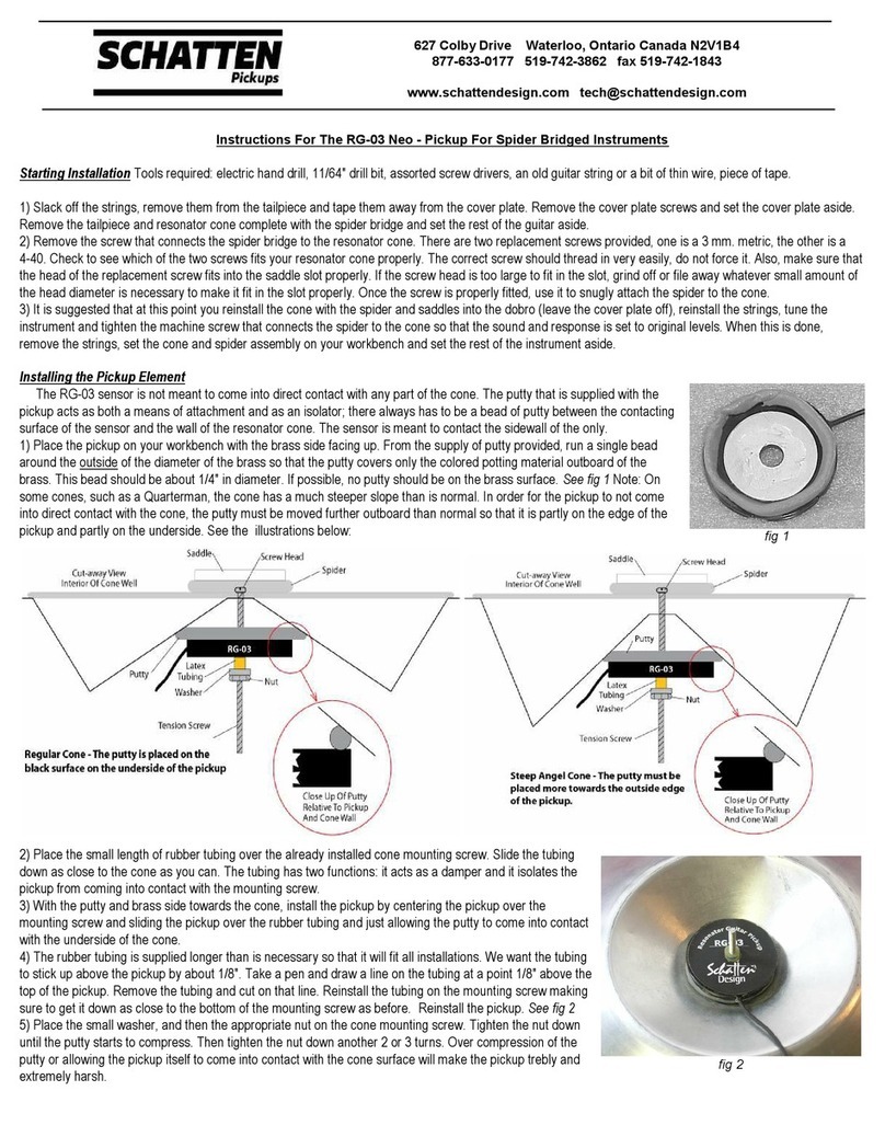
Installing the Pickup Element
The RG-03 sensor is not meant to come into direct contact with any part of the
cone. The putty that is supplied with the pickup acts as both a means of
attachment and as an isolator; there always has to be a bead of putty between the
contacting surface of the sensor and the wall of the resonator cone. The sensor is meant to contact the sidewall of the
only.
1) Place the pickup on your work surface with the brass side facing up. From the supply of putty provided, run a
single bead around the outside of the diameter of the brass so that the putty covers only the black colored potting
material outboard of the brass. This bead should be about 1/4" in diameter. If possible, no putty should be on the
brass surface. See fig 1 Note: On some cones, such as a Quarterman, the cone has a much steeper slope than is
normal. In order for the pickup to not come into direct contact with the cone, the putty must be moved further
outboard than normal so that it is partly on the edge of the pickup and partly on the underside. See illustrations
below:

2) Place the small length of rubber tubing over the already installed cone
mounting screw. Slide the tubing down as close to the cone as you can.
The tubing has two functions: it acts as a damper and it isolates the
pickup from coming into contact with the mounting screw.
3) With the putty and brass side towards the cone, install the pickup by
centering the pickup over the mounting screw and sliding the pickup over
the rubber tubing and just allowing the putty to come into contact with
the underside of the cone.
4) The rubber tubing is supplied longer than is necessary so that it will fit
all installations. We want the tubing to stick up above the pickup by
about 1/8". Take a pen and draw a line on the tubing at a point 1/8"
above the top of the pickup. Remove the tubing and cut on that line.
Reinstall the tubing on the mounting screw making sure to get it down as
close to the bottom of the mounting screw as before. Reinstall the
pickup. See fig 2
5) Place the small washer, and then the appropriate nut on the cone
mounting screw. Tighten the nut down until the putty starts to compress. Then tighten the nut down another 2 or 3
turns. Over compression of the putty or allowing the pickup itself to come into contact with the cone surface will make
the pickup trebly and extremely harsh.
M Condenser Microphone Installation:
1) The suggested mounting position for the microphone is as
shown, just below the cut for the lip of the cone. The mic will be
generally be placed 3/8" down from that cut.
2) Both putty and 3M VHB mounting tape is supplied for installing
the microphone. The suggested method of mounting the mic is to
use the supplied putty.
3) Roll up a small ball of the putty (about 3/8" in diameter) and
spread it out evenly on the flat surface of the microphone mount.
Press the microphone mount firmly against the side wall of the well.
It may be necessary to press the assembly against the wall several
times over ten or fifteen minutes until the putty takes a set.
4) If the wall surface is clean and smooth, the VHB may be used for
mounting if desired. Alternatively, a small screw may be used to
affix the mic to the wall using the small hole in the mount.
Installing the Jack
Note: You have the option of permanently installing the supplied jack as an endpin jack, as a side jack or, if you
don’t wish to drill a hole through the butt or side of the instrument, the jack may be hung from an existing tailpiece
screw or strap button.
For endpin jack use
1) Remove the existing strap button. If the strap button screw also functioned to hold the tailpiece in place, then
reinstall the screw without the strap button.
2) Measure the actual depth of your resonator cone (it is generally in the range of 2""). Allowing for the amount that
the resonator cone is recessed into the top (usually about 1/8" to 1/4"), add that to the depth figure for the cone
(usual total 2 1/4"). Add extra 1/2" for clearance and measure down from the top of the instrument about 2 3/4".
3) Drill a pilot hole through the end block approximately 3/16" in diameter in the area you wish to place the end pin
jack.
4) Using a fluted burr, chamfer the edges of the hole so that you will not damage the finish of the instrument when
you use the larger sizes of bits required.
5) Drill through the guitar end block using a 3/8" bit and re-chamfer the hole. Repeat drilling with a 31/64" bit to
complete the drilling operations.
7) Remove the Outer strap button, and the small nut and washer from the endpin jack or preamp. Reach inside the
instrument and poke the endpin jack part through the drilled hole in the end block. The jack should protrude
approximately 5/16" outside the guitar. Reinstall the flat washer and small nut.
8) Insert a small allen wrench or other small round (like a drill bit) through the 2 holes in the end of the endpin jack
to keep the jack assembly from rotating; tighten the small nut.
For side jack use
1) Drill a 3/8" diameter hole in the side wall of the instrument where you want to mount the jack.
2)Remove the outer strap button, small nut and washer from the endpin jack. Reach inside the instrument and poke
the jack through the drilled hole in the side. Reinstall the flat washer and nut and tighten the jack.
fig 2


For hanging jack use
1) Drill two holes 5/32" (0.070") in diameter on the face of the instrument directly under the tailpiece. The holes
should be placed about 1 ½" from the end of the guitar so that it misses the end block.
2) Unsolder the pickup and mic lead wiring from the endpin jack and clip the ends of the wires clean.
3) Take an old guitar string and insert it down through the hole in the top. Tape the end of the pickup lead wire to the
string and pull it back through the hole. Repeat for the mic lead wire. Insert both lead wires through the endpin jack
cover.
4) For the pickup lead wire: strip about
3/4" of the black insulation, exposing the
ground (-) shield wrap. Twist the wrap to
form a single lead and tin it.
5) The inner insulated (+) wire is now
exposed. Strip it back about one-quarter
inch and tin it.
6) Solder the pickup lead wire (+) to the
lug as shown.
7) Solder the ground (-) to the cable
clamp as shown.
8) Repeat steps 6 and 7 for the mic lead wire.
9) Crimp the wire holder on the jack closed around the two lead wires. Tighten
down the endpin jack cover.
10) Place the clip around the jack and install the clip as shown.
Mini Pre 2 Preamp
Preamp Configuration: as shipped, channel one will preamp the
pickup sensor, while channel two will power the condenser
microphone and preamp the mic signal. A black jumper is fitted
over the pins at ‘A’ for this configuration.
Should you ever need to use the preamp with an
instrument that has two pickups, the second channel can be
reset for that second pickup by moving the black jumper from
‘A’ and fitting it over the pins at ‘B’. With the jumper set at ‘B’,
power is no longer supplied to the second channel.
1/4" Input Jack
The input jack is set up to receive a stereo TRS plug. Tip
will transmit (+) from the pickup sensor to channel one. Ring
will transmit (+) from the mic to channel two. Sleeve is the
common ground. If you plug a mono plug into the input, the tip
will transmit the (+) from the pickup sensor to channel one.
Channel two will not function with a mono plug. Using a mono
plug into the input will not harm the preamp but it will bring
the battery down fractionally quicker than normal.
1/4" Output Jack
The output jack feeds out a mono signal only. The signal is
not a balanced signal.
Input Gain Trim Pots
As shipped, channel one gain is set to approximately 15% and channel two gain is set to approximately 25%.
These settings are about what the input gains might be set at for most installations. You may very well have to
change these settings to suit your instrument. Important: The trim pots must be adjusted using a very small jewellers
slotted screwdriver.
Setting Up The Preamp
1) Remove the back cover and attach a 9 volt alkaline or lithium battery (not included).
2) Turn the 2 external volume controls fully off, plug in the supplied stereo TRS cable to both the banjo jack assembly
and the input of the Mini Pre 2.
3) Run a normal 1/4" cord from the Mini Pre 2 output to the input of your amp. Set the amp at a low setting.
4) Turn the volume control for channel one to a comfortable sound level.
5) Turn the volume control for channel two to a comfortable sound level.
6) You should now assess the relative sound levels of the pickup sensor and the microphone and adjust the input gain
trim pots on the preamp circuit board as necessary.
7) Install the belt clip to the back cover of the preamp using the two supplied screws. Reinstall back cover.
8) Note that the battery within the preamp is turned on only when a plug is inserted into the output jack.

Preamp Specifications:
Input Impedance: each channel, up to 10 MOhm
Output Impedance: less than 3.5 kOhm
Input Gain: each channel 0 to 20 db via trim pots on circuit board
Battery Life: 9 volt alkaline - 1300 hours for pickup/mic configuration Do Not Use Rechargeable Batteries
Finishing up with the instrument
1) Prior to reinstalling the resonator assembly, the supplied wire clips should be installed in the well area to hold down
any excess wire.
2) At this point it is suggested that you reinstall the resonator into the instrument (without the cover plate). Reinstall
the highest treble string and lowest bass string and tune to pitch. Plug into your amp. Check that the quality of the
sound is good and that string output is balanced. If everything is fine, take off the strings and remove the resonator
from the instrument.
Important: Put a small bit of masking tape or scotch tape or a drop of glue on the exposed part of the mounting
screw so that the nut cannot back off or rattle.
3) Reinstall the resonator assembly and the cover plate.
4) Restring, tune, and check.
Warranty
We warrant to the original purchaser that our pickups are free from defects in materials and workmanship for a period of 2 (two)
years. Should a product fail to perform properly within the specified warranty period you may contact your dealer or Schatten Design
for instructions. No product will be accepted for warranty return by Schatten Design without a Return Authorization number
Rev 04-12-2014
This manual suits for next models
3
Table of contents
Other Schatten Design Accessories For Musical Instruments manuals
Popular Accessories For Musical Instruments manuals by other brands

ToneShapers
ToneShapers ToneShaper instruction manual

Becos
Becos TS8-MS Overdrive Midi Switching quick start guide

Wenger
Wenger Gearboss Center Soft Divider Series owner's manual

Konig & Meyer
Konig & Meyer 12170 manual

Perry's Music
Perry's Music ChordBuddy user guide

Mojotone
Mojotone NC-1 Quick installation