Schebler PA Operation and maintenance manual

1
INSTALLATION INSTRUCTIONS
OPERATION AND MAINTENANCE MANUAL
MODELS PA, P1, P2, P2A and P4 Chimney System
MODELS SW, PA, P1, P2, P2A, P4, FG and SV Grease Duct System
A MAJOR CAUSE OF CHIMNEY RELATED FIRES
IS FAILURE TO MAINTAIN REQUIRED
CLEARANCES (AIR SPACES) TO COMBUSTIBLE
MATERIALS. IT IS OF UTMOST IMPORTANCE
THAT THIS CHIMNEY BE INSTALLED ONLY IN
ACCORDANCE WITH THESE INSTRUCTIONS.
IMPORTANT: DO NOT INSTALL CHIMNEY WITHOUT
FIRST READING THESE INSTRUCTIONS.
USC

2
TABLE OF CONTENTS
General 3
ULListingUSAandCanada 3
ChimneyApplications 3
TerminationHeightRequirements 3
ChimneyEnvironment 3
ClearancesandEnclosures 4
PartIdentification 6
SupportLimits 5&19
SeismicRequirements 6
Individual Part Installation 7
BasicPipeandFittingAssembly 7
JointSealant 7
Adjustable Lengths (18AL, 22AL, 30AL and 45AL) 8
BellowsSections 9
BoilerAdapterKits(BKFandBKR) 9
90DegreeTee(90T) 10
Elbows(30L,45Land90L) 10
45 Degree Lateral Tee (45LT) 10
90 Degree Wye (90Y) 10
Variable Length Section (18VS, 29Vs and VS) 11
SupportPlate(SP) 11
WallSupport(WS) 12
WallGuide(WG) 12
FloorRoofGuide(FRG) 12
FullAngleRing(FR) 13
HalfAngleRing(HR) 13
Flashing(FL) 13
RainCollar(RC) 13
InsulatedThimble(IT) 13
EndCap(EC) 13
DrainTeeCap(DTC) 13
RainCap(CC) 14
TopSection(TS) 14
ExitCone(EXC) 14
GuySection(GS) 15
Engine Exhaust Installation 15
JointSealant 15
Expansion 15
Support 15
VariableLengthvs.SpecialLengthSections 15
SystemLayout 15
ManifoldSystems 15
PressureReliefValve 16
Operating Precautions 16
Maintenance 16
Grease Ducts 17
Applications 17
Slope 17
Clearances 18
InspectionandCleanout 20
HoodTransitions 20
FireStop(FS) 21
RoofTerminations 21
WallTerminations 22
ProperMaintenanceandSafety 22
AutomaticCleaningSystems 23
FireExtinguishingEquipment 23
GreaseTraps 23
Maintenance 23

3
GENERAL
TheseinstructionscoverScheblerChimneyandGreaseDuct
ModelsSW,PA,P1,P2,P2A,P4,Fyreguard™,(FG)and
Slimvent™(SV).Forthepurposesofthismanual,allmodelswill
betreatedtogether.Differencesinclearances,supportlimits
andinstallationofthevariousmodelswillbeshownwhere
needed.
ULLISTING–USAandCANADA
ModelsSW,PA,P1,P2,P2AandP4areULListedunderfile
numberMH17739asBuildingHeatingApplianceChimneys
(1000°F),1400°FChimneysandasGreaseDuct.Theyarealso
approvedtobeartheULMarkforCanadaas560°CChimneys,
760°CChimneysandasGreaseDuct.
CHIMNEYAPPLICATIONS
‐ModelsPA,P1,P2,P2AandP4Chimneysaresuitableforuse
withBuildingHeatingAppliancesandotherLowHeat
AppliancesasdescribedintheChimneySelectionChartofthe
NFPA211,whichproduceexhaustfluegasesnotexceeding
1000°F(560°C)undercontinuousoperation.Theyarealso
suitableforexhauststacks,industrialovens,furnaces,and
processductingwhichdoesnotexceedthe1400°F(760°C).
‐Thesechimneysaretobeinstalledasrequiredformetal
chimneys.Theyarenottobeenclosedwithincombustible
construction.Anunenclosedchimneymaybeplacedadjacent
towallsofcombustibleconstructionattheclearancesspecified
oneachchimneysectionandintheindividuallisting.Consult
theAuthorityHavingJurisdictionaboutrestrictionsand
installationinspectioninyourarea.
-These Chimneys are intended for use as complete systems
connecting the appliance to the outdoors, while operating
under positive forced draft, negative induced draft or
neutral gravity flow internal pressure conditions.
-This chimney system is rated for a maximum 60 inches
water column internal pressure when used in Positive
Pressure Applications.
-Chimney systems are to be sized in accordance with the
ASHRAE Handbook, Equipment Volume, the appliance
manufacturer’s instructions, or by contacting The Schebler
Company, Chimney Systems, 5665 Fenno Road,
Bettendorf, Iowa 52722.
-Refer to The Schebler Company Chimney Systems
catalog for description of all necessary parts.
GREASE DUCT
Refer to the Grease Duct Installation Supplement,
beginning on page 17 for information specific to grease
duct installation. The basic installation information in
these instructions applies to both chimneys and grease
duct.
TERMINATION HEIGHT REQUIREMENTS
Chimneys are to terminate a minimum of 3-ft. (0.92 m)
above the highest point of the roof penetration and 2-ft.
(0.61m) minimum above any portion of a building within
10-ft (3.1 m) horizontally. Consult the Authority Having
Jurisdiction about restrictions in your area. See NFPA 211.
Figure 1 – Pitched Roof Termination Height
Figure 2 – Flat Roof Termination Height
CHIMNEY ENVIRONMENT
It is suggested that a chimney being installed in a
corrosive atmosphere be constructed of Type 316
stainless steel or a more corrosive resistant material.
Use of chemicals containing chlorine or chlorides in the
vicinity of equipment or the presence of these
substances in the fuel or combustion air supply may
lead to early deterioration of the chimney. Chemicals
which may cause attack on chimney materials are:
Chlorinated or halogenated dry cleaning
solutions
fluorocarbon refrigerants
fluorocarbon aerosol propellants
vinyl plastics when burned
chlorine bleach and cleaning solutions
titanium tetrachloride
plating or etching baths and solutions
Any of these chemicals passing through the combustion
process produce acids which can corrode heating
equipment and the chimney. If a corrosive
environment is suspected, please contact The Schebler
Company for suggestions on alternate materials for
liners and shells which will safely handle corrosive
environments.

4
CLEARANCES AND ENCLOSURES
CAUTION – DO NOT ENCLOSE IN A CHASE OR
PASSAGEWAY MADE FROM WOOD OR ANY
OTHER COMBUSTIBLE MATERIAL. DO NOT
PLACE ANY TYPE OF INSULATION OR
COMBUSTIBLE MATERIALS IN THE REQUIRED
CLEARANCE SPACES SURROUNDING THE
CHIMNEY.
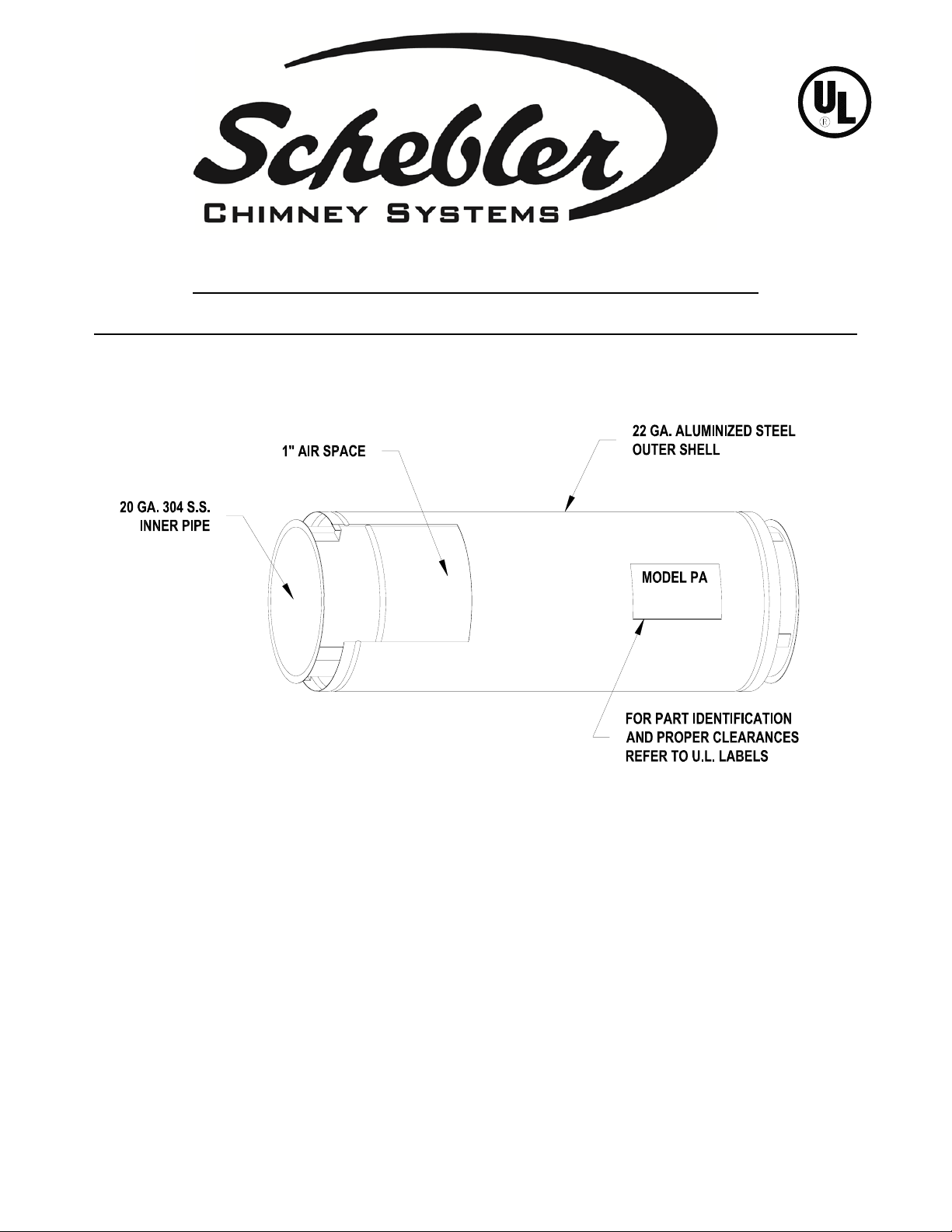
These chimneys are intended to be installed unenclosed or
with non-combustible enclosures. Schebler Chimney
Models SW, PA, P1, P2, P2A and P4 are not for use in one
or two-family dwellings.
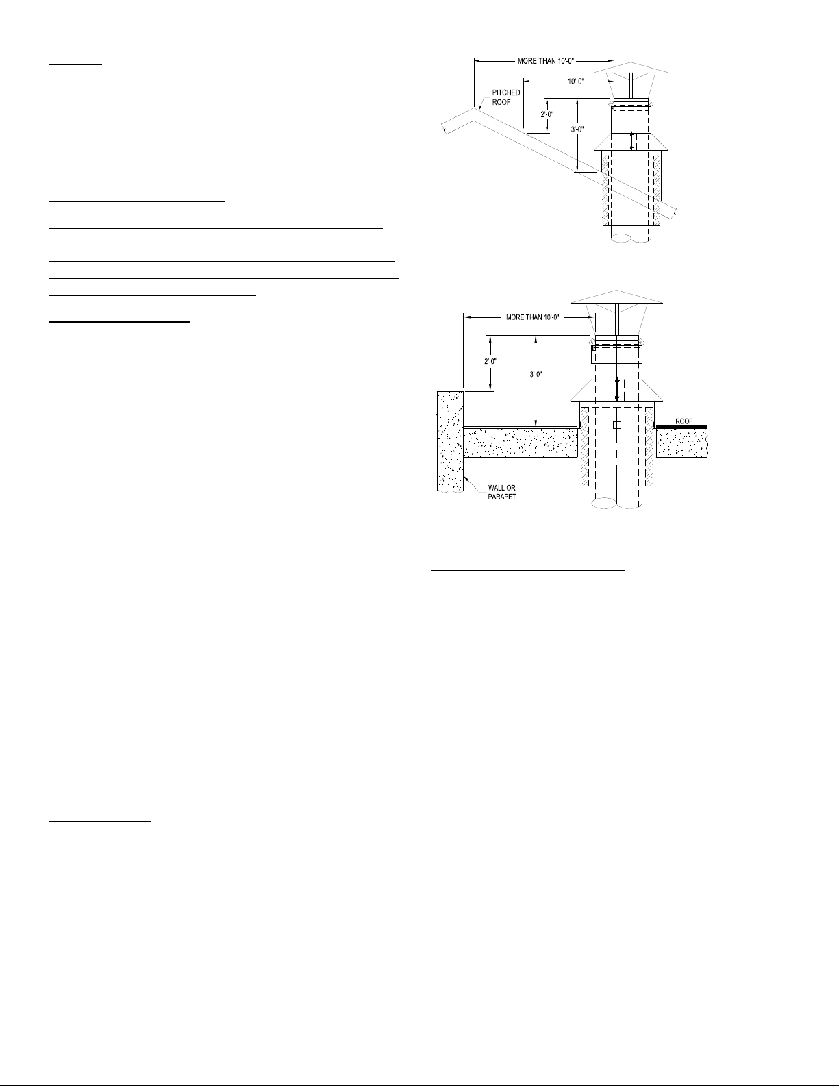
If the chimney passes through any zone or story of a
building above that on which the connected appliance is
located, it is to be enclosed in non-combustible
construction having a fire rating equal to or greater than
that of the floor or roof assemblies through which it
passes. NOTE: Always check with the Authority Having
Jurisdiction for material with an appropriate fire rating. If
a portion of the chimney passes between a dropped ceiling
and roof, that portion is to be enclosed in a fire rated
enclosure or proper clearance to combustibles are
maintained. Chimneys are not intended to pass through
combustible walls. Any wall through which the chimney
passes must be of non-combustible construction unless
proper clearance to combustibles are maintained.
Chimneys installed in open rooms or fully ventilated areas
on the same story as the equipment connected to it shall
have a minimum clearance to combustibles as shown in
the following tables: Refer to grease duct section for
applications and clearances.
Clearances to non-combustibles shall be as necessary for
installation, inspection and maintenance.
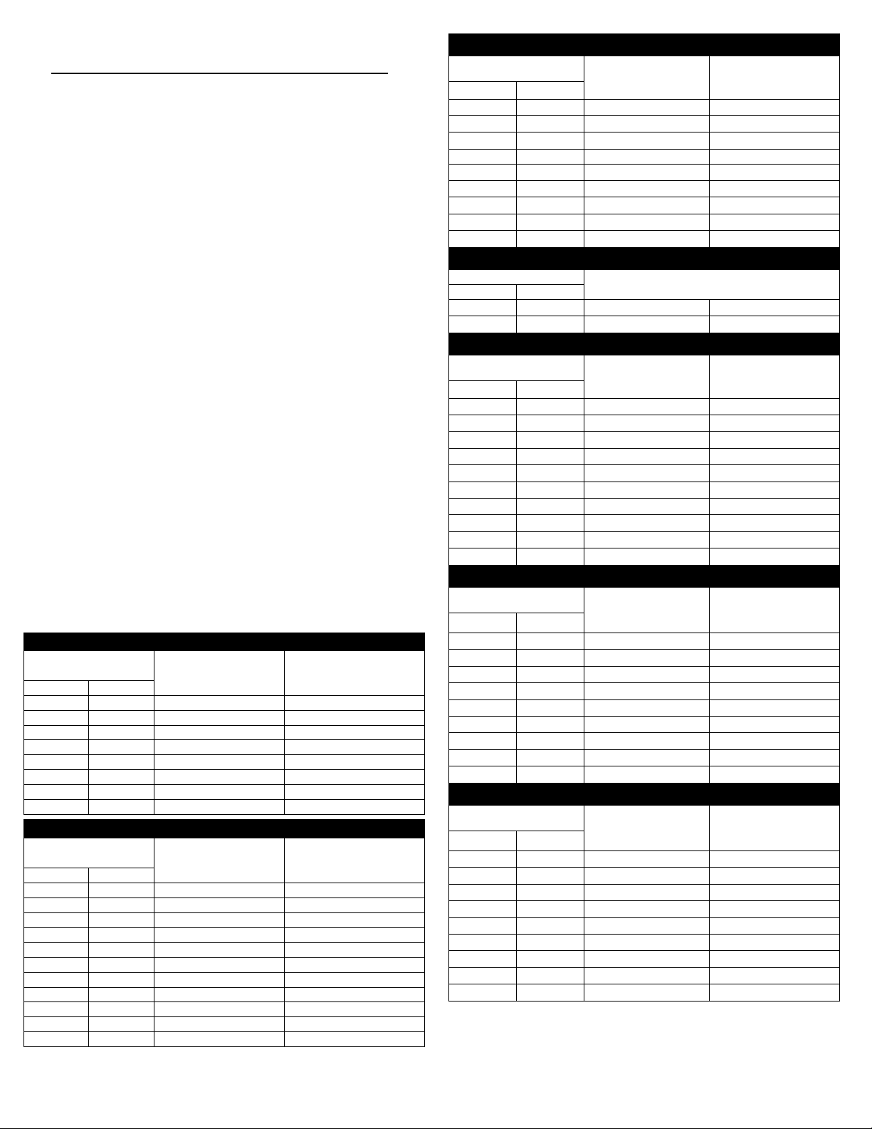
MODEL SW CHIMNEY CLEARANCES
Inside Diameter Building Heating
Appliance (1000°F)
(560°C) Chimney
1400° Fahrenheit
(760°C) Chimney
inches mm
5-6 127-152 18” (457mm) 18” (457mm)
7-16 178-406 18” (457mm) 18” (457mm)
17-20 431-508 18” (457mm) 18” (457mm)
21-24 533-610 18” (457mm) 18” (457mm)
25-28 635-711 18” (457mm) 18” (457mm)
29- 32 736-813 18” (457mm) 18” (457mm)
33- 36 838-914 18” (457mm) 18” (457mm)
41- 48 1041-1219 18” (457mm) 18” (457mm)
MODEL PA CHIMNEY CLEARANCES
Inside Diameter Building Heating
Appliance (1000°F)
(560°C) Chimney
1400Fahrenheit
(760°C) Chimney
inches mm
5-6 127-152 6” (152mm) 7” (178mm)
7-12 178-305 7” (178mm) 8” (203mm)
13-16 330-406 8” (203mm) 9” (229mm)
17-20 431-508 9” (229mm) 10” (254mm)
21-24 533-610 10” (254mm) 11” (279mm)
25-28 635-711 11” (279mm) 12” (305mm)
29-32 736-813 12” (305mm) 13” (330mm)
33-36 838-914 13” (330mm) 14” (356mm)
37-40 940-1016 14” (356mm) 15” (381mm)
41-44 1041-1118 15” (381mm) 16” (406mm)
45-48 1143-1219 18” (457mm) 20” (508mm)
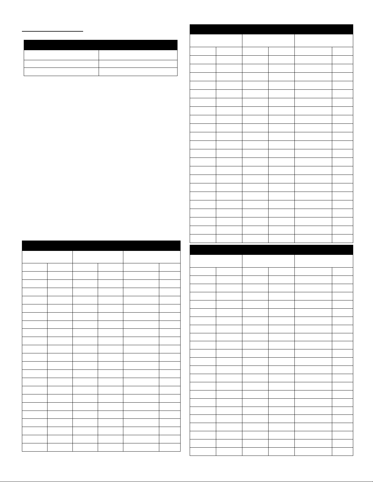
MODEL P1 UL 103 CHIMNEY CLEARANCES
Inside Diameter Building Heating
Appliance (1000°F)
(560°C) Chimney
1400Fahrenheit
(760°C) Chimney
inches mm
6-14 152-356 1” (25mm) 1” (25mm)
15-20 381-508 2” (51mm) 2” (51mm)
21-24 533-610 3” (76mm) 3” (76mm)
25-28 635-711 4” (102mm) 4” (102mm)
29-33 736-838 5” (127mm) 5” (127mm)
34-38 864-965 6” (152mm) 6” (152mm)
39-41 991-1041 7” (178mm) 7” (178mm)
42-45 1067-1143 8” (203mm) 8” (203mm)
46-48 1168-1219 9” (229mm) 9” (229mm)
MODEL P1 UL 103HT CHIMNEY CLEARANCES
Inside Diameter 1400Fahrenheit (760°C) Chimney
inches mm
5-12 127-305 1” (25mm)
13-24 330-610 2” (51mm)
MODELS P2 CHIMNEY CLEARANCES
Inside Diameter Building Heating
Appliance (1000°F)
(560°C) Chimney
1400Fahrenheit
(760°C) Chimney
inches mm
5-6 127-152 1/2” (13mm) 1/2” (13mm)
7-10 178-254 1” (25mm) 1” (25mm)
11-14 279-356 2” (51mm) 2” (51mm)
15-18 381-457 3” (76mm) 3” (76mm)
19-24 483-610 4” (102mm) 4” (102mm)
25-28 635-711 5” (127mm) 5” (127mm)
29-32 736-813 6” (152mm) 6” (152mm)
33-36 838-914 7” (178mm) 7” (178mm)
37-40 940-1016 8” (203mm) 8” (203mm)
41-48 1041-1219 9” (229mm) 9” (229mm)
MODEL P2A CHIMNEY CLEARANCES
Inside Diameter Building Heating
Appliance (1000°F)
(560°C) Chimney
1400° Fahrenheit
(760°C) Chimney
inches mm
5-6 127-152 1” (25mm) 2” (51mm)
7-16 178-406 2” (51mm) 3” (76mm)
17-20 431-508 3” (76mm) 4” (102mm)
21-24 533-610 4” (102mm) 5” (127mm)
25-28 635-711 5” (127mm) 6” (152mm)
29- 32 736-813 6” (152mm) 7” (178mm)
33- 36 838-914 7” (178mm) 8” (203mm)
37- 40 940-1016 8” (203mm) 9” (229mm)
41- 48 1041-1219 11” (279mm) 12” (305mm)
MODEL P4 CHIMNEY CLEARANCES
Inside Diameter Building Heating
Appliance (1000°F)
(560°C) Chimney
1400° Fahrenheit
(760°C) Chimney
inches mm
5-6 127-152 1” (25mm) 2” (51mm)
7-16 178-406 2” (51mm) 3” (76mm)
17-20 431-508 3” (76mm) 4” (102mm)
21-24 533-610 4” (102mm) 5” (127mm)
25-28 635-711 5” (127mm) 6” (152mm)
29- 32 736-813 6” (152mm) 7” (178mm)
33- 36 838-914 7” (178mm) 8” (203mm)
37- 40 940-1016 8” (203mm) 9” (229mm)
41- 48 1041-1219 11” (279mm) 12” (305mm)

5
LIMITATIONS
If the height above the roof line is less than that
specified above, no guying or bracing is required.
However, a Floor/Roof Guide (FRG), Support Plate
(SP) or Full Ring (FR) at the roof line is necessary to
protect the Flashing (FL) from side loads caused by
wind. For heights above the roof line greater than that
shown above, the chimney must be guyed or braced.
Guying or bracing is accomplished by use of the Guy
Section (GS) Full Ring (FR) or Wall Guide (WG). Guy
wires or braces are to be attached to the horizontal
flanges of the Guy Section. While 3 guys are usually
sufficient, it is recommended that 4 equally spaced
wires at an angle of 45° from the vertical be utilized.
The cables and guys must be slightly loose to allow for
the thermal expansion. Rigid bracing requires two
braces with not less than 60° angle between them. The
braces must be attached to a Guy Section (GS) or Full
Ring (FR).
Maximum height above top lateral brace or guy
Chimney Inside Diameter Maximum Height
6” - 10” (152-254mm) 8 feet (2.44m)
12” - 48” (305-1219mm) 12 feet (3.66m)
MODEL SW SUPPORT LIMITS
SECTION INSIDE
DIA.
SUPPORT PLATE
(SP) WALL SUPPORT (WS)
inches mm feet Meters feet meters
6 152 306 93.27 193 58.83
8 203 269 81.99 171 52.12
10 254 255 77.72 164 49.99
12 305 237 72.24 153 46.63
14 356 227 69.19 148 45.11
16 406 213 64.92 140 42.67
18 457 201 61.26 134 40.84
20 508 192 58.52 129 39.32
22 559 180 54.86 123 37.49
24 610 172 52.43 119 36.27
26 660 161 49.07 113 34.44
28 711 151 46.02 108 32.92
30 762 142 43.28 103 31.38
32 813 161 49.07 120 36.58
34 864 151 46.02 114 34.75
36 914 113 34.44 88 26.82
38 965 101 30.78 81 24.69
40 1016 93 28.35 77 23.47
42 1067 85 25.91 73 22.25
44 1118 76 23.16 68 20.73
46 1168 68 20.73 64 19.51
48 1219 60 18.29 60 18.29
MODEL PA SUPPORT LIMITS
SECTION INSIDE
DIA.
SUPPORT PLATE
(SP) WALL SUPPORT (WS)
inches mm feet meters feet meters
6 152 306 93.27 193 58.83
8 203 269 81.99 171 52.12
10 254 255 77.72 164 49.99
12 305 237 72.24 153 46.63
14 356 227 69.19 148 45.11
16 406 213 64.92 140 42.67
18 457 201 61.26 134 40.84
20 508 192 58.52 129 39.32
22 559 180 54.86 123 37.49
24 610 172 52.43 119 36.27
26 660 161 49.07 113 34.44
28 711 151 46.02 108 32.92
30 762 142 43.28 103 31.38
32 813 161 49.07 120 36.58
34 864 151 46.02 114 34.75
36 914 113 34.44 88 26.82
38 965 101 30.78 81 24.69
40 1016 93 28.35 77 23.47
42 1067 85 25.91 73 22.25
44 1118 76 23.16 68 20.73
46 1168 68 20.73 64 19.51
48 1219 60 18.29 60 18.29
MODEL P1 SUPPORT LIMITS
SECTION INSIDE
DIA.
SUPPORT PLATE
(SP) WALL SUPPORT (WS)
inches mm feet meters feet meters
6 152 270 82.3 171 52.12
8 203 244 74.37 156 47.55
10 254 230 70.1 147 44.81
12 305 213 64.92 138 42.06
14 356 202 61.57 132 40.23
16 406 192 58.52 127 38.71
18 457 180 54.86 120 36.58
20 508 172 52.43 116 35.36
22 559 163 49.68 111 33.83
24 610 155 47.24 107 32.61
26 660 146 44.5 103 31.39
28 711 136 41.45 97 29.57
30 762 128 39.01 93 28.35
32 813 145 44.2 108 32.92
34 864 135 41.15 102 31.09
36 914 103 31.39 80 24.38
38 965 94 28.65 75 22.86
40 1016 86 26.21 71 21.64
42 1067 78 23.77 67 20.42
44 1118 71 21.64 63 19.2
46 1168 63 19.2 59 17.98
48 1219 56 17.07 56 17.07

6
SEISMIC REQUIREMENTS
All Schebler Chimney Systems models and installations
have been tested, listed and are manufactured under strict
guidelines of the Underwriters Laboratories Inc. Standard
for Safety 103 listing. Schebler Chimney Systems have
passed these tests and are approved for all installations
according to these standards, and do not require special
seismic bracing under normal installation requirements.
Schebler Chimney system assemblies and parts, when
installed to these UL 103 standards, meet standard seismic
requirements and no further seismic bracing is required.
Refer to local structural design review for vibration
isolation and additional seismic zone requirements.
PART IDENTIFICATION
These instructions and the catalog identify parts by name
followed by a part code. Part numbers are made up of the
model, part code, flue inside diameter and material code.
The part number is shown on the UL label. EXAMPLE:
The part number for a Model PA (PA), 47” long Straight
Section (47S), 8” ID (08), with a 304 stainless steel liner and
an aluminized steel shell (A) would be PA47S08A.
Material Codes are shown in the following chart:
MODEL P2 SUPPORT LIMITS
SECTION INSIDE
DIA.
SUPPORT PLATE
(SP)
WALL SUPPORT
(WS)
inches mm feet meters feet meters
6 152 270 82.3 171 52.12
8 203 244 74.37 156 47.55
10 254 230 70.1 147 44.81
12 305 213 64.92 138 42.06
14 356 202 61.57 132 40.23
16 406 192 58.52 127 38.71
18 457 180 54.86 120 36.58
20 508 172 52.43 116 35.36
22 559 163 49.68 111 33.83
24 610 155 47.24 107 32.61
26 660 146 44.5 103 31.39
28 711 136 41.45 97 29.57
30 762 128 39.01 93 28.35
32 813 145 44.2 108 32.92
34 864 135 41.15 102 31.09
36 914 103 31.39 80 24.38
38 965 94 28.65 75 22.86
40 1016 86 26.21 71 21.64
42 1067 78 23.77 67 20.42
44 1118 71 21.64 63 19.2
46 1168 63 19.2 59 17.98
48 1219 56 17.07 56 17.07
MODEL P2A SUPPORT LIMITS
SECTION INSIDE
DIA.
SUPPORT PLATE
(SP)
WALL SUPPORT
(WS)
inches mm feet meters feet meters
6 152 190 57.91 120 36.58
8 203 183 55.78 117 35.66
10 254 177 53.95 113 34.44
12 305 170 51.82 110 33.53
14 356 163 49.68 107 32.61
16 406 157 47.85 103 31.39
18 457 150 45.72 100 30.48
20 508 143 43.59 97 29.57
22 559 137 41.76 93 28.35
24 610 130 39.62 90 27.43
26 660 123 37.49 87 26.52
28 711 117 35.66 83 25.3
30 762 110 33.53 80 24.38
32 813 103 31.39 77 23.47
34 864 97 29.51 73 22.25
36 914 90 27.43 70 21.34
38 965 83 25.3 67 20.42
40 1016 77 23.47 63 19.2
42 1067 70 21.34 60 18.29
44 1118 63 19.2 57 17.37
46 1168 57 17.37 53 16.15
48 1219 50 15.24 50 15.24
MODEL P4 SUPPORT LIMITS
SECTION INSIDE
DIA.
SUPPORT PLATE
(SP) WALL SUPPORT (WS)
inches mm feet Meters feet meters
6 152 135 41.15 85 25.91
8 203 132 40.23 84 25.6
10 254 129 39.32 83 25.3
12 305 128 39.01 83 25.3
14 356 125 38.1 81 24.69
16 406 122 37.19 80 24.38
18 457 116 35.36 78 23.77
20 508 111 33.83 75 22.86
22 559 107 32.61 73 22.25
24 610 103 31.39 71 21.64
26 660 99 30.18 69 21.03
28 711 93 28.35 66 20.12
30 762 75 22.86 54 16.46
32 813 85 25.91 63 19.2
34 864 80 24.38 61 18.59
36 914 75 22.86 58 17.68
38 965 71 21.64 57 17.37
40 1016 65 19.81 54 16.46
42 1067 60 18.29 51 15.54
44 1118 54 16.46 48 14.63
46 1168 48 14.63 45 13.72
48 1219 43 13.11 43 13.11

7
INDIVIDUAL PART INSTALLATION
These instructions identify Models SW, PA, P1, P2, P2A
and P4 by name and part number or part code. See the
section titled “Part Identification” on page 6 of these
instructions for part number details. When referring to
parts always include the model and flue size to avoid
confusion. Some parts are the same for all models,
while others are different for each model.
These instructions comprise both general and specific
requirements for all parts in the Model SW, PA, P1, P2,
P2A and P4 product lines. Before beginning an
installation, thoroughly review these instructions.
For Grease Duct installation
,
see page
17
of these
instructions.
BASIC PIPE AND FITTING ASSEMBLY
The joint for the Schebler Chimney and Grease Duct
allows quick and easy installation. All flange to flange
inner pipe joints identical, thus eliminating special
installation requirements. Because each end is the same,
sections are not directional unless otherwise noted.
The basic step-by-step joint installation procedures in
the following section apply to all pipe sections.
Joint assembly is accomplished in the following manner
(see figure 1):
1. Clean flanges and inner vee-grove of inner band
with mineral spirits in order to remove any oil or
dirt residue.
2. Apply a continuous bead of the proper sealant
(S600, S2000 or S2001) covering one of the flanges
being joined.
3. Join the two flanged ends of the sections.
4. Fill the “V” in the inner band with the proper
sealant.
5. Install the inner band around the flanges, install
the nuts and screws and tighten the screws tightly
with a screwdriver. NOTE: A rubber or rawhide
mallet can be used to seat the band while
tightening by lightly tapping around the band.
6. On Models P1, P2, P2A and P4 only install the
provided insulation strip or sections over the inner
band ensuring that there are no gaps in the
insulation.
7. Place the outer band over the joint, covering the
space between the shells. The flanges on the outer
band fit into the grooves on the shells. Install the
nuts and screws and tighten the screws tightly
with a screwdriver. NOTE: For outdoor
installation or areas subject to moisture, apply a
bead of silicone sealant in the groove at the upper
end of the outer band and at the band overlap.
HORIZONTAL VIEW BAND ORIENTATION
Figure 3 – Section Joint Installation and Band
Orientation
Joint Sealant. For flue gas temperatures up to 600°F
(315°C) use S600 Sealant. For flue gas temperatures
exceeding 600°F (315°C) use S2001 sealant on inner
connections and high temp. silicone sealant, when
needed, on outer bands and assemblies. Use only
S2000 on Grease Duct systems (see page 17).
CODE LINER / SHELL MATERIAL
A 304 Stainless Steel / Aluminized Steel
B 316 Stainless Steel / Aluminized Steel
C 304 Stainless Steel / 304 Stainless Steel
D 316 Stainless Steel / 304 Stainless Steel
E 316 Stainless Steel / 316 Stainless Steel
F Galvanized Steel
G Aluminized Steel
H Painted Carbon Steel
N 304 Stainless Steel / 430 Stainless Steel
P 316 Stainless Steel / 430 Stainless Steel
S 316 Stainless Steel / 304 Stainless Steel

8
Positive Pressure Applications
For installations operating under positive pressures
the S2001 sealants should be used.
All non-stainless steel metal parts exposed to outdoor
weather conditions should be protected by a
minimum of one base coat and 1 finish coat of
corrosion resistant paint.
Figure 4 – Model PA Joint
THERMAL EXPANSION
ADJUSTABLE LENGTHS
(18AL, 22AL, 30AL, 45AL)
Good chimney installation practice requires that any
length of chimney over five feet installed between
two fixed points, i.e., boiler outlet, Support Plate, and
Wall Support, etc., must be provided with an
Adjustable Length (part number AL) to compensate
for expansion and contraction during operation and
shutdown. It is important to provide proper
guidance and support to the Adjustable Length to
prevent binding or bending movements.
The Adjustable Length has two major
functions. It is used to make up odd lengths
during installation and to absorb the
expansion effects of the chimney. The
Adjustable Length cannot be used to correct
misalignment, nor should it be installed
adjacent to fittings such as tees, wyes or
elbows without proper support. Refer to
figure 10 for installations adjacent to fittings.
Do not install the section in its fully
compressed of fully extended position as it
will not be able to operate properly.
The adjustable section will collapse to its
minimum length if a load is applied from
above. Therefore if an adjustable section is
utilized in a vertical position a
support plate
or wall support must always be placed above
as shown below.
Figure 5 - Adjustable Section Below Support
The outer shell of an adjustable section is not held
in place by spacer clips like most components.
When installed, the outer shell is secured in place
by the outer band at each end. If a support is
installed at a joint between an adjustable and
straight section or fitting, the half outer band
cannot secure the outer shell in place. A straight
section must be placed in between these sections to
prevent the outer shell from sagging (see figure 5).
In vertical installations it is very important that the
adjustable section be installed so that water
running down the inner or the outer shell is not
directed between the shells.
Figure 6 - Adjustable Section

9
BELLOWS SECTIONS (BS)
The Bellows Section is used to compensate for
thermal expansion in high-pressure applications. It
will not expand or contract to compensate for field
fit. But it will compensate for up to 3” (76.2 mm) of
thermal expansion.
The Bellows Section is installed with typical inner
band connections and sealant. The cover comes in
two halves and is fitted over the section and bolted
into place with the provided ¼” x 1 ½” stainless steel
bolts.
Bellows Sections should only be used between two
fixed points. Fittings such as Tees and Elbows should
be isolated from the Bellows Section by a Support
Plate or Wall Support as shown in Figures 16 and 17.
Lengths of chimney or breeching containing a
Bellows Section must be properly guided using Full
Rings, Wall Guides or Floor Roof Guides spaced at
no more than 12 feet (3.66 m) apart.
Figure 6 - Bellows Expansion Joint
BOILER ADAPTER KITS (BKF and BKR)
For flanged appliance outlets, the Boiler Kit Flanged
(BKF) should be used. The Boiler Kit Flanged
consists of a split starter ring, starter section and the
required number of beam clamps for the installation.
The Boiler Kit Flanged is installed in the following
procedure:
Figure 7 - Flanged Boiler Adapter
1. Apply a continuous bead of the proper
sealant to the inner flange on one end of the
Starter Section.
2. Center the starter section on the boiler
flange and place the two piece Split Starter
Ring over the bottom flange on the Starter
Section. Be sure that the tabs on the Split
Starter Ring overlap and all parts fit snug.
3. Place the required number of beam clamps
over the boiler flange and starter ring and
tighten clamps. The flange can be field
drilled to match the appliance outlet if
desired. All other chimney parts can now
be installed (see joint assembly for the
proper procedure).
For raw appliance outlets the Boiler Kit Raw (BKR)
should be used. The Boiler Kit Raw consists of a collar
type starter section. The Boiler Kit Raw is installed in
the following procedure:
1. Apply a continuous bead of the proper
sealant to the inner flange of the appliance
outlet.
2. Place the starter section on the appliance
outlet and tighten in place with the
hardware provided. All other chimney parts
can now be installed (see joint assembly for
the proper procedure).
Figure 8 - Raw Boiler Adapter
The boiler kits include a seal ring that will cover the gap
between the inner and outer shell. The seal ring clamps
around the outer shell pipe and is held in place with (4)
¼” x 1 ½” bolts.

10
90 DEGREE TEE (90T AND R90T)
When properly supported, the 90-Degree Tee will
support 50 feet of vertical chimney. This fitting is
used to connect horizontal pipe runs into the vertical
chimney as well as a drain and/or inspection
opening. Where access for a drain or an inspection
opening is required, the following method for
support can be used:
A. Suspended Tee - Support Plate or Wall
Support at upper tee joint as shown in
Figure 9.
Figure 9 - Suspended Tee
B. Two axis support - This method is
recommended if the total thermal
expansion is expected to be above ¼” as
shown in Figure 10. This allows the
Adjustable Length section to function
properly.
Figure 10 - Two Axis Supported Tee
The Drain Tee Cap must be connected at all times to
a suitable drain. Upon entering the chimney, rain
will wash down and remove any corrosive
combustible residue. The Drain Tee Cap must be
installed with sealant at its mating surfaces with the
flanged joint. This will ensure that moisture is
drained through the drain as intended and will
provide a tight seal. The Tee Cap can be installed for
inspection access as required.
30, 45 AND 90 DEGREE ELBOWS
(30L, 45L AND 90L)
These elbows must be protected from the effects of
thermal expansion. Both ends are flanged for the standard
joint installation.
Figure 11 – Elbow
45 DEGREE LATERAL TEE (45LT AND R45LT)
For chimney systems that require a 45 degree entry to
the vertical chimney, the 45 Degree Lateral Tee (45LT)
may be used. The 45 Degree Lateral Tee should be
supported in the same way as the 90 Degree Tee. When
properly supported, the 45 Degree Lateral Tee will
support 50 feet of vertical chimney and may be installed
with a Drain Tee Cap or Tee Cap. 45 Degree Lateral
Tees are available with reducing branches (R45LT)
Figure 12 – 45° Lateral Tee
90 DEGREE WYE (90Y)
The Wye fitting is used when the vertical chimney is
located between two boilers and a low-pressure loss
system is required. The Wye should be installed with
the usual precautions observed for thermal expansions.
Figure 13 – 90 Wye

11
Variable Length Section
(18VS, 29Vs AND VS)
The Variable Section adjusts to provide a fixed odd
length between 2 sections. The minimum length is 5”,
the maximum length is 18”, 29” or 40”. The inner liner
and outer shell halves maybe field trimmed to allow
proper installation when installed adjacent to an Elbow
or a Tee fitting.
Figure 14 – Variable Straight Length
SUPPORT PLATE (SP)
The Support Plate offers the greatest strength for
support of the Model PA Chimney System. It will
provide vertical support and will provide for joint
alignment and support for horizontal applications.
Between any two fixed points in a system or whenever
an adjustable length must be used to prevent the
bending of tees and other fittings, locate and secure the
Support Plate as necessary by means of structural ties to
the building. The Support Plate may also be used for
support at the roof line. The Support Plate must be
secured to structural members of the building, which
can adequately support the weight of the chimney (See
Figure 15).
Figure 15 - Support Plate Attachment
The Support Plate consists of a split clamp flange, split
plate and necessary hardware. The split clamp flange
and the split plate are used to clamp the inner flanges
together and are turned 90 degrees apart. The notches
in the split plate and in the clamp flange are to
accommodate the inner band end clips, allowing the "V"
to rest solidly on the split plate. The installation
procedure is as follows:
1. Connect the joint to be supported by use of
the inner band as previously discussed.
2. Connect the split clamp flange to the split
plate with the provided hardware. The split
plate should be below the finished joint and
the clamp flange should be above the
finished joint.
3. 3/8” x 1 ½” bolts should be used in all of
the inner clamp flange holes. Tighten all
bolts.
4. Install the insulation strips provided over
the exposed inner flue and ensure that no
gaps in the insulation are present.
5. Install the special outer half bands provided
and seal with sealant.
Figure 16 - Support Plate Assembly
Proper performance and long service life of the
Schebler Model PA Chimney System requires that
the chimney be rigidly braced and supported. Every
installation offers unique support and bracing
requirements and the following guidelines will
provide minimum acceptable sizes for the
mechanical hardware supplied by others. When the
support plate is bolted to framework 3/8” bolts
should be used in all of the holes on the perimeter of
the support plate.

12
Figure 17 - Support Plate Bracing
WALL SUPPORT (WS)
The Wall Support consists of two split plates, brackets
and all necessary hardware. The notches in the split
plates on the Wall Support are to accommodate the
inner band end clips, allowing the "V" to be clamped
between the split plates. Installation for the Wall
Support is accomplished with the following procedure:
1. Connect the joint to be supported by use of
the inner band as previously discussed.
2. Connect the split clamp flange to the split
plate with the provided hardware. The split
plate should be below the finished joint and
the clamp flange should be above the
finished joint.
3. 3/8” x 1 1/2” bolts should be used in all of
the inner clamp flange holes. Tighten all
bolts.
4. Install the insulation strips provided over
the exposed inner flue and ensure that no
gaps in the insulation are present.
5. Install the special outer half bands provided
and seal with sealant.
6. Bolt the wall brackets to the split plate
assembly with the (6) 3/8” x 1 ½” bolts as
provided.
7. Locate and bolt the entire assembly to the
wall with (8) ½” dia. bolts.
Figure 18 – Wall Support
The Wall Support is intended for attachment to non-
combustible structures. When attached, the Wall
Support provides a fixed point in the chimney
system. Install an Adjustable Length below a Wall
Support to provide the necessary expansion
compensation. The Wall Support, when properly
installed, will allow for the required clearances to
combustibles along the wall and will support the
length of pipe outlined on pages 5 and 6.
WALL GUIDE (WG)
The wall guide is used to protect the vertical chimney
from lateral wind loads and to allow for thermal
expansions. When assembled, the proper installation
location is at a joint but below the outer band. The
outer wall of the chimney must be able to move away
from the outer ring of the wall guide. When properly
attached to a combustible wall, the Wall Guide will
maintain the proper clearances to combustibles.
Wall Guides should be equally spaced between Wall
at spacings no greater than 16’ for 6” through 10”
diameters and 24’ for 12” through 48” diameters.
Figure 19 – Wall Guide
FLOOR ROOF GUIDE (FRG)
Floor Roof Guides are used to provide lateral support
for the chimney in the roof and floor opening. The
Floor Roof Guide is to be bolted to non-combustible
construction in (4) four places.
CAUTION: Always maintain proper clearances to
combustibles when installing all guides and
supports. Keep all insulation away from required
clearance (air) spaces surrounding the chimney.
Guides and supports are only suitable for
attachment to non-combustible construction due to
possible heat conduction.

13
Figure 20 – Floor/Roof Guide
FULL AND HALF ANGLE RINGS (FR AND HR)
The full and half rings are used to guide the chimney
either vertically or horizontally. The Half Ring
should be placed at intervals of no more than 12’ and
securely connected to the building structure. The Full
Ring should be equally spaced the same as a Wall
Guide. The diameter of the Full Ring is slightly larger
than the pipe. This will allow the pipe to slide within
the ring. This movement must be allowed to
compensate for thermal expansion.
Figure 21 – Full Ring and Half Ring
FLASHING AND RAIN COLLAR (FL AND RC)
Both the Flashing and the Rain Collar are designed to
fit the outside of the Model PA Chimney. They are
constructed of galvanized steel and should be
protected from corrosion by cleaning and painting.
The Flashing is non-ventilated and for non-
combustible and combustible flat roofs. Flashings of
a special pitch are available upon request.
The Flashing should be protected from lateral
movement of the stack by use of a Full Angle Ring or
the Floor/Roof Guide.
The Rain Collar is secured around the pipe
immediately above the flashing and should be sealed
with a silicone sealant.
INSULATED THIMBLE (IT)
The insulated thimble is used in conjunction with the
flashing and rain collar when clearances to
combustibles cannot be maintained at a roof
penetration.
The Insulated Thimble should be dropped through the
roof opening. The (4) four tabs will set upon the roof
deck and nailed or bolted down. The flashing is then set
over the Insulated Thimble.
Figure 22 – Roof Penetration
DRAIN TEE CAP (DTC)
The drain tee cap is installed exactly the same as the
end cap. The drain tee cap has a 1” drain pipe that must
be connected to a suitable drain. A trap should be
utilized in the piping to prevent flue gas spillage.
Figure 23 – Drain Tee Cap
END CAP (EC)
The end cap is used to cap off a tee and to allow a
means to enter the system for inspection and cleaning.
The end cap is installed by connecting the inner cone to
the adjacent pipe section with an inner band and
sealant. The outer cover piece is then fitted over the
outer shell and bolted into place with (2) ¼” x 1 ½”
stainless steel bolts.
Figure 24 – End Cap

14
RAIN CAP (CC)
The Rain Cap provides partial protection from rain and
debris. The Rain Cap is mounted on the end of a
standard pipe section with the use of an inner band. A
skirt section is provided to close off the space between
the inner and outer liners. A minimum clearance of 8
feet (2.44 m) is recommended to ensure that all
exhausted products are dispersed away from the
building and intakes. To install the Rain Cap, the
following procedure should be used:
1. Apply a bead of the proper sealant to the
flange of the inner pipe to receive the Rain
Cap.
2. Place the Rain Cap on the existing inner
flange and attach the "V" band as previously
mentioned.
3. Install the provided skirt section as shown.
4. Apply a silicone sealant to fill any gaps and
joints on the collar and tighten all bolts.
Figure 25 – Rain Cap Assembly
To clean the flue or replace the Rain Cap, reverse the
above procedure. To reinstall, follow the installation
procedure.
TOP SECTION (TS)
The Top Section is installed the same as a Rain Cap
(CC).
Figure 26 – Top Section
EXIT CONE (EXC)
The Exit Cone is installed using the same procedure
as the Rain Cap (CC) above.
Figure 27 – Exit Cone
GUY SECTION (GS)
When the height above the roof line exceeds 12 feet, a
Guy Section is recommended. The inner flanges of the
Guy Section are connected in the same procedure as the
typical pipe sections. The outer shell is then sealed by
using special half bands and sealant. Guy wires or
braces are to be attached to the horizontal flanges of the
Guy Section (See Figure 29). The cables and pipe guys
must be slightly loose to allow for thermal expansions.
To reduce the thermal expansion effects on rigid
bracing or guy wires, a Support Plate (SP) or Wall
Support (WS) may be installed at or below the roof line.
Guy tensioners may be required if the thermal
expansion exceeds the allowable slack in cables.
Figure 28 – Guy Section
Figure 29 – Rigid Guying Angle

15
Figure 30 – Bracing Requirements
Figure 31 – Maximum Freestanding Height
DRAIN SECTION (DS)
The drain section is used to drain rain water and
condensation from within the stack. The NPT nipple
should be connected to a suitable drain.
Figure 32 – Drain Section
ENGINE EXHAUST INSTALLATION
Joint Sealant. Because of the high temperatures
associated with engine and turbine exhaust, use only
S2001 high temperature sealant.
Expansion. Only Bellows Joints (BS) should be used
in engine and turbine exhaust systems. Adjustable
Lengths (18AL, etc.) are not made to withstand the
pressures associated with these applications. Each
Bellows Joint will accommodate up to 3 inches (7.62
cm) of expansion.
Vibration Isolation (Flex connector). A flexible
connector (usually provided by the engine supplier)
must be installed at the engine outlet and isolated from
the rest of the exhaust system to minimize vibration in
the exhaust system.
Support. High temperature systems need to be
supported so that the Bellows Joints (BS) are pushing
against Support Plates (SP) and not against fittings
such as tees and elbows. In runs with BS’s, SP’s
should be placed at or near each tee, elbow, etc. and
solidly attached to the building structure. Bellows
Joints should be placed near an SP and a Full Ring
(FR) should be used near the opposite end of the BJ
as a guide to keep it straight. Supports should be
spaced no more than 12 feet (3.66 m) apart. Full
Rings (FR) and Half Rings (HR) may be used in long
runs between SP’s.
Variable Length vs. Special Length Sections. In
most instances, it is better to use special length
sections or fittings with extended ends to make up
odd lengths in the system. This minimizes the
possibility of leaks. If Variable Length Sections (VS)
must be used, special care must be taken to assure a
leak-free installation.
System Layout. Engine exhaust systems should run as
directly as possible to the outside of the building with
the fewest possible fittings. Long lengths, offsets and
fittings impose increased friction losses, increasing the
back pressure at the engine outlet, as well as adding the
need for more supports and expansion joints.
Manifold Systems. Each engine and turbine should be
exhausted separately. Manifold systems should not be
used. Exhaust gases from an operating engine could be
forced into non-operating appliances, causing damage
from heat or condensation, and possibly leaking
harmful gases into the equipment room.

16
Pressure Relief. A Pressure Relief Valve (PRV) should
be included in the exhaust system, located as near to the
engine outlet as possible, before any mufflers, heat
recovery units, catalytic converters, etc. The purpose of
the PRV is to relieve pressure which may be caused by
an engine backfire. Exhaust gases are hot with
temperatures in the 800-1100°F (426-593°C) range.
PRV’s must be installed so that in the event of a
backfire, personnel will not be injured and combustible
materials will not be ignited.
Figure 33 – Pressure Relief Valve
Flip Top Cap. The Flip Top Cap is used in generator
exhaust systems. The cap will remain closed until
pressure opens the counter weighted cover. A skirt
section is provided to close off the space between the
inner and outer liners.
Figure 34 – Flip Top Cap
Figure 35 – Engine Exhaust Installation
OPERATING PRECAUTIONS
CREOSOTE AND SOOT - Formation and need for
removal NOTE:
These chimneys are not suitable for use
on solid fuel fired appliances in Canada.
When wood is burned slowly, it produces tar and other
organic vapors which combine with expelled moisture to
form creosote. The creosote vapors condense in the
relatively cool chimney flue of a slow-burning fire. As a
result, creosote residue accumulates on the flue lining. If
ignited, this creosote makes an extremely hot fire. For this
reason, the chimney should be inspected at least once
every two months during the heating season to determine
if a creosote or soot buildup has occurred. If creosote or
soot has accumulated, it should be removed to reduce the
risk of chimney fire.
A licensed or qualified chimney sweep should be
contacted to clean the chimney. Contact local building or
fire officials about restrictions and installation inspection
in your area. For tee caps, adequate clearance is required
around clean-outs to assure accessibility for removal of
caps and products accumulated within the chimney.
It is recommended that exterior mounted chimneys
located in geographical areas which experience sustained
low ambient temperatures be enclosed to reduce or limit
condensation, creosote buildup and poor draft.
MAINTENANCE
Chimney and Exhaust Systems
1. After the installation of the chimney or
exhaust system, ensure that the required
clearances are maintained and that the system
continues to be supported properly.
2. The chimney system should be inspected if
there is any evidence of damage to the
chimney system, and at least annually, for
internal deposits, soundness and correct
clearances. Cleaning and repairs shall be as
needed.
3. Caulking on exterior portions of the chimney,
flashing, rain collar, etc. should be inspected
and repaired or replaced as needed to prevent
leakage.
4. Painted portions of the chimney shall be
cleaned and touched-up or repainted as
required to prevent corrosion.
5. Supports, guys, braces, etc. should be
inspected at least annually to make sure bolts
are tight.
6.
For appliances burning solid fuel, see
information under CREOSOTE AND SOOT
above.
7.
For further information see NFPA 211, latest
edition, chapter titled Maintenance.

17
ADVANTAGES
All of Schebler double-wall insulated and non-insulated
Grease Duct systems offer distinct benefits over field
welded fabricated systems.
DUAL-WALL PROTECTION
Schebler’s PA, P1, P2, P2A, P4, FG and SV Grease Duct
Systems give you the assurance that comes with dual-wall
construction. The inner shell of stainless steel gives you an
airtight seal when installed in accordance with Schebler’s
instructions. The outer shell in the PA system is separated
from the inner shell by a 1-inch air gap. P1 has 1-inch of
ceramic fiber; P2 has two inches of ceramic fiber; P2A has
two inches of ceramic fiber and one inch air space, and the
P4, FG and SV have four inches of ceramic fiber.
CONSISTENT QUALITY ASSURED
Schebler’s Grease Duct systems are fabricated in the factory
and under strict quality standards, assured by the UL
Follow-Up Service and an in house quality assurance
program.
LOWER CLEARANCES TO COMBUSTIBLES
Please refer to TABLE 1 in each model’s clearance to
combustibles.
FAST, EASY FIELD INSTALLATION
No on-site welding is required. Schebler’s easy-to0use
banding joint system makes installation fast and easy,
using common tools. The product’s light weight makes
installation easier.
EFFICIENT AIR FLOW DESIGN
Schebler’s round Grease Duct shape provides more efficient
airflow and lower friction loss than square or rectangular
duct systems.
STRONG, LIGHTER WEIGHT DESIGN
The Schebler Grease Duct system requires fewer
reinforcements and guide pieces than square or rectangular
ducts. Also the round design prevents low places or dips in
the system. This means faster, lower-cost installation as
well as less stress on the adjoining structure.
THERMAL EXPANSION NOT A PROBLEM
Schebler’s adjustable lengths handle thermal expansion.
Field-fabricated and welded square or rectangular ducts
have little or no ability to accommodate expansion.
APPLICATIONS
Schebler Grease Duct systems are complete systems that
connect the type I or II hood or extractor to the outdoors. A
blower fan or exhaust located at or near the system’s
outdoor termination point draws smoke and vapors through
the ducting thereby creating a negative operating pressure
within the system
.
SLOPE
Install at a slope not less than 1/16 unit vertical in 12 units
horizontal toward the hood or toward a grease reservoir.
Where horizontal ducts exceed 75 feet in length, the slope
shall not be less than ¼ unit vertical in 12 units horizontal.
LISTED GREASE DUCT
Models SW, PA, P1, P2, P2A, P4, FG AND SV
DIRECTIONS FOR INSTALLATION, OPERATION AND MAINTENANCE OF
GREASE DUCT IN COMMERCIAL AND INSTITUTIONAL FOOD COOKING
EQUIPMENT AND SIMILAR SYSTEMS
Schebler Grease Duct Models SW, PA, P1, P2, P2A, P4, FG and SV are listed by Underwriters Laboratories for
Grease Duct Applications to 500°F continuous and 2000°F intermittent use. (UL File No. MH17739).
Installation of Schebler Model SW, PA, P1, P2, P2A, P4, FG and SV shall be in accordance with NFPA 96
Standard for Ventilation Control and Fire Protection of Commercial Cooking Equipment.
Important: DO NOT INSTALL GREASE DUCT WITHOUT
CAREFULLY READING THESE INSTRUCTIONS.

18
PART NUMBERS
A part number identifies all standard parts manufactured
by Schebler, which describes their makeup and function.
The part numbers are made up as follows:
1. The first series is the model designation SW,
PA, P1, P2, P2A, P4, FG or SV.
2. This is followed by the name, i,e. 47S (47” long
straight section of pipe: 90T is a 90 degree tee.)
3. Next is the part’s internal diameter (ID) in
inches, i,e, 06, 12, etc.
4. Last in the inner and outer material
designation.
EXAMPLE: Part number for an 8” ID, Model PA, 47” long
straight section with a 304 stainless steel inner and an
aluminized steel outer is a PA47S08A.
For SW the part number is SW47S08 C or E. C is for 304
stainless steel and E is for 316 stainless steel.
GENERAL INSTALLATION GUIDELINES
These guidelines are a supplement to the Schebler Chimney
Systems Installation Instructions. Refer to the Installation
Instructions provided for proper assembly of each part.
Grease Duct Systems must utilize
Schebler’s S-2000 joint sealant.
Ducts shall not pass through firewalls or
fire partitions unless proper penetrations
or enclosures are utilized.
All ducts shall lead as directly as possible,
to the exterior of the building.
Duct systems shall not be interconnected
with any other building ventilating or
exhaust systems.
All ducts shall be installed without
forming dips or traps that might collect
residues.
A sign shall be placed on all access panels
stating: ACCESS PANEL - DO NOT
OBSTRUCT
CLEARANCES
Clearance to noncombustible construction as specified in
NFPA 96 is 0”. In order to prevent interference and
possible damage Schebler recommends that the flue be
installed with a 1” (25mm) minimum air space between
the duct outer wall and any adjacent building materials.
Grease ducting installed in an open room that does not
require use of an enclosed chase must have a minimum
clearance to combustibles as shown in clearance to
combustibles tables included on page 19 and 20. Also refer
to the SURROUNDINGS section below.
SURROUNDINGS
Schebler Model PA and SW are primarily intended to be
used in non-combustible surroundings.
Refer to the clearance to combustibles tables on page 19
and 20 for necessary clearances when the Grease duct is
installed in an open room where no enclosure in required.
The duct may be located in a corner formed by
combustible material using the clearances stated in these
tables.
Interior installation in all buildings should be as follows:
1. If a ceiling or wall does not have a fire
resistance rating and is penetrated by a
Schebler grease duct installed at the
appropriate clearances, then no enclosure is
required. (includes drop ceilings)
2. When a grease duct extends through a ceiling
or wall having a fire resistance rating, it shall
be enclosed with a continuous enclosure from
the point of penetration to or through the roof
in a manner that maintains the integrity of the
fore separations required by the building code
which applies.
3. When a Schebler grease duct extends through
any story of a building above that in which the
connected appliance is located it shall be
enclosed in the upper stories by an enclosure
of not less than one hour for building higher
under 3 stories in height. For buildings higher
than 4 stories in height, the enclosure must be
rated for not less than 2 hours.
4. Combustible ceilings or roofs may be
penetrated using an insulated thimble
assembly ventilated thimble. This is the only
part to be used with combustible construction.
All other parts, such as plate and wall
supports are to be attached to non-
combustible construction.
CODE LINER / SHELL MATERIAL
A 304 Stainless Steel / Aluminized Steel
B 316 Stainless Steel / Aluminized Steel
C 304 Stainless Steel / 304 Stainless Steel
D 316 Stainless Steel / 304 Stainless Steel
E 316 Stainless Steel / 316 Stainless Steel
F Galvanized Steel
G Aluminized Steel
H Painted Carbon Steel
N 304 Stainless Steel / 430 Stainless Steel
P 316 Stainless Steel / 430 Stainless Steel
S 316 Stainless Steel / 304 Stainless Steel

19
*Model Slimvent (SV) maybe either UL 1978 listed for
use as grease duct or UL 1978 listed as grease duct and
UL 2221 classified as zero clearance to combustibles, 2-
hour fire rated grease duct.
CLEARANCES WITHIN ENCLOSURES
Grease duct shall not be enclosed in combustible material.
Grease duct wrap systems that are approved for direct
application to the duct shall be permitted.
When a Schebler Grease Duct system is installed in
accordance with the Installation Instructions provided and
this guideline and the joints are sealed properly with the
correct sealant, the system will contain a grease fire within the
duct itself. However, if a grease fire should occur within this
duct, the section(s) of the duct that sustained the fire damage
should be replaced and the joints sealed according to the
instructions provided herein. This will insure that the system
maintains its integrity against subsequent fire conditions.
The Schebler Company cannot be responsible for grease duct
systems that are not properly maintained or that have been
subjected to one or more fires within the duct system without
proper repairs being made.
MODEL SV SUPPORT PLATE LIMITS
SVInnerLinerHeight
SVInnerLinerWidth
81012141618202224
10111
12105
14100
1695
1890
208683
228280
24797775
26 7472
28 7170
30 6867
32 6563
34 6361
36 605958
38 5857
40 5655
42 5453
44 5251
46 5050
48 494848 46
50 47474645
52 46454543

20
CLEARANCE TO COMBUSTIBLES FOR UL
1978 LISTED SLIMVENT GREAES DUCT
INSIDEDIAMETER
CLEARANCE
SHORTDIMENSION,
IN.
LONGDIMENSION,
IN. IN.
InchesMMInchesMMInchesMM
820310254251
820312305376
820314356376
820316406376
820318457376
8203205085127
8203225595127
8203246105127
10254205085127
10254225596152
10254246106152
10254266607178
10254287117178
10254307627178
12305246106152
12305266607178
12305287118203
12305307628203
12305328139229
12305348649229
12305369149229
14356328139229
143563486410254
143563691410254
143563896510254
1435640101611279
1435642106711279
164063691411279
164063896511279
1640640101612305
1640642106712305
1640644111812305
1640646116813330
1640648121913330
1845744111813330
1845746116814356
1845748121914356
1845750127014356
1845752132115381
2050848121915381
2050850127015381
2050852132116406
2255950127016406
2255952132116406
2461048121916406
2461050127017432
2461052132117432
INSPECTION AND CLEANOUT
Provisions must be made in the system design for
inspection and proper cleaning of the system. Schebler
systems are designed to follow NFPA 96 guidelines for
access to the system. The following guidelines are taken
into consideration when determining the appropriate
components.
Openings shall be provided at the sides or at the
top of the duct, whichever is more accessible, and at
changes in direction.
On horizontal ducts, at least one ø20” opening shall
be provided for personnel entry.
Where an opening as specified is not possible,
openings large enough to permit thorough cleaning
shall be provided at 12 foot intervals.
On vertical ductwork where personal entry is
possible, access shall be provided at the top of the
vertical riser to accommodate descent.
Where personal entry is not possible, adequate
access for cleaning shall be provided on each floor
.
Local codes may vary. Check with the local authorities having
jurisdiction to ensure the system meets all requirements.
Figure 36 – Grease Tee
Exhaust fans with ductwork connected to both sides shall
have an access for cleaning and inspection within 3-ft. (0.93m)
on each side of the fan.
Horizontal cleanouts may utilize a grease tee (part 90GT). The
grease tee includes a 1-½” dam to prevent spillage of grease
when removing the end cap. Cleanouts installed in long
horizontal runs should have the cap installed on the top or
above the centerline to prevent leakage while cleaning.
HOOD TRANSITIONS
The transition between the grease hood or listed ventilator
and the Schebler Co. duct is made using a transition
constructed of 18 gauge or heavier stainless steel. The
transition can be single wall or double wall, air or ceramic
fiber insulated. The transition should be attached to the
hood with a liquid tight weld or by the bolt method
described in NFPA 96 or IMC 2000. If the transition is
manufactured by others, The Schebler Co. can supply a
boiler kit (part # BKF) with a single or double flange for
welding to the top of the transition.
This manual suits for next models
4
Table of contents
Popular Ventilation Hood manuals by other brands

CONTINENTAL EDISON
CONTINENTAL EDISON CEH6062IX instruction manual

Sirius Satellite Radio
Sirius Satellite Radio SIL-EM490X Installation, use and maintenance instructions

Thermador
Thermador PROFESSIONAL PH30HS installation manual

Gaggenau
Gaggenau AW 200-790 Operating and assembly instructions

NEFF
NEFF D86D35N0GB installation instructions

Siemens
Siemens iQ700 installation guide