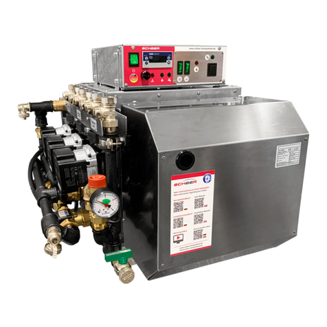
Scheer MH Series User manual

user guide
MH-Series water heater
MH 10/17
MH 15/23
MH 30/40
MH 20 micro L
MH 10 micro

2
Dear customer,
thank you for choosing to install our MH-series into your vehicle.
With your purchase of the MH-series, you ensured for yourself, to have a heating system with currently the highest tech-
nological standard and lowest fuel consumption.
The innovative and award-winning technology of our products with the “Blue Eciency®” burner, will
provide you with an especially user and maintenance friendly operation. This system will give you comfort and highly
reduced emissions.
The successfully proven blue-burner-system in “Duo-Block“ building technique, as well as the simple operation over the
boiler control eld, are very ecient and environmentally friendly.
We hope that, how to use the heating system and all of its functions are explained to you to your full satisfaction, by
the installing auto shop or service station. With this user guide we would like to give you more information how to use it
properly.
Please contact us for any questions or further information you need.
Your SCHEER-team
introduction
SCHEER
Heizsysteme & Produktionstechnik GmbH
Chausseestr. 16
D-25797 Wöhrden
Tel.: +49 (0) 4839 905-0
Fax: + 49 (0) 4839 453
info@scheer-heizsysteme.de
www.scheer-heizsysteme.de
Note:
Always carefully follow SCHEER installation and repair instruction and heed all WARNINGS.
The heaters of the MH-series are type-tested and approved in accordance with the ECE Directives ECE R22 and ECE R10.
The unit must be installed in accordance with the enclosed installation instructions.
SCHEER accepts no liability for defects and damage resulting from installation by untrained personnel.

3
2
3
4
4
5
6
7
7
7
8
9
Introduction
Table of contents
Warnings and Safety Precautions (Explanation)
Warning and safety instructions
General operating instructions
Control box A
Control box M
Heating controller
Setting the unit function
Fault lights
Room unit for control box (optional)
table of contents

4
warning and safety signs (denition)
classication of the signal word according to ANSI Z535.4
signal word identication of hazard
NOTICE [this header is] preferred to address practices not related to personal injury. Used for property
damage.
CAUTION! Indicate[s] a hazardous situation which, if not avoided, could result in minor or moderate injury.
WARNING! Indicate[s] a hazardous situation which, if not avoided, could result in death or serious injury.
DANGER! Indicate[s] a hazardous situation which, if not avoided, will result in death or serious injury.
The following table explains the used colors, words and their meaning used in this manual.
warning and safety signs
DANGER! Death or serious injury due to improper installation or repair.
Improper installation or improper repair can cause a re or the leakage of deadly carbon monoxide leading to
serious injury or death.
• The person to install and repair the heating system must have completed a SCHEER training course.
• Always follow all installation and repair instruction.
• Heed all warning and safety signs.
• All required technical documentations, tools, and equipment must be available for installation and repair.
DANGER! Death or serious injury by re!
The use of the heater in areas with ammable materials can cause an explosion or a re. This can cause serious
injury or death.
• Never use the heater at fuel/gas stations or close to tanks with ammable content.
• Never use the heater at places with ammable vapors or combustible dust. (e. g. close to: fuel, cole, wood dust, or
grain storages)
• Never use the heater close to ammable materials. (e. g. close to: dry gras and leafs, cardboard, paper etc.)
DANGER! Death or serious injury by suocation!
The use of the heater in non-ventilated areas can result in serious injury or death.
• Never use the heater in closed rooms (e.g. garage, storage).
• Never use the heater in closed rooms with a timer or tele start. (e.g. garage, storage)
(see also next page)

5
NOTICE: Risk of malfunction or damage by heat exposure!
Surrounding temperatures higher than 110°C (230°F) can cause damage to the electronics.
• Never use or store the heater in areas of 110°C (230°F) or more.
NOTICE: Risk of malfunction or damage by frost!
If the water freezes in the heat circuit or fresh water supply system, it can cause damage to the equipment.
• Make sure to have at least 20% of antifreeze mixed into the heating circuit water.
• In risk of frost, drain the fresh water out of a heat system with plate heat exchanger.
Note: SCHEER cannot be held liable for:
• Defects and damage resulting from installation by untrained personnel.
• Non-observance of the installation instructions and the information contained therein.
• Failure to observe the warning and safety instructions.
• Installation of non-original spare parts.
general operating instructions
Please note the following general operating instructions after installing and during the use of the MH-heating
system:
• The heating system must be turned o before you get fuel at gas stations.
• The year of the rst start-up must be permanently marked on the identication plate.
• Make sure all existing shut-o valves of the fuel return line are open before using the system.
• Check the openings of the combustion air supply and exhaust pipe for dirt and clean if necessary.
• After replacing the vehicles cooling uid
make sure to
bleed the system
of air thoroughly.
Add cooling uid
when
needed.
• After replacing the heating circuit water (solution) make sure to bleed the system of air thoroughly. Add solution
when needed. (at least 20% antifreeze)
• Make sure to use the fuel and operation power indicated on the identication plate.
• In case of heavy smoke development, unusual burner noise, or smell of fuel, disable the heating system by remo-
ving its fuse. Operate the system only, after a technical inspection by a SHEER trained person.
• Turn on the heating system at least once a month for 10 min.
• The heating system must be checked by a SCHEER trained person, before each heating season.
• Liability claims can only be asserted, if the claimant can prove adherence to the installation, maintenance, and safety
instructions.
warning and safety signs

6
general operating instructions
Disposal of old equipment
At the end of its service life the device has to be disposed of in accordance with national regulations. It is recommended
to contact a company specializing in waste disposal or contacting the disposal department of your commune.
WARNING:
To prevent misuse and associated hazards, render your old appliance unusable before disposing of it. To
do this, disconnect the appliance from the mains supply and remove the mains connection cable from
the appliance. To dispose of the appliance, follow the regulations in force in your country and municipa-
lity.
The MH-heating systems are approved for the use of „diesel“ and „heating oil“. Any other type of fuel for
operating have to be in advance approved by the manufacturer SCHEER. The heaters are designed for 230 Volts.
The connection in the vehicle has to be fed from the battery of the vehicle via an inverter approved in road trac within the
scope of the ECE Regulation. Alternatively, the heater can also be done via a 230V direct supply (for example: direct supply of
the campsite).
WARNUNG: Danger from electric current!
The appliance may only be operated at properly installed individual sockets with protective contact.
Do not pull the mains connection cable out of the socket by the cable, always grasp the housing of the mains plug.
control box A for MH-Series
STL* release
button (STB*)
STL indicator
Domestic hot water heating
(optional)
Radiators (optional)
Underoor heating (optional)
Tank-Control
(if the tank is empty - lights up red)
(optional)
Tank-Control
* Safety temperature limiter
Burner demand
Item No.
control box A 0754481

7
control box M
• Use the and keys and to set the value in the specied value range.
• Conrm settings with P
Parameter Meaning Value range
from ...factory...to
SP Setpoint
This value is used for regulation
50 ...0.0 ... 80
control box MH micro
Electric
heating Activate / lock burner
Burner request active
Electric
heating
active
On / O
switch
Heating controller
Symbol for heat request
Actual value boiler temperature
Item No.
controlbox M
(single stage) 0754486
Polarity luminaire
STB lamp

8
MH: warning lamp STL MH Micro: warning lamp STL
NOTICE
Polarity: This light must be permanently lit green. Otherwise, connect with correct polarity.
Reverse polarity protection prevents the wrong polarity (reversal of polarity) in the DC power sup-
ply (reversal of negative and positive poles) or AC power supply (reversal of outer conductor and
neutral conductor) of a device and can thus minimise possible damage.
polarity (reversed polarity) and can thus minimise possible damage.
NOTICE
warning lamp: safety-temperature-limiter (STL)
If the lamp lights, the (STL) was triggered by a too high operating temperature.
• Let the heating system cool down.
• Push the reset (STL) button all the way in. (followed by a click sound)
• The heating system is ready to start again.
In case the (STL) is triggered again, let the system be repaired by a SCHEER trained person.
control box warning lamp
NOTICE
warning lamp: burner
If the lamp lights, it was triggered by a malfunction of the burner.
• Press and hold the burner suppressor button briey for about 1 second, not longer than 2 seconds.
• The warning lamp of the burner will turn o and the burner is reset.
If the burner should switch to malfunction twice, please have a repair carried out by your specialist company.
MH Suppression button on the control unit
MH Micro Burner fault light with reset button (additional reset button on the control unit)
NOTICE
Repeatedly running the unit empty of fuel can cause damage to the unit!
If the heater is operated without fuel, damage (e.g. to the oil nozzle) may occur
NOTICE
Other mains modules and control boxes may only be used in consultation with the manufacturer SCHEER.

9
Room thermostat - WLAN-capable (optional)
Please read these operating instructions for all information on the installation and operation of your thermo-
stat. Make sure that the thermostat is installed and connected by a professionally qualied person and that it
complies with all regional regulations.
In the box you will nd:
1x thermostat
1x QC certicate
2x screws
1x ext. sensor (2.5 metres)
About your thermostat
The room thermostat is suitable for use in commercial, industrial, civil and domestic applications, such as the
control of oor or radiator heating circuits
Functions
• Networking through Modbus and WLAN
• 0.5°C accuracy
• Short-term memory in case of power failure
• 5+1+1 weekly programme with 6 periods comprehensive time programme
• Controllable by Amazon Echo, Google Home, Tmall Genie
dimensions
86
86
39
2613 26
26
Room thermostat art. no.
incl. WLAN connection 0170106

10
Before installing the thermostat
1. Read this instruction manual carefully. If you do not follow these instructions, you may damage the product
or cause dangerous situations.
2. Make sure that the thermostat is suitable for the intended use.
3. The installer must be trained in the connection of electrical products (especially 230V) and have sucient
experience in connecting electrical equipment.
4. After installation, check for correct operation according to these instructions.
CAUTION:
Risk of electric shock or damage to tools and
product during connection. There is a possibility
of persons experiencing an electric shock or a
short circuit causing damage to equipment or
the product.
Before installation, make sure that the power
supply and all other connection lines are de-
energised!
Technical Data
Power Supply 95~240VAC, 50~60Hz Timing error <1%
Current Load max 5A Shell Material PC + ABS (re proof)
Sensor NTC3950, 10k Installation Box 86x86mm square/ Europ.
60mm round
Accuracy ±0,5°C Wire Terminals 2*1,5mm² / 1x2,5mm²
Set Temp. Range: 5-35°C Protection Class IP20
Display Temp. Range 5~99°C Storage Temp -5~45°C
Ambient Temp.: 0~45°C Power Consumption <1,5W
Ambient Humidity: 5~95% RH (not condensing)

11
Your thermostat is suitable for installation inside a standard 86 mm junction box or a European 60 mm junction box.
Step 1
De-energise all connecting cables (Fig. 1).
Fig. 1
Step 2
Remove the mounting plate by rotating the LCD part (Fig. 2).
Fig. 2
Step 3
Connect the power supply to the corresponding terminals of the thermostat
(L - phase; N - neutral); connect the switching contacts to terminals 1 and 2. (Fig. 3)
Fig. 3
Step 4
Fix the mounting plate to the wall using the screws supplied (Fig. 4).
Fig. 4
Step 5
Fix the LCD part of the thermostat to the xing plate by rotating it.
Installation complete.
Fig. 5 Fig. 6
Installation

12
Homescreen quick reference
day roomtemperature
heating period
AM / PM
time
downuppowerclock
manual mode
time mode
heating active
ext. sensor active
set temperature
room temperature
lock
operation
1. Power on/o: Press to turn the thermostat on/o.
2. Manual/ Time program mode: Touch to change between manual mode and program mode. In manual
mode, will show in the bottom left of the screen. In programmable mode, the period icon will show on
the right side.
3. Setting Temperature: In the time program mode the temperature can only be controlled by the set hea-
ting program. In the manual mode, press to set the desired temperature.
4. Adjusting/Setting the Clock: Touch the to set minute, hour and weekday (1 = Monday, 2 = Tuesday etc.)
by using the arrows. Press once more to conrm and exit.
5. Locking your Thermostat: Press and hold the for 5 seconds to lock/unlock your thermostat. In item
3 of the device parameters, you can select full lock (included).
6. Adjusting/setting the Program Schedules: When Wi-Fi connection is made, your thermostat will auto-
matically accept the program schedule made via the APP on your device (see below for detailed instruc-
tions) To set the program schedules through your thermostat (NOT via your smartphone/tablet) simply
follow the instructions as below:
Please note: Setting the programme schedule through your thermostat can only be carried out if there is
no Wi-Fi connection between your thermostat and smartphone/tablet
7. Setting / adapting the time program on the thermostat: The time program can only be set on the
device if there is no active WLAN connection and time program mode is activated. Touch to change
between manual/ time program mode. In program mode, touch and hold the icon until the weekday
schedule settings appear (1 2 3 4 5 will show along the top of the screen). Use the arrows to adjust
the„on“ time.
Press the icon and use the arrows to set the o time (2nd period).
Press the icon and use the arrows to set the temp. Repeat this process for periods 3 - 6.
Press the icon once more to enter the Saturday schedule settings (6 will show along the top of the
screen). Repeat the above process to set the periods as well as temp. as well as Sunday schedule. Press
once more to conrm and exit.
select mode

13
Default settings for program schedule
heating
periode
weekday
(Monday-Friday)
(1 2 3 4 5)
Weekend
(Saturday)
6
Weekend
(Sunday)
7
time temperature time temperatur time temperatur
period 1 06:00 AM 20°C 06:00 AM 20°C 06:00 AM 20°C
period 2 08:00 AM 15°C 08:00 AM 20°C 08:00 AM 20°C
period 3 11:30 AM 15°C 11:30 AM 20°C 11:30 AM 20°C
period 4 01:30 PM 15°C 01:30 PM 20°C 01:30 PM 20°C
period 5 05:00 PM 22°C 05:00 PM 20°C 05:00 PM 20°C
period 6 10:00 PM 15°C 10:00 PM 15°C 10:00 PM 15°C
A separate schedule may be set for weekdays (Mon - Fri) and for weekends (Sat or Sun).
Change the system settings
Turn o the device.
Press and at the same time for 5 seconds to get to the system settings. Then press to cycle through the
available settings and use to change the parameter values. All changes will be saved automatically.
code function setting an options default
1temperature
compensation
-7 bis +9°C {for internal sensor) -1
2deadzone
temperature
1-5°C 1
3button locking 00: all buttons locked exept on/o
01: all buttons locked
01
4sensor types In: Internal Sensor (to control the temp.)
Ou: External Sensor (to control the temp.)
AL: Internal/ External Sensor (Internal sensor to control the temp., exter-
nal sensor to limit the oor temp.)
AL
5min. set tempature 5-15°C 05
6max. set temperature 15-45 °C 35
7display mode 00: display of set temp. and room temp.
01: display of only set temp. 00
8low temperature protection
setting 0-10°C 00
9high temprature protection
setting 25-70°C 45
Aeconomy mode 00: non-energy saving mode
01: energy saving mode 0
Beconomy temprature 0-30°C 20
Cstandby brightness 3-99 20

14
Wi - connection
Before using your WLAN thermostat for the rst time, you must congure the WLAN connection and the settings on the
smartphone once. This enables communication between your connected devices.
Step 1: Download the„Smart Life“ APP
Fig. 1-1 Fig. 1-2 IOS Fig. 1-3 Android
For IOS devices, search for„Smart Life“ in the Apple Store, for Android devices in the Google Play Store and download it.
Alternatively, scan the corresponding QR code (Fig. 1-2).
Step 2: Create a user account
Fig. 2-1 Fig. 2-2 Fig. 2-3 Fig. 2-4
Open the„Smart Life“ app and agree to the notication that appears (Fig. 2-1). The registration screen appears (Fig. 2-2).
Press„Register“ and enter your mobile phone number or e-mail address (Fig. 2-3). You will receive a conrmation code
by e-mail or SMS and can set a password after entering the code (Fig. 2-4). This completes the registration and you can
log in.
Step 3: Establish the WLAN connection
Try connecting using EZ mode. If your router does not support this or your Wi-Fi signal is weak so you cannot connect
to the thermostat, try AP mode.
EZ-Modus
On your thermostat
Hold for eight (8) seconds. While the thermostat is switched o the backlight will be on and the icon will ash
one time per second.

15
In the App
Fig. 3-1.1 Fig. 3-1.2 Fig. 3-2 Fig. 3-3 Fig. 3-4
Press „Add device“ on the app‘s home screen (Fig. 3-1.1). Select „Small household appliances“ on the left and scroll
down so that you can select „Thermostat (Wi-Fi)“ (Fig. 3-1.2). In the next step, select your WLAN and enter the network
key. Conrm with „Next“ (Fig. 3-2). In the next step, make sure that the WLAN symbol on the thermostat is ashing
(when the thermostat is switched o). Then tick the item „Conrm that the display ashes quickly“ and conrm with
„Next“ (Fig. 3-3). The thermostat is then automatically connected to the WLAN and added to your user account (Fig.
3-4). The thermostat is now permanently connected to your account so that you can also access your thermostat out-
side the WLAN with your smartphone. Repeat the process for further devices.
AP-Modus
On you thermostat
With the device turned o, press for 8 seconds. The backlight turns on and the icon ashes once per second.
Press and hold again for 8 seconds. The symbol ashes every 3 seconds.
In the app
Press „Add device“ on the app‘s home screen (Fig. 3-1.1). Select „Small household appliances“ on the left and scroll
down so that you can select „Thermostat (Wi-Fi)“ (Fig. 3-1.2). In the next step, select your WLAN and enter the network
key. Conrm with „Next“ (Fig. 3-2). Switch from EZ mode to AP mode in the top right corner, the thermostat will create
a WLAN hotspot. In the next step, make sure that the WLAN symbol on the thermostat is ashing (when the thermos-
tat is switched o). Then tick the item „Conrm that the display ashes quickly“ and conrm with „Next“ (Fig. 3-3). The
thermostat creates a WLAN hotspot to which you must connect your smartphone. To do this, go to „Connect now“
(Fig. 4-2). You will be directed to your system settings, select the WLAN network „SmartLife-XXXX“ there and connect
your smartphone to it. Return to the SmartLife App, where the thermostat will be connected automatically. Once the
connection has been successfully established, the thermostat will exit the hotspot and your smartphone will reconnect
to the local Wi-Fi network.
Abb. 4-1 Abb. 4-2

16
Programming the termostat via APP
Fig. 5-1 Fig. 5-2 Fig. 5-3 Fig. 5-4
When your room thermostat has been successfully set up, it is displayed on the start screen of the app (Fig. 5-1). The
round button is used to switch your thermostat on and o. Click on the three dots in the upper right corner to start
programming.
• On/o switch : switches the unit on and o again.
• Locking / unlocking the buttons : when the button is green, the screen is locked, when the symbol is grey, it is
unlocked.
• Economy mode : in this mode, the temperature 20°C is maintained. This temperature cannot be changed.
• Manual mode : In this mode, the room temperature can be set manually (time programme deactivated)
• Time programme mode: In this mode, the room temperature can be set manually (time programme deactivated).
• The yellow slider can be used to adjust the room temperature in manual mode. The current room temperature is
displayed a few seconds after adjustment.
• In schedule mode, click on the schedule setting (at the bottom of the page) to go to the schedule page (see Fig.
5-2), where you can simply click on the working days (Mon. - Fri.) and then on the time/temp to adjust it to your
preferred schedule.
• You can set time and temp. for 6 periods (Fig. 5-3).
• Repeat the steps after clicking on the„Weekend (Saturday - Sunday)“ settings at the top of the page.
• Once your schedule has been set, click SAVE and the app will send the time programme to the thermostat and
report that the schedule has been saved.

17
Further functions and troubleshooting
Fig. 6-1 Fig. 6-2 Fig. 7-1 Fig. 7-2
If you use several room thermostats, you have the option in the app to combine these room thermostats into a group so
that you can set the temperature of all three devices simultaneously.
To do this, press the three dots in the top right corner of the app (Fig. 5-2) and then„Create group“ (Fig. 6-1). Then select
all the desired units and conrm.
In addition to creating groups, you can also change the device name, share your device and obtain information about
your device in the menu.
How do I release a unit?
Option 1: Follow the steps in the previous section, but press„Share Device“ in the menu.
Option 2: On the app home page, click on your prole at the bottom right (Fig. 6-2). Select Device Sharing and add the
account you want to share a device with. You can then see which account you have shared with and which device you
have shared. You can share as many devices as you want.
How do I connect my device to Amazon Echo or Google Home?
Go to the menu and press Amazon Echo or Google Home. Follow the instructions on the screen.
Simple troubleshooting
Nr. Occurring error Troubleshooting
1The power supply is switched on, but the indi-
cator is not illuminated
Check whether the connections between the LCD panel and the thermo-
stat body have come loose
2The display lights up but shows nothing Use a new LCD panel or new Power Unit Box to replace the old one.
3The measured room temperature deviates from
the actual temperature
Perform the temperature calibration in item 1 of the upper power range
options

12/2021 R1
SCHEER
Heizsysteme & Produktionstechnik GmbH
Chausseestr. 16
D-25797 Wöhrden
Tel.: + 49 (0) 4839 / 905-0
Fax.: +49 (0) 4839 / 453
info@scheer-heizsysteme.de
www.scheer-heizsysteme.de
MH-Series
water heater
user guide
Heizsysteme der Extraklasse
Other manuals for MH Series
2
This manual suits for next models
5
Table of contents
Other Scheer Water Heater manuals
Popular Water Heater manuals by other brands

Webasto
Webasto Thermo Top E installation instructions

Airxcel
Airxcel SW5EA Operating, installation and service manual

GE
GE 50T06AAG Energy guide

Energie
Energie ECO 200esm Installation Instructions and Use & Care Guide

Helios
Helios AIR1 Series Installation and operating instructions

Ariston
Ariston BOOSTER user guide