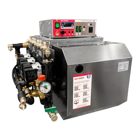
Scheer MA 50 User manual

revised 01/2018 - V 5.0
innovative heat systems
user‘s instructions
MA-water heater
MA 50
MA 70
MA 50/70

www.scheer-heizsysteme.de
MA-SERIES
Dear customer,
thank you for choosing to install our MA-series into your vehicle.
With your purchase of the MA-series, you ensured for yourself, to have a heating system with currently the
highest technological standard and lowest fuel consumption.
The innovative and award-winning technology of our products with the Blue Eciency® burner, will
provide you with an especially user and maintenance friendly operation. This system will give you comfort
and highly reduced emissions.
The successfully proven blue-burner-system in “Duo-Block“ building technique, as well as the simple
operation over the boiler control eld, are very ecient and environmentally friendly.
We hope that, how to use the heating system and all of its functions are explained to you to your full
satisfaction, by the installing auto shop or service station. With this user‘s instruction we would like to give
you more information how to use it properly.
Please contact us for any questions or further information you need.
Your SCHEER-team
introduction
SCHEER
Heizsysteme & Produktionstechnik GmbH
Chausseestr. 12 - 16
D-25797 Wöhrden
Germany
Tel.: +49 (0) 4839 905-0
Fax: + 49 (0) 4839 453
info@scheer-heizsysteme.de
www.scheer-heizsysteme.de
Note:
Always carefully follow SCHEER installation and repair instruction and heed all WARNINGS.
The heaters of the MH-series are type-tested and approved in accordance with the ECE Directives ECE R22 and
ECE R10.
SCHEER rejects any liability for problems and damage caused by the system installed by untrained
personnel.
2

www.scheer-heizsysteme.de
MA-SERIES
table of contents
introduction
table of contents
warning and safety signs (denition)
warning and safety signs
general operating instructions
control box C
2
3
4
5
5
7
3

www.scheer-heizsysteme.de
MA-SERIES
warning and safety signs (denition)
The following table explains the used colors, words and their meaning used in this manual.
warning and safety signs
classication of the signal word according to ANSI Z535.4
signal word identication of hazard
NOTICE
Notice: [this header is] preferred to address practices
not related to personal injury. Used for property
damage.
CAUTION! Caution: Indicate[s] a hazardous situation which, if not
avoided, could result in minor or moderate injury.
WARNING! Warning: Indicate[s] a hazardous situation which, if not
avoided, could result in death or serious injury.
DANGER! Danger: Indicate[s] a hazardous situation which, if not
avoided, will result in death or serious injury.
The use of the heater in areas with ammable materials can cause an explosion or a re. This can
cause serious injury or death.
• Never use the heater at fuel/gas stations or close to tanks with ammable content.
• Never use the heater at places with ammable vapors or combustible dust.
(e. g. close to: fuel, cole, wood dust, or grain storages)
• Never use the heater close to ammable materials.
(e. g. close to: dry gras and leafs, cardboard, paper etc.)
DANGER! Death or serious injury by re!
The use of the heater in non-ventilated areas can result in serious injury or death.
• Never use the heater in closed rooms (e.g. garage, storage).
• Never use the heater in closed rooms with a timer or tele start. (e.g. garage, storage)
DANGER! Death or serious injury by suocation!
(see also next page)
Improper installation or improper repair can cause a re or the leakage of deadly carbon monoxide
leading to serious injury or death.
• The person to install and repair the heating system must have completed a SCHEER training course.
• Always follow all installation and repair instruction.
• Heed all warning and safety signs.
• All required technical documentations, tools, and equipment must be available for installation and
repair.
DANGER! Death or serious injury due to improper installation or repair.
4

www.scheer-heizsysteme.de
MA-SERIES
warning and safety signs
general operating instructions
Please note the following general operating instructions after installing and during the use of the
MH-heating system:
• The heating system must be turned o before you get fuel at gas stations.
• The year of the rst start-up must be permanently marked on the identication plate.
• Make sure all existing shut-o valves of the fuel return line are open before using the system.
• Check the openings of the combustion air supply and exhaust pipe for dirt and clean if necessary.
• After replacing the vehicles cooling uid make sure to bleed the system of air thoroughly. Add cooling
uid when needed.
• After replacing the heating circuit water (solution) make sure to bleed the system of air thoroughly.
Add solution when needed. (at least 20% antifreeze)
• Make sure to use the fuel and operation power indicated on the identication plate.
• In case of heavy smoke development, unusual burner noise, or smell of fuel, disable the heating
system by removing its fuse. Operate the system only, after a technical inspection by a SHEER trained
person.
• Turn on the heating system at least once a month for 10 min..
• The heating system must be checked by a SHEER trained person, before each heating season.
• Liability claims can only be asserted, if the claimant can prove adherence to the installation,
maintenance, and safety instructions.
•
Surrounding temperatures higher than 110°C (230°F) can cause damage to the electronics.
• Never use or store the heater in areas of 110°C (230°F) or more.
NOTICE Risk of malfunction or damage by heat exposure!
•
If the water freezes in the heat circuit or fresh water supply system, it can cause damage to the
equipment.
• Make sure to have at least 20% of antifreeze mixed into the heating circuit water.
• In risk of frost, drain the fresh water out of a heat system with plate heat exchanger.
NOTICE Risk of malfunction or damage by frost!
Note: SCHEER cannot be held liable for:
• Defects and damage, which are due to installation or repair by unauthorized and untrained persons.
• Failure to comply with the instructions and the warning/safety signs.
• The installation of non-original spare parts.
5

www.scheer-heizsysteme.de
MA-SERIES
Disposal of old equipment
At the end of its service life the device has to be disposed of in accordance with national regulations.
It is recommended to contact a company specializing in waste disposal or contacting the disposal
department of your commune.
WARNING!
To prevent misuse and the associated dangers, make your old equipment unusable before disposal. There-
for disconnect the device from the power supply and remove the power cable from the device. To dispose
the device, observe the regulations applicable in your country and in your commune.
WARNING!
Danger due to electrical current!
The device may only be operated on properly installed single sockets with protective contact.
Do not disconnect the mains cable from socket by pulling the cable, always touch the housing of
the mains plug.
The MA-heating systems are approved for the use of „diesel“ and „heating oil“. Any other type of fuel for
operating have to be in advance approved by the manufacturer SCHEER. The heaters are designed for 230 Volts.
The connection in the vehicle has to be fed from the battery of the vehicle via an inverter approved in road traf-
c within the scope of the ECE Regulation. Alternatively, the heater can also be done via a 230V direct supply
(for example: direct supply of the campsite).
general operating instructions
6

www.scheer-heizsysteme.de
MA-SERIES
control box C
The control panel is divided into three areas:
Status displays, operating program sequence and service area.
status display
In the status displays, all lights should light up continuously in the operating state.
The polarity lights up continuously if the electrical supply is connected in the correct phase. If the polarity is not
correctly applied, operation is not negatively inuenced by the electrical connection. Nevertheless, service or
monitoring tasks cannot be carried out properly if the connection is incorrect.
The water level indicator lights up continuiously if there is sucient water in the boiler. If the operating indi-
cator does not light up, there is insucient water in the system! If the boiler is red without water, it will be
damaged. Check the water level, please. If there is suvvicient water in the system, contact SCHEER to be able to
bridge the water level switch using emergency operation.
pump control
The pump control inducates that the heating water circulates in the boiler via the heating curcuit pump and
the heat can be gradually transferred into the building after uniform heating of the boiler via the mixer.
operating program sequence
The display of the operating program sequence shows the user the step-by-step progress of operation.
burner requirement
First of all, the burner requirement shows that heat is required and the burner should now start. For this purpo-
se, som sequences are connectet upstream.
oil ventilation
The oil venting is activated for 60 seconds.
oil preheater
The oil preheater is then switched on. Depending on the temperature of the fuel oil, preheating can take die-
rent lenghths of time. In case of very cold fuel oil and the rst operation of the burner (after a long interruption)
this can take up to two minutes. Only then does burner operation start when the boiler is dired and the burner
operating light is acitvated.
boiler protection acitvated
With boiler protection acitvated, it is indicated that a permanent minimum heat level in the boiler return ow is
noch reached an thus recurring condensation does not occur in the boiler body.
7

www.scheer-heizsysteme.de
MA-SERIES
control box C
service area
The service area displays are intended for service work.
Solenoid valve II in continuous operation
The display of the solenoid valve II shows that it is activated in continuous operation. Activation is the user‘s
own responsibility and requires the separation of the corresponding lead seal and switch assignment after
consultation with SCHEER.
oil ventilation
If the burner is operated without oil venting, this can be bridged for servicing. This is the user‘s own responsibi-
lity and requires the separation of the corresponding lead seal and switch assignment after consultation with
SCHEER.
Emergency operation bridging water level monitor
As an emergency operation, it is entended that the machine can also be operated if the water level monitor is
defective and there is sucient water in the boiler. Only in this case is it possible to bridge the water level moni-
tor until it is repaired. This is the user‘s own responsibility and requires the separation of the corresponding lead
and switching of the switch after consultation with SCHEER.
Emergency operation without controller
Emergency operation without controller can be carried out at the user‘s own responsibility and requires discon-
nection of the corresponding lead seal and switching of the switch after consultation with SCHEER.
Setting the instrument function
• Use the keys and to set the value in the specied range of values.
• Conrm settings with P
parameter signicance range of values
from ...factory-made...to
SP target value
This value is controlled by
50 ...0.0 ... 80
8

www.scheer-heizsysteme.de
MA-SERIES
power module
warning lamp: safety-temperature-limiter (STL)
If the lamp lights, the (STL) was triggered by a too high operating temperature.
• Let the heating system cool down.
• Push the reset (STL) button in. (followed by a click sound)
• The heating system is ready to start again.
In case the (STL) is triggered again, let the system be repaired by a SHEER trained person.
warning lamp: burner
If the lamp lights, it was triggered by a malfunction of the burner.
• Push the burner reset button at least for one second in.
• The warning lamp of the burner will turn o and the burner is reset.
In case the warning lamp of the burner is triggered again, let the system be repaired by a SHEER trained person.
warning lamp
on/o
switch
fuse holder
reset safety-temperature-limiter (STL) button
warning lamp safety-temperature-limiter (STL)
warning lamp burner
reset burner button
power on
using the on/o switch.
remote control
room controller (optional)
hybrid-heating
with additional electrical heater (optional)
power o
using the on/o switch.
altitude adjustment
standard equipment
vehicles with hazardous material (ADR) permis-
sion
manual EMERGENCY OFF switch for the whole
heating system.
power module
9

www.scheer-heizsysteme.de
MA-SERIES
4
1 2
3
5 6 7 8 9
1 hot fresh water selection 6 navigation and setting knob
2 space heating selection 7 conrm setting
3 display information 8 manual operation
4 service socket (BSB) 9 chimney sweep function
5 exit settings (for emission test)
display
operator unit
Reference of signs and symbols:
overview
1 2
3
4 5 6 7 8 9
(entfällt)
boiler controller C
Heizen auf Komfortsollwert Ferienfunktion aktiv
Heizen auf Reduziertsollwert Bezug auf Heizkreis
Heizen auf Frostschutzsollwert Wartung / Sonderfunktionen
Kühlen auf Kühlsollwert Fehlermeldungen
Laufender Prozess – bitte warten Infoebene aktiviert
Batterie wechseln Programmierung aktiviert
Brenner in Betrieb (nur Öl-
/Gaskessel); Aktive Brennerstufen Heizung vorübergehend
ausgeschaltet
ECO Funktion aktiv
Verdichter in Betrieb (nur WP)
heating to comfort set point
heating to reduced set point
heating o, frost protection on
air condition (n.a.)
processing - please wait
change battery
burner operating
burner active
compressor operating (n.a.)
holiday function
reference to heating circuit
maintenance
special operation
error messages
info level activated
programming activated
heating temporarily turn o
ECO function active
10

www.scheer-heizsysteme.de
MA-SERIES
settings boiler controller C
Selection of space heating mode
This setting is used to switch between the dierent
operating modes. The selection made is indicated by a
bar which appears below the respective symbol.
Automatic mode
Automatic mode controls the room temperature according to
the time program.
Characteristics of automatic mode:
- Heating mode according to the time program
- Temperature set points according to the heating program
„Comfort set point“
or„Reduced set point“
- Protective functions active
- Automatic summer / winter changeover (ECO functions)
Continuous operation or
Continuous operation maintains the room temperature at the
selected operating level.
Heating to Comfort set point
Heating to Reduced set point
Characteristics of continuous operation:
- Heating mode with no time program
- Protective functions active
- Automatic summer / winter changeover (ECO functions)
and 24-hours heating limit inactive in the case of
continuous operation with Comfort set point
Protection
When using protection mode, the heating system is o, but it
remains protected against frost (frost protection temperature)
provided there is no power failure.
Characteristics of Protection:
- Heating o
- Temperature according to frost protection
- Protective functions active
- Automatic summer / winter changeover (ECO functions)
and automatic 24-hours heating limit active
Selecting the DHW heating mode
The button is used to switch DHW heating mode on and o.
The selection made is indicated by a bar which appears
below the respective symbol.
DHW heating mode
- On: The DHW is heated according to the selected
switching program.
- O: No DHW heating, but the protective function is active.
DHW push
Triggering is eected by keeping the DHW operating
mode button on the operator or room unit depressed
for at least 3 seconds.
It can also be started when:
- The operating mode is “O“
- Operating mode changeover acts via H1 or
centrally (LPB)
- All heating circuits use the holiday function
Adjusting the room temperature set point
Turn the setting knob to increase or decrease the Comfort
set point
For the Reduced set point
- press OK,
- Select operating page “Heating circuit“ and
- adjust the “Reduced set point“
After each readjustment, wait at least 2 hours, allowing the
room temperature to adapt.
Displaying information
Various data can be displayed by pressing the info button.
Error messages
If this symbol appears, an error in the plant has occurred.
Press the info button and read further information.
Maintenance or special operation
If this symbol appears, a maintenance alarm is delivered or
the plant has changed to special mode. Press the info
button and read further information.
Manual operation
When manual operation is active, the relays are no longer
energized and de-energized according to the control state,
but are set to a predened manual operation state
depending on their function. The burner relay energized in
manual control can be de-energized by the electronic
temperature controller (TR). After manual control has been
activated, a change to the basic display must be made.
There, the maintenance / special mode symbol
appears. Press the info button to switch to info display
“Manual mode“, where the set point can be adjusted.
Chimney sweep function
The chimney sweep function is activated by a short press
(maximum 3 seconds) on the chimney sweep button. This
function produces the operating state required to make
emission measurements (ue gas).
11

www.scheer-heizsysteme.de
MA-SERIES
programming boiler controller C
Programming
Settings that cannot be made directly with the operating ele-
ments require programming. For this purpose, the individual
settings are structured in the form of operating pages
and operating lines, thus forming functional groups of settings.
The following example shows how to set the time of day and the
date.
Example: “Setting the time of day“
- Press ESC to go one step back at a time, adjusted values on
the previous page are not memorized.
- If no setting is made for 8 minutes, the display returns to
the default display.
- Depending on the type of controller, some operating lines
may be hidden.
display pages
Heating curve slope
As the heating curve slope is raised, the ow temperature
increases the quicker the lower the outside temperature or,
in other words, if the room temperature is not correct at low
outside temperatures but correct at higher outside tempera-
tures, the heating curve slope requires readjustment.
Increase adjustment: Raises the ow temperature,
especially when outside
temperatures are low.
Decrease adjustment: Lowers the ow temperature,
especially when outside
temperatures are low.
The programmed heating curve is based on a room set point
of 20 °C. If the room set point is adjusted, the heating curve
automatically adapts to the new value.
instructions
This is the default display. (If the
default display does not show,
press the ESC button until it shows.)
Press the OK button to select the
next operating page.
At the bottom of this operating
page are two operating lines. One
of it is highlighted. Turn the setting
knob until the operating line„Time
of day and date“ is highlighted.
Press OK.
At the bottom of this page, the last
operating line shows“Hours / Min-
utes “. Press OK .
The display shows the hours
ashing. Turn the setting knob to
the current hours. Press OK .
The display shows the minutes
ashing. Turn the setting knob to
the current minutes. Press OK .
The settings are saved when the dis-
play stops ashing. To return to the
default display press the ESC button
until it shows.
12

www.scheer-heizsysteme.de
MA-SERIES
programming spreadsheet boiler controller C
Operating line
User level
Function
Default value
Min
Max
Unit
Time of day and date
1 E Hours/minutes - 00:00 23:59 hh:mm
2 E Day/month - 01.01 31.12 tt.mm
3 E Year - 2004 2099 jjjj
Operator section
20 E Language German Eng., French, Ital., Dutch, Esp., Port., Dansk, Suomi, Svenska
21 E Units °C, bar °F, PSI
Time prog heating circuit 1
500 E Preselection
Mo-Su Mo-Fr Sa-Su Mo Tu We Th Fr Sa Su Mo-Su -
501 E 1st phase on 06:00 00:00 24:00:00 hh:mm
502 E 1st phase o 22:00 00:00 24:00:00 hh:mm
503 E 2nd phase on 24:00 00:00 24:00:00 hh:mm
504 E 2nd phase o 24:00 00:00 24:00:00 hh:mm
505 E 3rd phase on 24:00 00:00 24:00:00 hh:mm
506 E 3rd phase o 24:00 00:00 24:00:00 hh:mm
516 E Standard values No Yes No -
Time prog heating circuit 2
520 ... 536 E like time prog heating circuit 1
Time program 3 / HCP
540 ... 556 E like time prog heating circuit 1
Time program 4 / DHW
560 ... 576 E like time prog heating circuit 1
Time program 5
600 ... 616 E like time prog heating circuit 1
Holidays heating circuit 1
641 E Preselection Period 1...8 Period 1 -
642 E Start -.- 01. 01 31. 12 tt.mm
643 E End -.- 01. 01 31. 12 tt.mm
648 E operating level Frost protection Reduced frost protection -
Holidays heating circuit 2
651 ... 658 E like holidays heating circuit 1
Holidays heating circuit P
661 ... 668 E like holidays heating circuit 1
Heating circuit 1
710 E Comfort cooling set point 20.0 Operating line 712 Operating line 716 °C
712 E Reduced set point 16 Operating line 714 Operating line 710 °C
714 E Frost protection set point 10.0 4 Operating line 712 °C
720 E Heating curve slope 1.50 0.10 4.00 -
730 E Summer/winter heating limit 18 --- / 8 30 °C
Heating circuit 2
1010 ... 1030 E like heating circuit 1
Heating circuit P
1310 ... 1330 E like heating circuit 1
DHW
1610 E Nominal set point 55 40 65 °C
13

www.scheer-heizsysteme.de
MA-SERIES
Default display:
Actual room temperature
2
1
3 4 5
22.5 °C
overview
1 control knob
2 display
3 navigation bar
4 status bar
5 work area
operation
The display is structured with a navigation bar, status bar, and work area.
The overview page with navigation bar is displayed when you activate the device. The navigation bar provides
for direct access to the main functions.
If you want to query information on heating, ventilation, and hot fresh water, turn the control knob and select
the desired topic from navigation.
To adjust values, press the knob after selecting the desired main function. Then select the value you want to
adjust in the work area.
Operating objects may have three display states:
Time-out functions:
editing time-out: 5 seconds A changed setting reverts to the original state if not conrmed within
this period.
locking time-out: 1 minute Certain plant states are displayed in the foreground, e.g. special mode
page. However, users are still able to go to any page and set values.
The foreground page returns after this period without operator
intervention.
operating time-out: 8 minutes After this period without operation, display automatically returns to the
start page.
room controller for boiler controller C(optional)
room controller for boiler controller C (optional)
14

www.scheer-heizsysteme.de
MA-SERIES
navigating and setting
navigation topics
room controller for boiler controller C(optional)
15

www.scheer-heizsysteme.de
MA-SERIES
energy saving room controller for boiler controller C (optional)
16

www.scheer-heizsysteme.de
MA-SERIES
system consumption settings room controller for boiler controller C (optional)
17

www.scheer-heizsysteme.de
SCHEER
Heizsysteme & Produktionstechnik GmbH
Chausseestr. 12 - 16
D-25797 Wöhrden
Germany
Tel.: + 49 (0) 4839 / 905-0
Fax.: +49 (0) 4839 / 453
info@scheer-heizsysteme.de
www.scheer-heizsysteme.de
best in convenience and comfort
- MA-series -
Other manuals for MA 50
1
This manual suits for next models
2
Table of contents
Other Scheer Water Heater manuals
Popular Water Heater manuals by other brands

Brigade
Brigade BR11055 owner's manual

Kospel
Kospel KDE Assembly and operating instructions

Modine Manufacturing
Modine Manufacturing HSB Series Installation and service manual

Rheem
Rheem 260 Litre Installation and owner's guide

Rheem
Rheem PRO415TM Specification sheet

Bosch
Bosch GWI-N Series Training and Service Information