Schiller BOB-CAT PROCAT 5000 User manual

OPERATOR'S / PARTS MANUAL
MAN 4177483
Rev. C 10-2019
www.bobcatturf.com
9995010
BC PROCAT 5000 B&S VAN 24HP W/48 SIDE DISCHARGE TA
(S/N 0142 thru Present)
9995011
BC PROCAT 5000 B&S VAN 24HP W/52 SIDE DISCHARGE TA
(S/N 0196 thru Present)
9995012
BC PROCAT 5000 B&S VAN 26HP W/61 SIDE DISCHARGE TA
(S/N 0173 thru Present)

ADVERTENCIA WARNING
The engine exhaust from this product
contains chemicals known to the State
of California to cause cancer, birth
defects or other reproductive harm.
El estado de California hace saber
que los gases de escape de este
producto contienen productos quÍmi-
cos que producen cáncer, defectos
de nacimiento y otros daños en el
proceso de reproducción humana.
CALIFORNIA PROPOSITION 65
IMPORTANT!
It is a violation of California Public Resource Code Section 4442 or 4443 to use
or operate the engine on any forest-covered, brush-covered or grass-covered
land unless the engine is equipped with a spark arrestor, as dened in Sec-
tion 4442, maintained in effective working order or the engine is constructed,
equipped, and maintained for the prevention of re.
To acquire a spark arrestor for your unit, see your Engine Service Dealer.
Please refer to the engine manufacturer's information included with the ma-
chine.
Labeled power ratings are supplied by the engine manufacturer in accordance
with SAE testing and gross/net power rating standards (J1940, J1995, J1349).
WARNING: Cancer and Reproductive Harm - www. P65Warnings.com
ADVERTENCIA: Cáncer y Dãno Reproductivo - www.P65Warnings.ca.gov

1
IMPORTANT MESSAGE
Thank you for purchasing this Schiller Grounds Care, Inc. product. You have purchased a world class mowing product, one of the best
designed and built anywhere.
This machine comes with an Operation and Safety Manual and a separate Setup, Parts and Maintenance Manual. The useful life and good
service you receive from this machine depends to a large extent on how well you read and understand these manuals. Treat your machine
properly, lubricate and adjust it as instructed, and it will give you many years of reliable service.
Your safe use of this Schiller Grounds Care, Inc. product is one of our prime design objectives. Many safety features are built in, but we
also rely on your good sense and care to achieve accident-free operation. For best protection, study the manuals thoroughly. Learn the
proper operation of all controls. Observe all safety precautions. Follow all instructions and warnings completely. Do not remove or defeat
any safety features. Make sure those who operate this machine are as well informed and careful in its use as you are.
See a Schiller Grounds Care, Inc. dealer for any service or parts needed. Schiller Grounds Care, Inc. service ensures that you continue to
receive the best results possible from Schiller Grounds Care, Inc. products. You can trust Schiller Grounds Care, Inc. replacement parts
because they are manufactured with the same high precision and quality as the original parts.
Schiller Grounds Care, Inc. designs and builds its equipment to serve many years in a safe and productive manner. For longest life, use this
machine only as directed in the manuals, keep it in good repair and follow safety warnings and instructions. You’ll always be glad you did.
Schiller Grounds Care, Inc.
One Bob Cat Lane
Johnson Creek, WI 53038-0469
10-2019
TABLE OF CONTENTS ..................................................................... FIGURES.......................................................... PAGE
SAFETY.............................................................................................................................................................................2-9
LABELS.........................................................................................................................................................................10-12
CONTROLS...................................................................................................................................................................13-15
PUSHING THE MACHINE ................................................................................................................................................. 16
PRE-OPERATION CHECKLIST......................................................................................................................................... 17
OPERATION..................................................................................................................................................................18-21
MAINTENANCE CHART ................................................................................................................................................... 22
MAINTENANCE RECORD................................................................................................................................................. 23
MAINTENANCE ...........................................................................................................................................................24-31
ADJUSTMENTS............................................................................................................................................................32-39
BELT REPLACEMENT .................................................................................................................................................40-41
SPECIFICATIONS........................................................................................................................................................ 42, 43
ACCESSORIES.................................................................................................................................................................. 44
PARTS SECTION .............................................................................................................................................................. 45
ENGINE DECK ASSEMBLY............................................................... FIGURE 1 ........................................................ 46, 47
BUMPER/WRAP ................................................................................ FIGURE 2 ........................................................ 48, 49
FUEL TANKS/CONTROL PANEL....................................................... FIGURE 3 ......................................................... 50,51
TRANSAXLES/REAR WHEEL........................................................... FIGURE 4 ........................................................ 52, 53
CONTROL HANDLE ASSEMBLY....................................................... FIGURE 5 ........................................................ 54, 55
CONTROLS / BRAKE ASSEMBLY .................................................... FIGURE 6 ........................................................ 56, 57
HEIGHT OF CUT ASSEMBLY............................................................ FIGURE 7 ........................................................ 58, 59
BATTERY BOX AND GUARDS.......................................................... FIGURE 8 ........................................................ 60, 61
UPPER WIRE HARNESS .................................................................. FIGURE 9 ........................................................ 62, 63
LOWER WIRE HARNESS.................................................................. FIGURE 10 ...................................................... 64, 65
SEAT ASSEMBLY............................................................................... FIGURE 11 ...................................................... 66, 67
FOLDING ROPS ................................................................................ FIGURE 12 ...................................................... 68, 69
FOOTPLATE & CASTER ASSEMBLY................................................ FIGURE 13 ...................................................... 70, 71
48" SIDE DISCHARGE ...................................................................... FIGURE 14 ...................................................... 72, 73
52" SIDE DISCHARGE ...................................................................... FIGURE 15 ...................................................... 74, 75
61" SIDE DISCHARGE ..................................................................... FIGURE 16 ...................................................... 76, 77
CHUTE, BAFFLES & EDGES ............................................................ FIGURE 17 ...................................................... 78, 79
DECALS ............................................................................................. FIGURE 18 & 19............................................... 80-83

2
NOTICE !!!
Unauthorized modications may present extreme
safety hazards to operators and bystanders and
could also result in product damage.
Schiller Grounds Care, Inc. strongly warns against,
rejects and disclaims any modications, add-on
accessories or product alterations that are not
designed, developed,tested and approvedby Schiller
Grounds Care, Inc. Engineering Department. Any
Schiller Grounds Care, Inc. product that is altered,
modied or changed in any manner not specically
authorized after original manufacture-including the
addition of “after-market” accessories or component
parts not specically approved by Schiller grounds
Care, Inc. ,-will result in the Schiller Grounds Care,
Inc. Warranty being voided.
Any and all liability for personal injury and/or
property damage caused by any unauthorized
modications, add-on accessories or products not
approved by Schiller Grounds Care, Inc. will be
considered the responsibility of the individual(s) or
company designing and/or making such changes.
Schiller Grounds Care, Inc. will vigorously pursue
full indemnification and costs from any party
responsible for such unauthorized post-manufacture
modications and/or accessories should personal
injury and/or property damage result.
This symbol means:
ATTENTION!
BECOME ALERT!
Your safety and the safety of others is involved.
Signal word denitions:
The signal words below are used to identify levels
of hazard seriousness. These words appear in this
manual and on the safety labels attached to Schiller
Grounds Care, Inc. machines. For your safety and
the safety of others, read and follow the information
given with these signal words and/or the symbol
shown above.
DANGER indicates an imminently hazardous
situation which, if not avoided, WILL result in death
or serious injury.
WARNING indicates a potentially hazardous
situation which, if not avoided, COULD result in
death or serious injury.
CAUTION indicates a potentiallyhazardous situation
which,ifnot avoided,MAY result inminor or moderate
injury. It may also be used to alert against unsafe
practices or property damage.
CAUTION used without the safety alert symbol
indicates a potentially hazardous situation which, if
not avoided, MAY result in property damage
MODEL NUMBER: This number appears on
sales literature, technical manuals and price lists.
SERIAL NUMBER: This number appears only
on your unit. It contains the model number fol-
lowed consecutively by the serial number. Use
this number when ordering parts or seeking war-
ranty information. Located under seat plate on
Frame of unit.
SAFETY

3
SAFETY
PREPARING FOR SAFE OPERATION
Operator preparation and training
– Read, understand, and follow instructions and
warnings in the manual and on the machine,
engine, and attachments.
If you don't understand
something or itis unclear;
contact your dealer
representative for
clarication.
– Become familiar with
the safe operation of the
equipment, operator controls and safety signs.
Be prepared to stop the engine and attachments
quickly in an emergency. Do not operate or allow
another person to operate this machine if there are
any questions about safety.
– Only allow operators who are responsible, trained,
familiar with the instructions, and physically capable
to operate or service the machine. the ower is
responsible for training the users.
– Wear appropriate clothing, including long trousers
and safety goggles or safety glasses with side
shields when operating mower. Do not operate
barefoot or wearing open sandals. Long hair, loose
clothing or jewelry may get tangled in moving parts.
– If an operator or mechanic cannot read English, it is
the owner's responsibility to explain this material to
them.
This machine produced sound levels in excess of
85dBA at the operator's ear. Extended periods of
exposure can cause hearing loss.
– Wear hearing protection.
– Never allow children, unskilled or improperly trained
people to operate this equipment. Local regulations
can restrict the age of the operator.
– Only adults and mature teenagers should operate
a mower. Mature teenagers should have adult
supervision. Be sure a teenager:
1. Has read and understands the operator manual
and understands the risks involved.
2. Is sufciently mature to use caution; and
3. Is of sufcient size and weight to operate the
controls comfortably and to manage the mower
without taking risks.
– Data indicates that those operators age 60 years
and above are involved in a large percentage of
riding mower-related injuries. Those operators
should evaluate their ability to operate the riding
All rotary lawnmowers are potentially
dangerous. They can amputate hands and
feet and throw objects. Failure to follow
these safety and operating instructions
could result in serious injury or death.
WARNING
Site preparation and circumstances
– Evaluate the terrain to determine what accessories
and attachments are needed to properly and
safely perform the job. Only use accessories and
attachments approved by the manufacturer.
– Clear the area to be mowed of objects such as
rocks, toys, wire or other debris that may be picked
up or thrown by the mower.
– Be sure the area is clear of pets and people,
especially young children. Never assume they will
remain where you last saw them. Stop the machine
if any enter the area.
– Mow only in daylight or in good articial light.
– Do not mow wet grass as tires may lose traction.
mower safely enough to protect themselves and
others from injury.
– Do not carry passengers, especially small children.
They may fall off and be seriously injured.
– Keep warning labels and this operator's manual
legible and intact. Replacement labels and manuals
are available from the factory.
– Do not operate machine while under the inuence
of drugs or alcohol or any other condition of
impairment.
– The owner/user can prevent and is responsible for
accidents or injuries occurring to themselves, other
people or property.

4
SAFETY
MACHINE PREPARATION
– Do not tamper with or defeat safety devices. Keep
guards, shields and interlock safety devices in place
and in proper working condition. They are for your
protection.
– Keep all fasteners such as nuts, bolts and pins well
secured.
– Visually inspect blades, blade bolts and the cutter-
deck assembly for wear or damage. Replace worn
or damaged blades and bolts to preserve balance.
– Verify that machine and attachments, if any, are in
good operating condition.
– Grass catcher components are subject to wear,
damage and deterioration which could expose mov-
ing parts or allow objects to be thrown.
FUELING
– Gasoline can be extremely ammable; gasoline va-
pors are explosive. Use extra care when handling.
A re or explosion from gasoline can burn you or
others and /or cause property damage.
– Fill the fuel tank outdoors on level ground, in an
open area, when the engine is cold and wipe up
any spilled gasoline.
– If the engine has been running, stop the engine and
allow to cool for several minutes.
– Do not smoke, stay away from open ames or other
possible ignition sources.
– Refuel outdoors, do not refuel in indoors or in an
enclosed trailer.
– Use a funnel.
– Do not overll. Fill to the bottom of the ller neck.
The empty space allows for expansion. Overlling
may result in fuel leakage or damage to the engine
or emissions system.
– If fuel is spilled, do not attempt to start the en-
gine until the spill is cleaned up and vapors have
cleared.
– Replace caps on fuel containers and tanks securely.
– Do not operate without the entire exhaust system in
place and in good working condition.
WARNING
Under certain conditions, static electric-
ity can cause sparks during fueling and
start res or cause explosions. Flowing
fuel can generate static electricity. To prevent static
electricity sparks:
– Keep fuel containers electrically grounded.
– Do not ll containers in a vehicle or on a truck or
trailer bed with a plastic liner. Fill containers on the
ground away from the vehicle.
– When practical, remove gas powered equipment
from the truck or trailer and refuel it on the ground.
If equipment must be refueled on the truck or
trailer, refuel from a portable container rather than
a dispenser nozzle.
– If a dispenser nozzle must be used, keep the
dispenser nozzle in contact with the rim of the fuel
tank or container opening until fueling is complete.
Do not use a nozzle lock-open device
– Replace caps on fuel cans and tanks securely.
– Fill the fuel tank outdoors.
– Store fuel only in containers specically designed
for fuel.
Gasoline is harmful or fatal if swallowed.
Long-term exposure to vapors has
caused caner in laboratory animals.
– Avoid prolonged breathing of vapors.
– Keep face away from nozzle and gas tank/contain-
er opening.
– Keep away from eyes and skin.
– Do not siphon by mouth.
WARNING
WARNING

5
SAFETY
OPERATING SAFELY
Operating engine parts, especially the mufer, become
extremely hot. Sever burn can result from contact.
Debris such as grass clippings, leaves, brush, etc. can
catch re.
– Allow engine parts, especially the mufer, to cool
before touching.
– Remove accumulated debris from engine and
mufer area.
WARNING
Engine exhaust contains carbon monoxide, which is an
odorless gas that can kill you.
DO NOT run the engine indoors or in a conned
small area (such as an enclosed trailer) where carbon
monoxide fumes can collect.
Starting
– Start only according to instructions in this manual or
on the machine.
– Lightning can cause severe injury or death. If
lightning is seen or thunder is heard in the area, DO
NOT operate the machine; seek shelter.
– Be sure all drives are in neutral and parking brake
is engaged before starting engine. Use seat belts
with the roll bar in the raised and locked position.
– Do not change engine governor settings or
overspeed the engine. Operating the engine
at excessive speed can increase the hazard of
personal injury.
Operation
– Do not put hands or feet near rotating parts or
under the machine. Keep clear of the discharge
opening at all times.
– This mower was designed for use by one operator.
Keep all others away during operation.
– Do not operate when people, especially children, or
pets are in the area.
– Stop the machine if anyone enters the area.
– Do not mow in reverse unless absolutely necessary.
Always look down and behind before and while
backing.
– Slow down and use caution when making turns and
crossing roads and sidewalks.
– Stop blades when not moving.
– Stop blades when crossing surfaces other than
grass.
– Do not mow with the discharge deector raised,
removed or altered unless there is a grass
collection system or mulch kit in place and working
properly.
– Do not start the cutting blades until you are ready to
start mowing.
– Use care when approaching blind corners, shrubs,
threes, or other objects that may obscure vision.
– Do not direct discharge towards others.
– Avoid discharing material against a wall or
obstruction. Material may richochet back toward
the operator.
– Obey safety instructions. Failure to do so may
cause injury to yourself and/or others.
– Never leave a running machine unattended. Park
on level ground, turn off blades, stop engine and
remove key before leaving the operator position.
Stopping
– Park the machine on level ground. Stop the engine,
remove the key and wait for all parts to stop moving
before:
- Checking cleaning or working on the mower.
- After striking a foreign object or an abnormal
vibration occurs. Inspect and make any necessary
repairs before restarting and operating the mower.
- Before clearing blockages or unclogging.
– Park the machine on level ground. Stop the
engine, remove the key and wait for all parts to stop
moving.
- Whenever you leave the mower.
- Before refueling.
- Before emptying the grass catcher.
– Be sure all drives are in neutral and parking brake
is engaged before starting engine. Use seat belts
with the roll bar in the raised and locked position.
– Do not change engine governor settings or
overspeed the engine. Operating the engine
at excessive speed can increase the hazard of
personal injury.
CHILDREN
– Tragic accidents can occur if the operator is not
alert to the presence of children Children are often
attracted to themachine and the mowing activity.
Never assume that children will remain where you
last saw them.
– Keep children out of the operating area and under
the watchful care of a responsible adult other than
the operator.
– Do not carry children, even with the blade(s) shut
off. Children could fall off and be seriously injured
or interfere with safe machine operation. Children
who have been given rides in the past could sud-
denly appear in the mowing area for another ride
and be run over or backed over by the machine.
WARNING

6
SAFETY
MOWING SLOPES
Operating on wet grass or steep
slopes can cause sliding and loss
of control. Wheels dropping over
edges, ditches, steep banks, or into water can cause
roll overs, which may result in serious injury, death
or drowning. Slopes are a major factor related
to accidents. Operation on slopes requires extra
caution.
– DO NOT mow slopes when grass is wet.
– DO NOT mow near drop-offs or water.
– Reduce speed and use extreme caution on slopes.
– Do not operate machine under any condition where
traction, steering, or stability is in question. Tires
could slide even if the wheels are stopped.
– Avoid sudden turns or rapid speed changes.
– Keep ROPS in the raised and locked position and
use seat belt.
– Do not mow on slopes if uneasy or uncertain.
Ultimate responsibility for safe operation on slopes
rests with the operator.
– Do not mow excessively steep slopes.
– With ride-on machines, including articulated
steering machines, mow up and down slopes, not
across, except for zero turn machines. Zero turn
machines should mow across slopes.
– With walk-behind machines, mow across slopes,
not up and down.
– With zero turn machines, mow across slopes, not
up and down. If the machine will not stay on the
slope, it is too steep.
– Mid-mount zero turn (belly mounted deck) machines
have much greater traction pointed up slope then
down slope. Be aware that traction may be lost
going down a slope. Do not operate a mid-mount
zero turn on slopes it cannot back up.
– Avoid starting or stopping on a slope. If tires lose
traction, disengage the blades and proceed slowly
straight down the slope.
– With a zero turn machine, if tires lose traction going
down a slope, steering control may be regained by
speeding up.
– Keep all movement on the slopes slow and gradual.
Do not make sudden changes in speed or direction.
– Do not turn on slopes unless necessary, and then
turn slowly and downhill when possible.
– Stay away from slopes if the ground is loose or if
caught in the rain during mowing.
– Use extra care with grass catchers or other
WARNING
attachments. These can change the stability of the
machine.
– Remove obstacles such as rocks, tree limbs, etc.
from the grass cutting area.
– Avoid driving over obstacles such as ruts, holes,
rocks and roots whenever possible. Be alert to dips
and rises. Uneven terrain can overturn a mower or
cause it to slide. Tall grasses can hide obstacles.
– Do not mow drop-offs, ditches or embankments.
The machine could suddenly turn over if a wheel
runs over the edge or an edge caves in.
– Follow the manufacturer's recommendations
for wheel weights or counterweights to improve
stability.
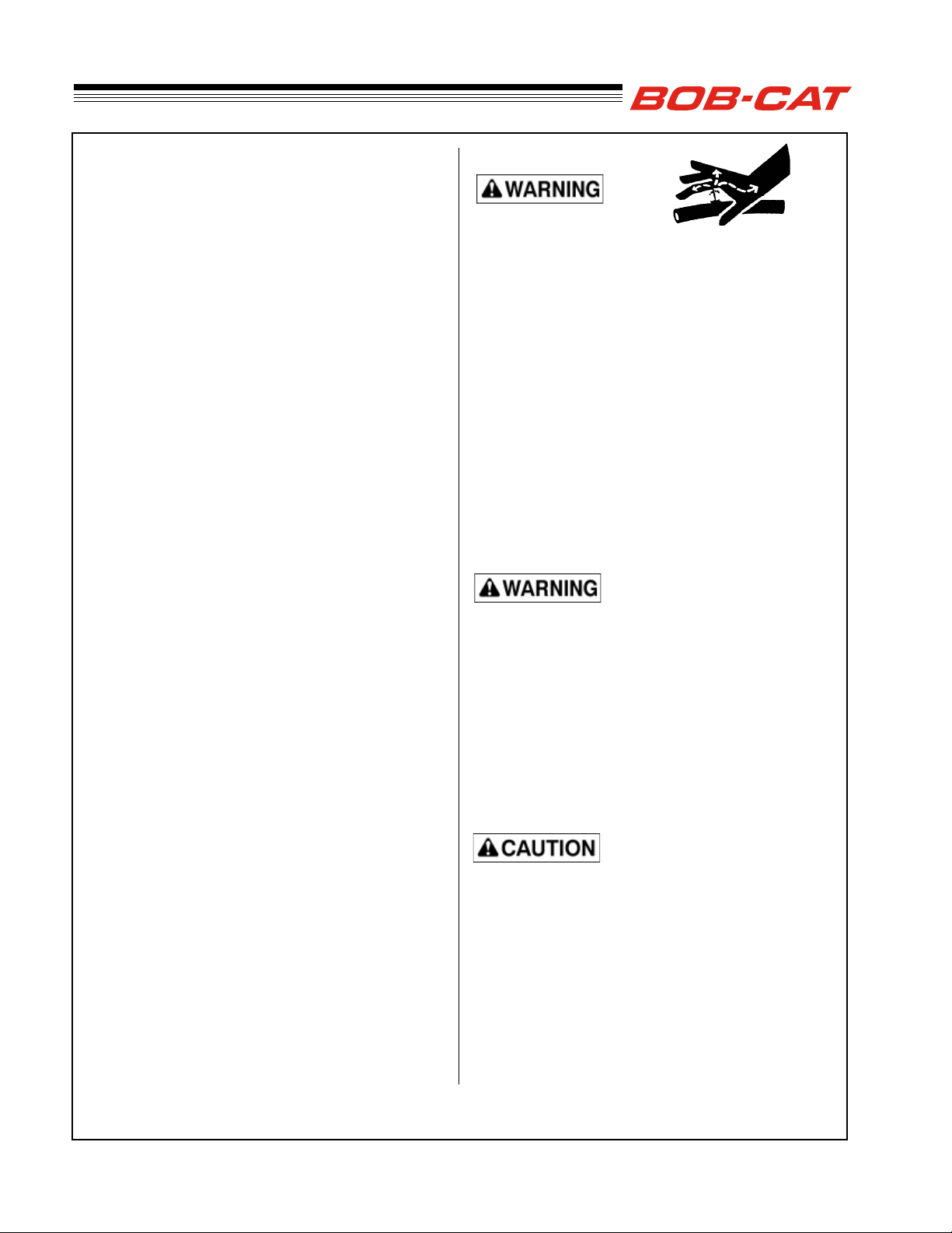
– Be aware that operating on wet grass, across
steep slopes or downhill may cause the mower to
lose traction. Loss of traction to the drive wheels
may result in sliding and loss of braking and
steering. Use a walk behind mower and /or hand
trimmer near drop-offs, ditches, steep banks or
water.
A ROPS is a Roll Over Protective Structure. The
ROPS reduces the risk of serious or fatal injury
in the unlikely event of a tip over, although the
system cannot protect the operator from all possible
injuries. It is not designed, made, or intended to
provide protection for a machine that is driven off an
embankment, retaining wall or similar situation. A
ROPS does not replace the need to exercise care
when operating on slopes.
IMPORTANT:
– The ROPS is an integral and effective safety
device. DO NOT remove or alter the ROPS.
– Keep Roll Bar in the raised position and use the
seat belt.
– There is NO roll over protection when the roll
bar is lowered. Lower the roll bar only when
necessary. DO NOT use the seat belt when the
roll bar is in the lowered position. Raise the roll
bar as soon as clearance permits.
– Do not cut, drill, modify or repair a ROPS
structure in any manner.
– Replace a damaged ROPS.
– Use extreme care when working close to fences,
ditches, trees, and on hills.
– Check overhead clearances carefully before
driving under any objects.
– DO NOT leave the operator's position while unit is
running.
– DO NOT carry passengers.

7
SAFETY
TRANSPORTING
Loading a machine onto a trailer or truck increases
the possibility of tip-over and could cause serious
injury or death.
– Use extreme caution when operating a machine on
a ramp.
– Have the ROPS in the up position and use the seat
belt when loading or unloading the machine unless
the ROPS will not clear the top of an enclosed
trailer.
– Use only a full-width ramp; do not use individual
ramps for each side of machine.
– Avoid sudden acceleration or deceleration while
driving the machine on a ramp as this could cause
a loss of control or a tip-over situation.
– Shut off fuel when transporting.
– Secure the machine to the truck or trailer.
WARNING
TOWING EQUIPMENT SAFETY
– Use extra caution when towing.
– Only tow equipment that has a hitch designed for
towing.
– Do not attach towed equipment except at the
hitch point.
– Follow manufacturer’s recommendations for
towed equipment, including weight limits and
towing on slopes. The weight of the towed
equipment may cause loss of traction or loss of
control. The mower will respond differently when
towing, particularly on slopes. Towed equipment
may cause loss of traction and loss of control.
For example, the load on a towed trailer may
shift during operation adversely affecting control
of the mower and towed equipment.
– Read all safety and operating instructions per-
taining to the mower and equipment before tow-
ing and understand and familiarize yourself with
the limitations of the mower and towed equip-
ment prior to towing.
– Always put the ROPS (Roll Over Protection
System) in the raised position before towing and
always use a seatbelt. Wear the seatbelt when-
ever the ROPS is raised.
– Always use extra caution when making tight
turns. Make wide turns to avoid jack- kning.
– Know the conditions such as wet grass/ground,
slopes, lose gravel, etc., as these factors will
affect the traction and handling characteristics of
the mower and towed equipment. For example,
wet grass reduces traction and control of the
mower and towed equipment.
– Travel slowly when towing and allow for extra
distance to stop.
– Never allow children or others in or on towed
equipment.
– Always park on level ground when towed equip-
ment is attached, and always apply the parking
brake when leaving the mower.
– Maximum weight of towed equipment recom-
mended for this mower is 700 lbs. when operat-
ing on at ground. Note: Maximum weight may
be reduced depending on specic conditions as
noted above. The operator must judge the condi-
tions and determine if towing is appropriate and
what maximum weight would be safe to tow.
– Maximum tongue weight should not exceed 25
lbs.
WARNING
NOTE: Never use transport speeds when towing or
when using a Grass Collection System.
WARNING

8
SAFETY
HYDRAULIC SYSTEM
Hydraulic uid escaping under pressure can pene-
trate skin and cause injury. Fluid accidentally inject-
ed into the skin must be surgically removed within a
few hours by a doctor familiar with this form of injury
or gangrene may result.
– If equipped, make sure all hydraulic uid hoses
and lines are in good condition and all hydraulic
connections and ttings are tight before applying
pressure to hydraulic system.
– Keep body and hands away from pinhole leaks or
nozzles that eject high pressure hydraulic uid.
– Use cardboard or paper, not your hands, to nd
hydraulic leaks.
– Safely relieve all pressure in the hydraulic system
by placing the motion control levers in neutral
and shutting off the engine before performing any
work on hydraulic system.
Charging or jump starting the battery may produce
explosive gases. Battery gases can explode causing
serious injury.
– Keep sparks, ames, or cigarettes away from
battery.
– Ventilate when charging or using battery in an
enclosed space.
– Make sure venting path of battery is always open
once battery is lled with acid.
– Always shield eyes and face from battery!
If the ignition is in the "ON" position there is potential
for sparks and engagement of components. Sparks
could cause an explosion or moving parts could ac-
cidentally engage causing personal injury. Be sure
ignition switch is in the "OFF" position before charg-
ing the battery.
MAINTENANCE SAFETY
In General
– Keep the machine in good working order.
– Maintain machine according to manufacturer's
schedule and instructions for maximum safety
and best mowing results.
– Park machine on level ground.
– Never allow untrained personnel to service ma-
chine.
– Adjust or repair only after the engine has been
stopped and the blades have quit rotating.
– Inspect grass catcher components regularly. If
worn, damaged or deteriorated, they may expose
moving parts or allow objects to be thrown.
– Replace worn, damaged or faulty parts. For best
results, always replace with parts recommended
by the manufacturer.
– Disconnect battery or remove spark plug wire(s)
before making any repairs. Disconnect the nega-
tive terminal rst and the positive last. Reconnect
positive rst and negative last.
– Do not dismantle the machine without releasing
or restraining forces which may cause parts to
move suddenly.
– Provide adequate support for lifted machine or
parts if working beneath.
– Keep hands or feet away from moving parts.
– Clean up oil or fuel spillage thoroughly.
– Replace faulty mufers.
– To reduce re hazards, keep the engine, mufer,
battery compartment and fuel storage area free
of grass, leaves, debris buildup or grease.
– Hydraulic uid can penetrate skin, use paper
to check for leaks. Relieve hydraulic pressure
before disconnecting hoses. Make sure
connections are tight and hoses are in good
condition.

9
SAFETY
BLADES
– Mower blades are sharp and can cut. Use extra
caution when handling. Remove obstructions
with care. Wrap the blade(s) or wear gloves.
– Be aware that rotating one blade on multi blade
mowers can cause other blades to rotate.
– Only replace blades. Never straighten or weld
them.
– Keep other persons away from blades.
BATTERY
Battery electrolyte contains sulfuric acid which is
poisonous and can cause severe burns. Swallowing
electrolyte can be fatal. Batteries can produce hydro-
gen gas which is explosive.
– When working with battery electrolyte, use
protective equipment such as, but not limited to,
goggles, face shield, rubber gloves and apron.
– Avoid leaning over a battery.
– Do not expose a battery to open ames or
sparks.
– Be sure batteries with ller caps are properly
lled with uid.
– Do not allow battery acid to contact eyes or skin.
Flush any contacted area with water immediately
and get medical help.
– Charge batteries in an open, well ventilated area,
away from sparks and ames. Unplug charger
before connecting or disconnecting from bat-
tery.
Jump starting
1. Be sure the jumper cables are in good condition.
Turn off the ignition and all electrical accessories
on both machines.
2. Position the machine with a good (charged) bat-
tery next to but not touching the machine with the
dead battery so jumper cables will reach.
3. When making cable connections:
- make sure the clamps do not touch anywhere
except to intended metal parts.
- Never connect a positive ("+" or red) terminal to
a negative ("–" or black) terminal.
- Make sure the cables won't get caught in any
parts after the engines are started.
4. Connect one end of the rst jumper cable to the
positive terminal on one battery. Connect the
other end to the positive terminal on the other
battery.
5. Connect one end of the other cable to the
negative terminal of the machine with a good
(charged) battery. Make the nal connection on
the engine of the machine to be started, away
from the battery.
6. Start the vehicle with the good battery, then the
machine with the discharged battery.
7. Remove the cables in the exact reverse order of
installation. When removing each clamp, take
care it does not touch any other metal parts while
the other end remains attached.
STORAGE SAFETY
– Stop the engine and allow to cool before storing.
– Drain the fuel tank outdoors only.
– Store fuel in an approved container in a cool, dry
place.
– Keep the machine and fuel containers in a
locked storage place to prevent tampering and to
keep children from playing with them.
– When the machine is to be parked, stored or left
unattended, lower the cutterdeck unless a posi-
tive mechanical lock is used.
– Do not store the machine or fuel container near
heating appliances with an open ame such as a
water heater or an appliance with a pilot light.
– Keep gasoline storage area free of grass, leaves
and excessive grease to reduce re hazard.
– Clean grass and debris from cutting units, drives,
mufers and engine to help prevent res.

10
LABELS
Leer el manual del operador. No permitir que personas no
•
capacitadas para ello usen la máquina.
Mantener los protectores en su lugar y sus tornillos
•
debidamente fijados.
Antes de limpiar, ajustar o reparar este equipo, apagar todos
•
los mandos, aplicar el freno de estacionamiento y apagar el
motor.
Mantener las manos, los pies y la ropa alejados de las piezas
•
en movimiento.
No conducir como pasajero ni llavar pasajeros en máquinas
•
sin asiento para ello.
Mantener a las demás personas alejadas durante el
•
funcionamiento de la máquina.
Si no sabe leer ingles, solicitarie a otra persona que le lea y
•
explique el contenido de las etiquetas y del manual de la
máquina.
AVOID SERIOUS INJURY OR DEATH:
Read and obey the Operation & Safety Manual.
•
Remove objects that could be thrown by the blades.
•
Use caution on slopes. Stay off slopes the machine cannot
•
back up.
Stop blades and drive down slowly if machine slides or stops
•
going on a slope.
Do not mow when children or others are around.
•
Do not carry a child or passenger - even with blades off.
•
Look down and behind before and while backing.
•
Do not operate unless trained.
•
Do not operate unless guards, shields, and interlocks are in
•
place and working.
Replace labels and Operation & Safety Manual if lost or
•
damaged.
BEFORE STARTING OR SERVICING:
Read and understand the
Operator's Manual & labels.
Be sure machine is in safe operating condition.
•
Move traction levers to neutral lock, parking brake to ON.
Set PTO switch to OFF.
•
BEFORE LEAVING SEAT:
•
Move traction levers to neutral lock, parking brake to ON.
•
Set PTO switch to OFF.
•
Turn engine keyswitch to OFF.
•
Remove key.
•
4175842
BELT ROUTING
Use 1/2” drive to
back tensioning idler
off to remove belt
from idler.
70 ft-lbs (95 n-m)
15 p.s.i.
(1.0 kg/cm²)
12 p.s.i.
(0.8 kg/cm²)
4175911
- Keep hands and
feet away.
- Stop engine and let
blades stop before
removing grass
collector or
unclogging.
- Keep area clear of
people and pets.
- Remove objects blade
may strike and throw.
- Do NOT operate without
chute, mulcher or entire
grass collector in place.
4164269
I
O
OFF
ON
P
PARKING
BRAKE
4167203
P
OPERATOR'S MANUAL
- Read and understand
- Replace if lost or
damaged
2000735

11
OPERATOR'S MANUAL IS LOCATED
UNDER THE FOOT PLATE.
4167202
4176399
LABELS
TO CHECK OR ADD
FUEL
-Do it outdoors.
-Stop engine. Allow to
cool.
-Do not smoke.
-Clean up spilled fuel.
-Do not overfill.
-Fill to one inch below
bottom of filler neck.
2000570
AVOID INJURY OR DEATH
FROM ROLL OVER:
Keep roll bar in the raised
position and use seat belt.
THERE IS NO ROLL OVER
PROTECTION WHEN THE
ROLL BAR IS LOWERED.
Lower the roll bar only
when necessary and
NEVER remove it.
Do NOT use seat belt when
the roll bar is down.
Raise the roll bar as soon
as clearance permits.
Read and follow all safety
instructions and warnings
in the operator’s manual.
ROLL OVER PROTECTION
STRUCTURE
To maintain opeartor
protection and roll bar
certification:
Replace a damaged roll
bar. DO NOT attempt to
repair or modify.
Any alteration of the roll
bar must be approved by
the manufacturer.
DO NOT exceed the
machine weight rating of
the roll bar.
WARNING
CAUTION
- Spring length for when installing
new belts only.
- Do NOT readjust after use.
4175231
10”±1/8”
- Spring length for when installing
new belts only.
- DO NOT readjust after use.
4176925
9.75”±1/8”
USED ON 61" MODELS
USED ON 52" MODELS
F
N
N
4165616 R
- Rotating parts.
- Do not operate with cover
removed.
WARNING
2000577
F
N
R4165615
N
- Spring length for when installing
new belts only.
- Do NOT readjust after use.
4177592
9.50”±1/8”
USED ON 48" MODELS 20A FUSE
20A FUSE
85 87
STARTER TRACTION
DELAY
CLUTCH
RELAY
RELAY
RELAY
RELAY
30C 86
85 87
30C 86
85 87
30C 86
85 87
30C 86
87A
4176226

12
LABELS
4175471
TRANSPORT
1
2
3
4
5
1
3
4
2
3
4
4
3
4
3
1
4
3
3
4
5
1
4
4
1
2
2
1
2
4
1
4
5
1
2
3
1
2
1
1
4
1
1
2
2
1
4
TRANSPORT
4175470
4
3
2
1
5
5
1
4
4
3
4
3
3
4
1
3
4
2
3
4
3
1
4
5
1
2
4
1
4
1
1
4
1
1
2
2
1
2
3
1
2
4
1
2
2
1
4
4176221
PINCH POINT
- Keep hands clear.
4176392
California Proposition 65
WARNING: Cancer and Reproductive Harm-
www.P65Warnings.ca.gov.
ADVERTENCIA: Cãncer and Daño Reproductivo-
www.P65Warnings.ca.gov.
Operation of this equipment may create sparks that can start
fires around dry vegetation. A spark arrestor may be required.
The operator should contact local fire agencies for laws or
regulations relating to fire prevention requirements.
SPARK ARRESTOR WARNING
4176807
WARNING
-Remove debris buildup. Debris under belt cover or near
muffler can cause fires.
-Blades continue to rotate for a few seconds after blades are
turned off.
-Blades must be at least 1/8” above bottom of housing.
-All blades must be identical. Check blade bolts daily for
tightness.
-Inspect for damage after stricking a foreign object.
Make repairs before restarting operation.
-Find and repair cause of any abnormal vibration. 2000572
4175482
SPARKS OR FLAME CAN START EXPLOSION.
DISCONNECT (-) NEGATIVE TERMINAL FIRST.
RECONNECT (-) NEGATIVE TERMINAL LAST.4175963
WARNING

13
C
L
M
T
P
K
FR
THROTTLE (T) - Move the throttle lever forward to
increase engine speed until the maximum governed
engine RPM is reached. Move the lever rearward to
decrease engine speed until the engine reaches its
idle speed.
CHOKE (C) - Pull the choke control out to set the
choke ON. Push it in to set the choke OFF.
KEYSWITCH (K) - The keyswitch has three
positions: OFF, RUN, and START. Insert the key
and turn it clockwise to move the switch from OFF to
RUN. Turn it further to START and hold to engage
the starter. Release the key and the switch will return
to RUN from START. Turn the key counterclockwise
to OFF to stop the engine.
FUEL GAUGE RH (FR) - Indicates fuel level in right-
side tank.
HOUR METER (M) - Records accumulated time the
machine is in operation.
POWER TAKE OFF (PTO) SWITCH (P) - The
operator must be in the seat when engaging the PTO
or the engine will kill. Pulling the PTO switch out
engages (turns on) the PTO and starts the blades
or other attachment. Pushing the PTO switch in
disengages (turns off) the PTO and stops the blades
or other attachment.
NOTE: The PTO switch does not control
attachments powered by a separate engine.
– Disengage the PTO whenever you stop or leave
the operator’s position.
– Shut off engine with the key and remove the
spark plug wires before making adjustments or
unplugging a clogged mower.
– Do not engage the PTO until ready to start
mowing.
LIGHT SWITCH (L) - Controls headlight on/off
(selected models)
CONTROLS
RIGHT SIDE CONTROL PANEL

14
DECK LIFT &
TRANSPORT LATCH LEVER (D & T) - Pull
back on the deck lift lever Dto raise the deck . When
the deck is completely raised, the transport latch T
engages to hold the deck in the transport position. To
lower the deck pull back on the lift lever D, then raise
the latch T. Lower the deck lift lever until it contacts
height of cut pin A.
HEIGHT OF CUT PIN (A) - Sets height of cut
and allows easy return from transport to desired
height of cut. Raise the deck to transport using the
foot pedal and deck lift lever D. Position pin Ain
the hole corresponding to the desired height of cut.
Lower the latch lever until it rests on pin A.
TRACTION LEVERS (L) - Each of the two trac-
tion levers controls the drive wheel located on the
same side. They control the forward and reverse
movement of the machine, provide steering and also
provide dynamic braking.
The operator must be in the seat and the parking
brake must be OFF or the engine will kill if the trac-
tion drive is engaged. To engage traction drive, move
the traction levers toward the center of the machine
until they are out of neutral lock position.
FUEL VALVE (U) - A fuel tank selector valve is
provided. The fuel tank selector valve has three posi-
tions:
Off: The tank selector is off when the lever points
down. The selector should be off whenever the
machine is transported or stands unused for any
length of time. Shutting off the fuel supply avoids the
possibility of ooding should any dirt get under the
carburetor oat needle. Leaving the tank selector in
either tank position can allow severe ooding, which
may ruin the engine by diluting the oil.
Right Tank: Fuel ows from the right tank when the
selector is turned 1/4 turn toward the right, when fac-
ing the valve.
Left Tank: Fuel ows from the left tank when the
selector is turned 1/4 turn toward the left, when fac-
ing the valve.
FUEL GAUGE LH (FL) - Indicates fuel level in
left-side tank.
12V OUTLET (O) - A 12V outlet is provided to
accommodate 12V accessories such as cell phone
chargers.
SWITCH BLANK (SW) - Shown with the dump
switch used with the optional grass collector or towed
aerator installed.
Located on left side control panel.
ARMREST REMOVED FOR CLARITY FL
SW
U
O
D
A
T
L
CONTROLS
Lift and Traction Levers
(operator's right side)

15
FOOT LIFT PEDAL (F)
The foot lift pedal F, allows the operator to raise the
mower deck to clear an object without removing his/
her hands from the traction controls. The foot pedal
may also be used to assist lifting the deck by hand.
Press on foot pedal Fto raise the deck.
PARKING BRAKE (R) - Pull the parking brake
lever up and back to put the parking brake ON. Push
it forward and down to put the parking brake OFF.
The parking brake must be ON to start the engine.
It must also be ON and the traction levers must be
in neutral to keep the engine running if the operator
leaves the seat. The parking brake must be OFF
to keep the engine running when a traction lever is
moved out of neutral lock.
TRACKING ADJUSTORS (W) - Adjusts track-
ing so machine can drive stright ahead with both
traction levers pushed fully forward.
CONTROLS
F
W
R

16
PUSHING THE MACHINE
PUSHING THE MACHINE
The machine may be pushed with the engine off, the
parking brake off, and the bypass valves open.
To open the bypass valves, move the parking brake
to the OFF position, then lift and pull bypass control
rod Cthrough the large opening D, until the control
rod stop is past the opening. Drop rod Cinto the
small opening to lock in place. Repeat for the other
bypass control rod.
To close the bypass valves, lift bypass control rod C
allowing the control rod stop to retract through the
large opening D.

17
PRE-OPERATION CHECK LIST
(OWNER’S RESPONSIBILITY)
___ Review and follow all safety rules and safety
decal instructions.
___ Check that all safety decals are installed and in
good condition. Replace if damaged.
___ Check to make sure all shields and guards
are properly installed and in good condition.
Be sure that either the discharge shield or
complete vacuum attachment is installed.
___ Check that all hardware is properly installed
and secured.
___ Check that equipment is properly and securely
attached to power unit.
___ Check to be sure engine is free of dirt and
debris. Pay particular attention to the cooling
ns, governor parts and mufer. Clean air
intake screen. Check air cleaner; service if
necessary.
___ Never allow riders.
___ Inspect area and remove stones, branches or
other hard objects that might be thrown,
causing injury or damage.
___ Clean area around oil ll dipstick. Remove
dipstick and check to be sure oil is in operating
range (between marks on dipstick). Add oil if
necessary but Do Not Overll. Install dipstick
assembly rmly until cap bottoms out on tube.
Dipstick assembly must always be secured into
ll tube when engine is running.
___ Check all lubrication points and grease as
instructed in manual.
___ Check hydrostatic uid level. Check to be sure
cooling ns on hydrostat are clean.
___ Perform a functional check of the safety
interlock system each time you operate the
unit.
PRE-OPERATION CHECKLIST

18
FUELING
– Fill fuel tanks with good quality, clean, unleaded
gasoline.
– Use a funnel to avoid spillage.
WARNING
TO CHECK OR ADD FUEL:
– Do it outdoors
– Do not smoke
– Stop engine; allow to cool
– Fill to one inch below bottom
of ller neck
– Do not overll
– Clean up spilled fuel
BEFORE STARTING THE ENGINE
– Be familiar with all controls, how each functions
and what each operates.
– Check the engine oil level and add if necessary.
– Check the fuel level and add if necessary. Using
the fuel selector valve, select which tank will sup-
ply fuel.
– Choke: For cold starts, set the throttle lever to
the half-open position and pull the choke out to
the ON position. For warm starts set the throttle
to the half-open position and the choke to the OFF
position.
OPERATOR PRESENCE
INTERLOCK SYSTEM
To start the engine:
–The PTO switch must be OFF.
–Both traction levers must be in the neutral lock
position.
–The parking brake must be ON.
To operate the machine:
1. The operator must be in the seat or engaging the
PTO will kill the engine.
2. The parking brake must be OFF and the opera-
tor must be in the seat, or moving a traction lever
from the neutral lock position will kill the engine.
STARTING THE ENGINE
1. Turn the key to operate the electric starter to start
the engine. Release the key when the engine
starts.
2. If the engine does not start immediately, do not
crank for more than 10 seconds at a time. Allow
60 seconds for the starter motor to cool down
between starting attempts to prevent the starter
motor from burning out.
3. If the choke is ON when the engine starts, gradu-
ally back it off until the engine runs with no choke
at all.
OPERATION
This manual suits for next models
3
Table of contents
Other Schiller Lawn Mower manuals

Schiller
Schiller BOBCAT XRZ FR651V KAW User manual

Schiller
Schiller BOB-CAT QUICKCAT 4000 Installation and operation manual

Schiller
Schiller BOB-CAT CRZ FR600V KAW W/48 SIDE DISCHARGE User manual

Schiller
Schiller BOB-CAT 942509J User manual

Schiller
Schiller BOB-CAT FASTCAT PRO SE-FX541V User manual

Schiller
Schiller BOB-CAT XRZ PRO FX651V KAW User manual

Schiller
Schiller BOB-CAT PROCAT FX730V KAW W/52 SIDE... User manual

Schiller
Schiller BOB-CAT PREDATOR PRO CV750 User manual

Schiller
Schiller BOB-CAT CRZ FR651V KAW W/48 SIDE DISCHARGE User manual

Schiller
Schiller BOB-CAT QUICKCAT 912480 User manual