manuals.online logo
Brands
  1. Home
  2. •
  3. Brands
  4. •
  5. Schlage
  6. •
  7. Accessories
  8. •
  9. Schlage B008Q5CTTG Manual

Schlage B008Q5CTTG Manual

A Directional signal strength
Wireless performance can vary depending on the orientation
of the advice. Depending on the device, max performance can
be directional or planar. In the example below, the wireless
signal is strongest from the front and back of the unit.
Refer to your device's instruction manual for details on
directional signal strength.
Strong
(back)
Weaker
Weaker
Strongest
(front)
Directional issues may be noticed with door sensors, for
example, when the sensor performs differently depending
on whether the door is open or closed. If communication is
inconsistent, please add an additional repeater.
Understanding Wireless Sensor
Setup and Signals
Wireless Signal Strength
B Signal Range
Wireless signals can reflect and bounce, but it is best to
assume that devices will communicate using a direct path.
However, signal range is impacted by sensor orientation,
obstacles between sensors, and the environment's RF noise.
C Repeater
When wireless devices can not be positioned so that the
direct signal path is within the areas of strong signal strength,
a repeater may be required to relay the signal.
The repeater should be positioned so that direct signal path
with each device is within the areas of strong signal.
REPEATERDEVICE DEVICE
Nexia devices, including the appliance module, dimmer module,
and wired thermostat, function as repeaters that can extend the
the range of wireless signals.
A Interference
For a successful wireless installation, it is critical to
understand that the wireless network is influenced by the
same environmental factors that affect other wireless systems.
Interference from radio emitters, various electronic devices,
and solid objects may degrade or stop communication.
Wireless competition
Too many wireless devices can saturate the
environment.
• Do not place Nexia Wireless devices, wireless routers,
or repeaters within 5 ft. of each other.
• Do not place radios of any type within 5 ft. of each
other. This includes not only these wireless controls
and sensors, but also wireless phones, security
systems, cameras, cell phones, stereo receivers, TV's,
baby monitors, cable boxes, HAM equipment, wireless
remotes, game systems, microwave ovens, etc.
Multipath Distortion
The RF signal will arrive at the receiver antenna by
many different paths all simultaneously.
• The arrival of the same signal by way of multiple paths
can lead to interference and a distorted signal. This
is often referred to as "multipath distortion" and leads
to "dead spots" around the home or room where the
range will be less than expected.
• Relocating a device can often address multipath
distortion issues.
> 5 FEET > 5 FEET
Control
or
Sensor
TV
Microwave
Avoiding Signal
Competition
Wireless Signal Interference
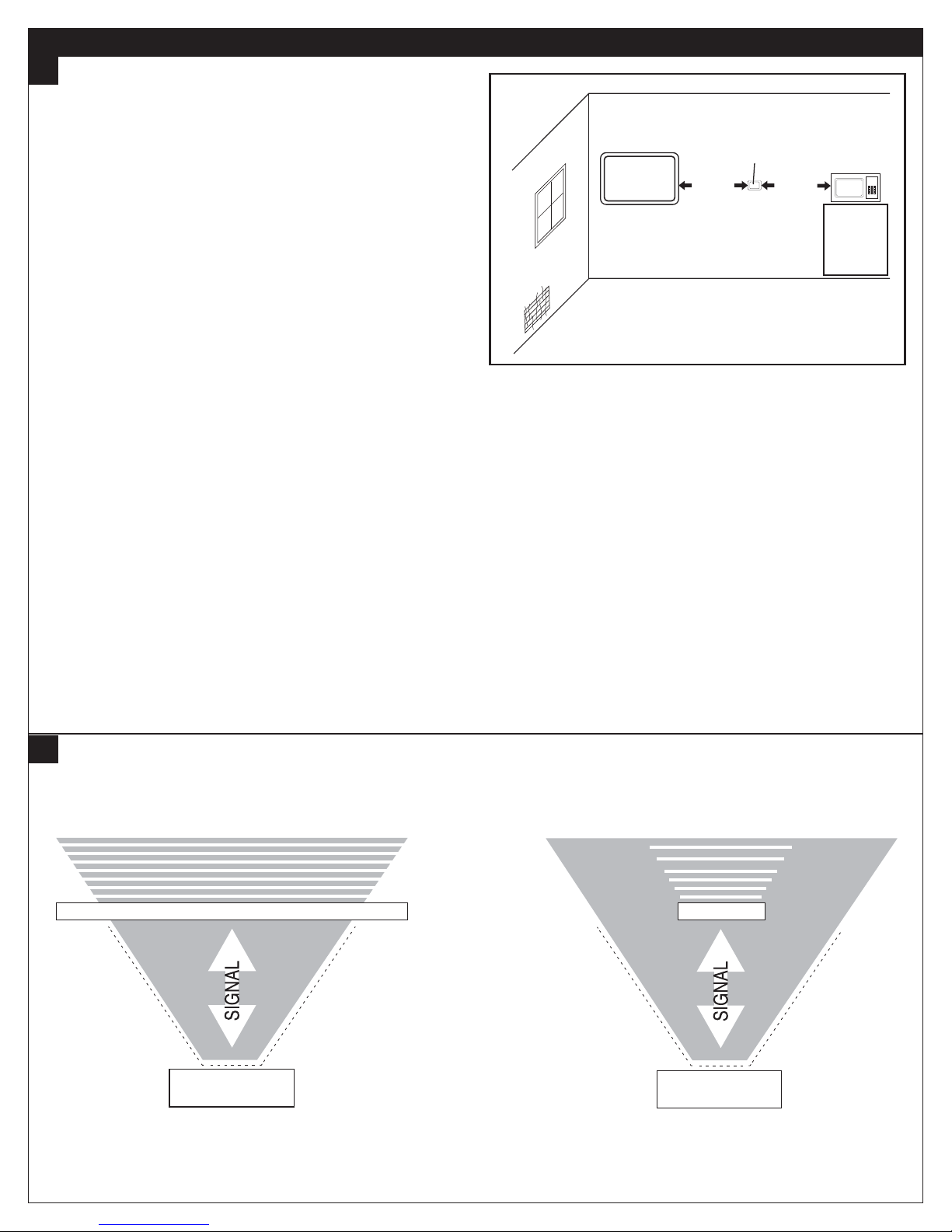
B Obstructions
Obstructions in the path of the signal degrade or reflect the signal.
Front
Device
Wall
Decreased
Signal
Front
Obstruction
Decreased
Signal
Device
C Materials That May Affect Signals
Metal objects, walls, and floors can affect wireless signals.
While not all-inclusive, a list of common construction and fabrication materials and their potential for adversely affecting
wireless signals is provided in the following table.
Impact of Materials on Signal Range
No Impact
to Signal
Wood
Plaster
Synthetic materials: plastic, Lucite, fabric, composites, glass (window or other clear glass)
Causes Moderate
Signal Loss
Water
Brick or cinder block
Marble or other soft stone
Causes Significant
Signal Loss
Ceramic Tile
Concrete
Granite or other hard stone
Bulletproof glass
Mirrors and smoked or tinted glass
Ferrous and nonferrous metal
D Signal Strength Through Objects
Signal strength is greater through less dense and nonmetallic objects.
Signal Strength
Stronger Weaker
s#UBICLEwALLSOFTCLOTHPArTITION^THIck)
sTYPICALFLOOR
sInterIORCONCRETEwALLTHIck)
sInterIORBricKwALLTHIck)
sInterIORDrywALLwALLGYPSUMWITHXSTUDS
s'LASSblocKwALLNONTINTED
sCerAMICTILEwALLTILEINSTALLEDovERGYPSUMWITHXSTUDS
s+ITCHENCOUNTERWITHgrANITECOUNTERTOPS
s'LASSWINDoWNOTTINTED
sDoubLEPANECOATEDGLASSTINTED
s3TEELFIREeXITDOOR
sInterIORwOODDOORHOLLow)
sInterIORwOODDOORSOLID
s(UMANBODY
E Mounting Considerations
Location
A wireless device may have significantly different signal
strengths if its position changes relative to other wireless
devices. If the sensor is losing communication with the
portal, you may be able to improve the signal strength by
moving it a short distance in any direction.
• Do not mount the sensor closer than 2 inches to any
pipes, duct work, or other metal obstructions.
• Avoid metal obstructions, concrete, or brick walls
between communicating devices.
Height
• For max coverage, devices are best placed at least
5 ft. above the floor, but not closer than 2 ft. from the
ceiling. Place wireless sensors as high as possible
in the location that offers the greatest amount of
unobstructed coverage within a room to guarantee
maximum connectivity.
• Unless an obstacle is in the way, all devices should be
at the same height for best performance.
• Placing a wireless device too close to the ground or
ceiling increases the likelihood of interference from
furnishing, support structures, rafters, or other objects.
5 FEET
Optimal
Zone
2 FEET
© 2012 Ingersoll Rand
24280026 Online Rev 10/12-a

Other Schlage Accessories manuals

Schlage P516-486 User manual

Schlage

Schlage P516-486 User manual

Schlage BE365 User manual

Schlage

Schlage BE365 User manual

Schlage NXRS100HC User manual

Schlage

Schlage NXRS100HC User manual

Schlage P516-485 User manual

Schlage

Schlage P516-485 User manual

Popular Accessories manuals by other brands

Datasensing SH4 STANDARD MUTING Product reference guide

Datasensing

Datasensing SH4 STANDARD MUTING Product reference guide

Baumer OBDM 12N6920/S35A manual

Baumer

Baumer OBDM 12N6920/S35A manual

Panasonic LA-511 instruction manual

Panasonic

Panasonic LA-511 instruction manual

Mammut PULSE Barryvox user manual

Mammut

Mammut PULSE Barryvox user manual

Vega VEGAFLEX 86 operating instructions

Vega

Vega VEGAFLEX 86 operating instructions

S+S Regeltechnik KYMASGARD AFTF-HK-FSE Operating Instructions, Mounting & Installation

S+S Regeltechnik

S+S Regeltechnik KYMASGARD AFTF-HK-FSE Operating Instructions, Mounting & Installation

Sensorplus 00999 manual

Sensorplus

Sensorplus 00999 manual

Intermatic AG4801 installation instructions

Intermatic

Intermatic AG4801 installation instructions

inventum HN138i instruction manual

inventum

inventum HN138i instruction manual

Aim M10 thread Documentation

Aim

Aim M10 thread Documentation

Appion G5Twin Operation manual

Appion

Appion G5Twin Operation manual

Orno OR-CR-255 quick start guide

Orno

Orno OR-CR-255 quick start guide

Geotech Seametrics Turbo instructions

Geotech

Geotech Seametrics Turbo instructions

Auriol HG03031A Operation and safety notes

Auriol

Auriol HG03031A Operation and safety notes

Omega ZW-CM user manual

Omega

Omega ZW-CM user manual

Vega VEGAFLEX 81 operating instructions

Vega

Vega VEGAFLEX 81 operating instructions

Baumer UNDK 20N6903/S35A manual

Baumer

Baumer UNDK 20N6903/S35A manual

Vega VEGAPULS 61 Quick setup guide

Vega

Vega VEGAPULS 61 Quick setup guide

manuals.online logo
manuals.online logoBrands
  • About & Mission
  • Contact us
  • Privacy Policy
  • Terms and Conditions

Copyright 2025 Manuals.Online. All Rights Reserved.