Aim M10 thread Operator's manual

Sensor documentation: Water thermoresistor – M10” thread – Version 1.01 1
SENSOR DOCUMENTATION 6/07/2004 TEMPERATURE
Notes: Water thermoresistor – M10 thread technical documentation, dimensions and pinout.
Version 1.01
Water
thermoresistor
M10 thread”
Figure 1: water thermoresistor – M10 thread – Rotax engines (side view)
Introduction
Aim instruments can measure and record the water temperature using a sensor (thermoresistor)
positioned in the pipe that goes from the radiator to the cylinder.
Installation notes
The water temperature sensor should be positioned inside the cylinder head: this sensor may be
used only with engines which accommodate the thermoresistor.
To install the water thermoresistor You just need to place it inside the screwed M10 hole located in
the cylinder head.
ATTENTION: While running the thermoresistor cable along the chassis, be careful to keep it as
far as possible from other cables (such as RPM or lap receiver cables) so to minimize interference
between them.
Aim suggests employment of our connection in sensor’s installation.
Inline water fitting (optional)
In the following drawing is represented the inline water fitting (optional), which is used to place
the water thermo resistor inside the pipe that goes from the radiator to the cylinder.
In order to firmly connect the fitting to the water pipe, Aim suggests You to use two wiring wraps.
SEZ A - A
A A
M10X1
15 [0.59]
19.5 [0.76]
11,8 [0.46]
18.5 [0.72]
46 [1.81]
37 [1.45]
Dimensions in millimetres [inches]
Figure 2: Inline water fitting
Sensor documentation: Water thermoresistor – M10” thread – Version 1.01 2
Software
Once the thermoresistor has been installed, it needs to be configurated. To correctly configure the
sensor, please use Race Studio 2, a software properly developed by Aim to configure your data
logger and analyze stored data.
In Race Studio 2 main window You can choose Your Aim
instrument. Once selected your gauge, please press “System
manager” button.
Please note: MyChron 3 Basic automatically recognizes the
sensor and needs no temperature sensor configuration.
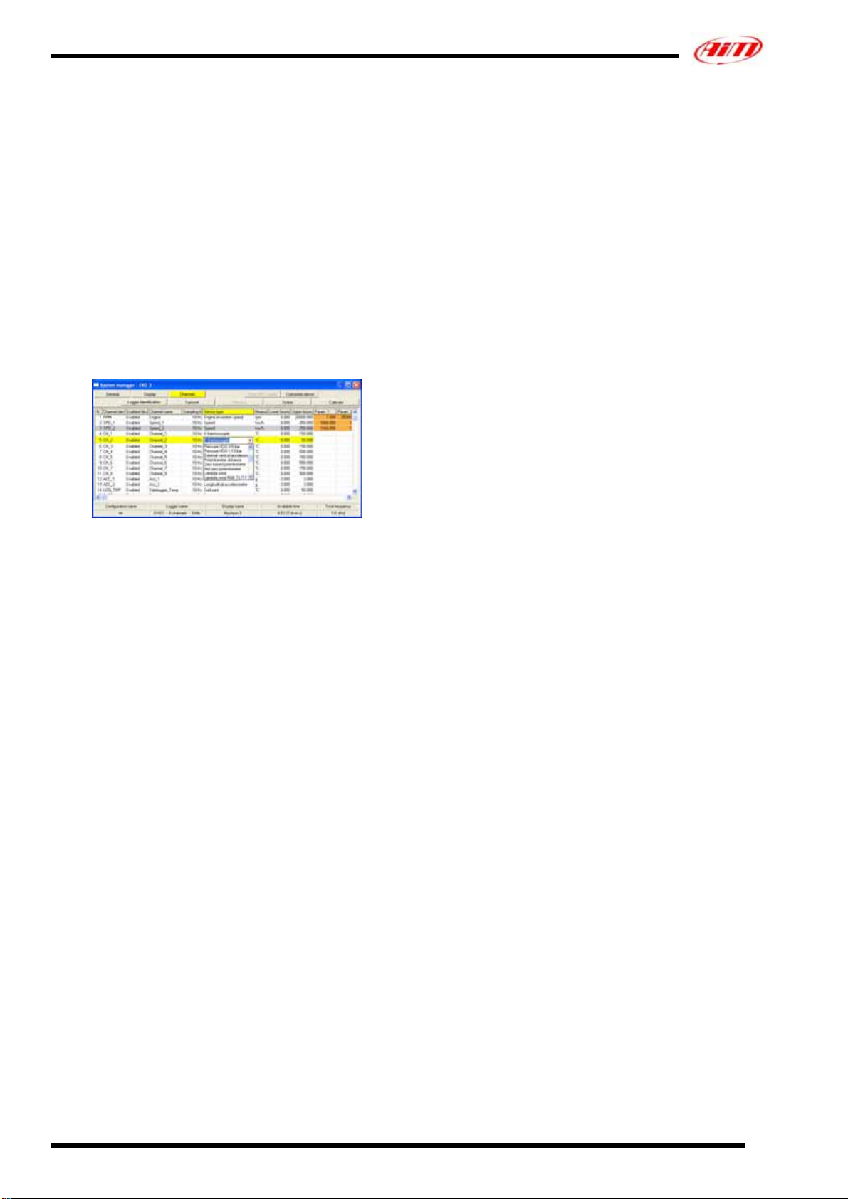
Sensor configuration
Once reached “System manager” main window, please press
“Channels” button to configure the sensor that you have
installed on your vehicle. The following screenshot appears.
To configure the sensor, please double-click in the box
corresponding to the “Sensor type” column and to the
“Ch_x” row (where x represents the channel number
where you wish to install the sensor): a menu like the one
reported in the previous screenshot appears.
Please, select “PT100 Thermoresistor” sensor.
Once selected the correct thermoresistor type, You need to
configure the visualization’s lower and upper boundary
values.
To set these values, please double-click in the row
corresponding to the channel where you have installed the
thermoresistor and in the columns corresponding to the
lower and upper boundary and fill the boxes with the
correct temperature value.
Please note: PT100 thermo resistors do not need
calibration.
Transmitting the configuration
Once the sensor has been correctly configured, please
transmit the configuration to your gauge pressing
“Transmit” button. During transmission, please DO
NOT SWITCH OFF the gauge.

Sensor documentation: Water thermoresistor – M10” thread – Version 1.01 3
Dimensions
Dimensions in millimeters [inches]
6.0 [0.24]
Pinout PT100 – MyChron 3 Kart
Pin Function Pin Function
1 + Temp. signal 3 Not connected
2 GND 4 Not connected
1
4
32
4 pins Binder 719 male connector: solder termination view
Pinout PT100 – MyChron 3 Car/Bike &
Dash ST1
Pin Function Pin Function
1 + Temp. signal 3 Not connected
2 GND 4 Not connected
32
41
2000 Ω 1%
4 pins Binder 719 male connector: solder termination view
Note: the PT100 thermoresistor for MyChron 3 Car/Bike/XG
and Dash ST1 is equipped with a 2 kΩ1% resistor between
pins number 1 and 4.
Technical characteristics
Description Value
Temperature range From 0° to 150°C [32°
to 302°F]
Cable length 250 mm [ 9.8” ]
Note 1: the water thermocouple is supplied with a 250 mm long
cable terminated with a 4 pins male Binder 719 connector.
Note 2: extension cables are available in standard lengths and,
on request, as specified dimensions.
15.1 [0.59]
M10X1
8.0 [0.32]
Other Aim Accessories manuals


