Vega VEGAFLEX 81 User manual

Operating Instructions
TDR sensor for continuous level and
interface measurement of liquids
VEGAFLEX 81
4 … 20 mA/HART - two-wire
Rod and cable probe
Document ID: 41824

2
Contents
VEGAFLEX 81 • 4 … 20 mA/HART - two-wire
41824-EN-170220
Contents
1 About this document
1.1 Function ........................................................................................................................... 4
1.2 Target group ..................................................................................................................... 4
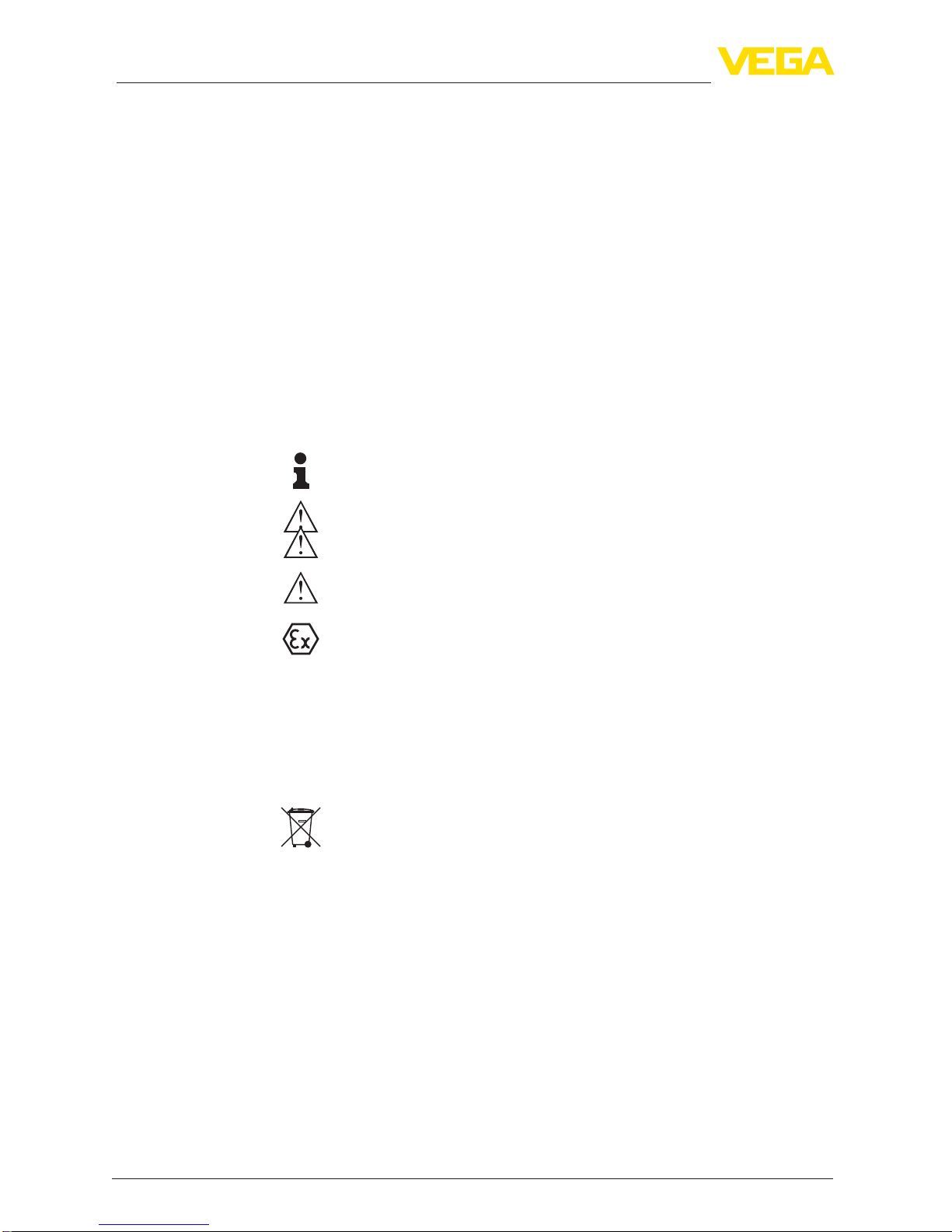
1.3 Symbols used................................................................................................................... 4
2 For your safety
2.1 Authorised personnel ....................................................................................................... 5
2.2 Appropriate use................................................................................................................ 5
2.3 Warning about incorrect use............................................................................................. 5
2.4 General safety instructions............................................................................................... 5
2.5 EU conformity................................................................................................................... 5
2.6 NAMUR recommendations .............................................................................................. 6
2.7 Installation and operation in the USA ............................................................................... 6
2.8 Environmental instructions ............................................................................................... 6
3 Product description
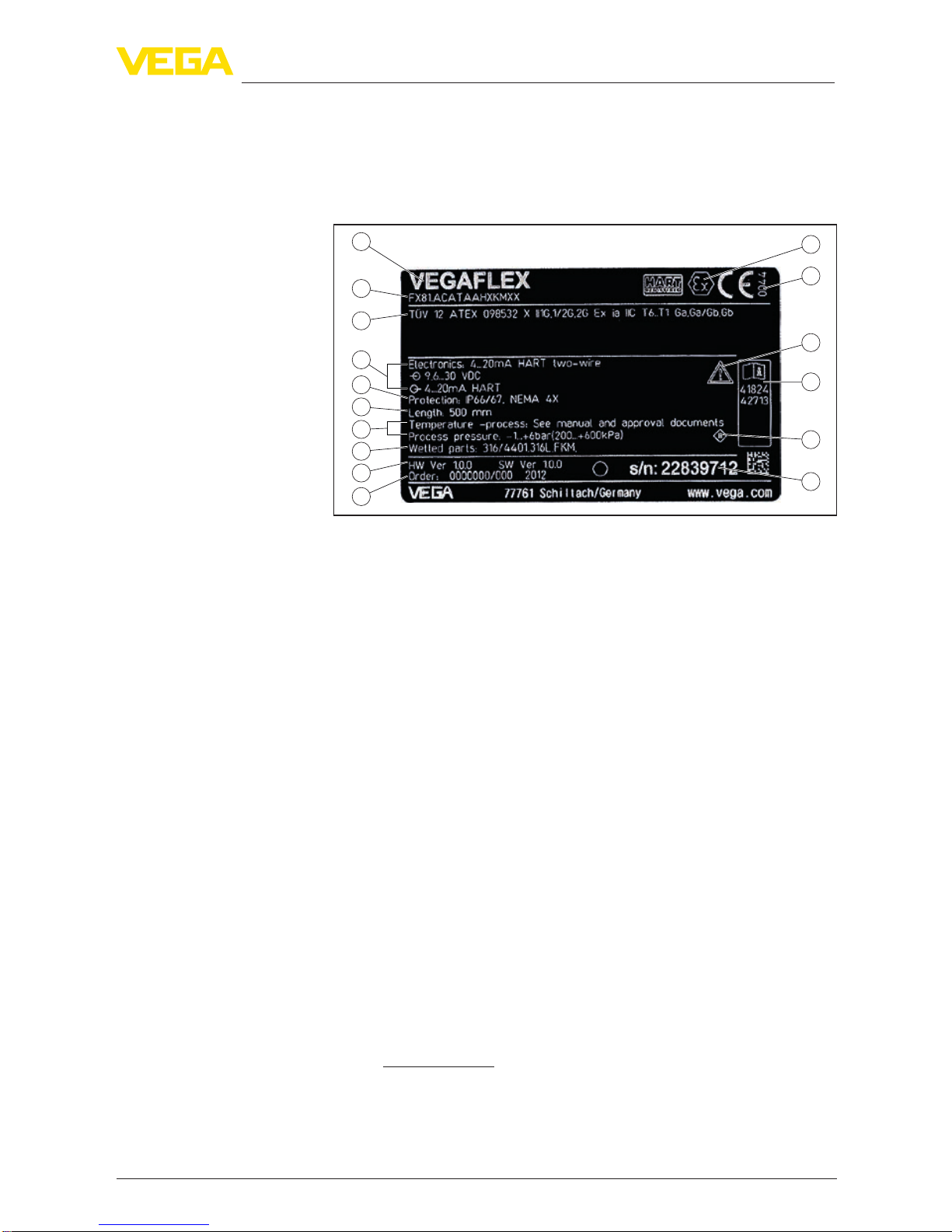
3.1 Conguration.................................................................................................................... 7
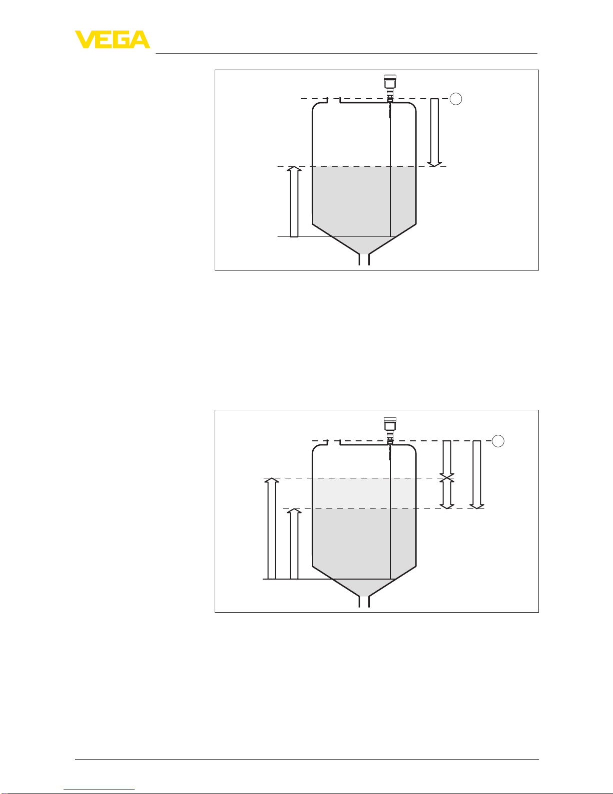
3.2 Principle of operation........................................................................................................ 8
3.3 Packaging, transport and storage................................................................................... 10
3.4 Accessories and replacement parts ............................................................................... 11
4 Mounting
4.1 General instructions ....................................................................................................... 14
4.2 Mounting instructions ..................................................................................................... 15
5 Connecting to power supply
5.1 Preparing the connection ............................................................................................... 24
5.2 Connecting..................................................................................................................... 25
5.3 Wiring plan, single chamber housing.............................................................................. 27
5.4 Wiring plan, double chamber housing ............................................................................ 27
5.5 Wiring plan, Ex-d-ia double chamber housing................................................................ 29
5.6 Double chamber housing with VEGADIS-Adapter.......................................................... 30
5.7 Wiring plan - version IP 66/IP 68, 1 bar........................................................................... 31
5.8 Supplementary electronics............................................................................................. 31
5.9 Switch-on phase............................................................................................................. 32
6 Set up with the display and adjustment module
6.1 Insert display and adjustment module............................................................................ 33
6.2 Adjustment system......................................................................................................... 34
6.3 Parameter adjustment - Quick setup .............................................................................. 36
6.4 Parameter adjustment - Extended adjustment................................................................ 36
6.5 Saving the parameterisation data................................................................................... 54
7 Setup with PACTware
7.1 Connect the PC.............................................................................................................. 55
7.2 Parameter adjustment with PACTware............................................................................ 56
7.3 Set up with the quick setup............................................................................................. 57
7.4 Saving the parameterisation data................................................................................... 58
8 Set up with other systems
8.1 DD adjustment programs ............................................................................................... 59
8.2 Field Communicator 375, 475 ........................................................................................ 59

3
Contents
VEGAFLEX 81 • 4 … 20 mA/HART - two-wire
41824-EN-170220
9 Diagnostics and servicing
9.1 Maintenance .................................................................................................................. 60
9.2 Diagnosis memory ......................................................................................................... 60
9.3 Status messages............................................................................................................ 61
9.4 Rectify faults................................................................................................................... 64
9.5 Exchanging the electronics module................................................................................ 67
9.6 Exchanging the cable/rod............................................................................................... 68
9.7 Software update ............................................................................................................. 70
9.8 How to proceed if a repair is necessary.......................................................................... 70
10 Dismount
10.1 Dismounting steps.......................................................................................................... 72
10.2 Disposal ......................................................................................................................... 72
11 Supplement
11.1 Technical data ................................................................................................................ 73
11.2 Dimensions .................................................................................................................... 86
11.3 Industrial property rights................................................................................................. 93
11.4 Trademark ...................................................................................................................... 93
Safety instructions for Ex areas
TakenoteoftheExspecicsafetyinstructionsforExapplications.
These instructions are attached as documents to each instrument
with Ex approval and are part of the operating instructions manual.
Editing status: 2017-02-02

4
1 About this document
VEGAFLEX 81 • 4 … 20 mA/HART - two-wire
41824-EN-170220
1 About this document
1.1 Function
This operating instructions manual provides all the information you
need for mounting, connection and setup as well as important instruc-
tionsformaintenanceandfaultrectication.Pleasereadthisinforma-
tion before putting the instrument into operation and keep this manual
accessible in the immediate vicinity of the device.
1.2 Target group
This operating instructions manual is directed to trained specialist
personnel.The contents of this manual should be made available to
these personnel and put into practice by them.
1.3 Symbols used
Information, tip, note
This symbol indicates helpful additional information.
Caution: If this warning is ignored, faults or malfunctions can result.
Warning: If this warning is ignored, injury to persons and/or serious
damage to the instrument can result.
Danger: If this warning is ignored, serious injury to persons and/or
destruction of the instrument can result.
Ex applications
This symbol indicates special instructions for Ex applications.
• List
The dot set in front indicates a list with no implied sequence.
→ Action
This arrow indicates a single action.
1 Sequence of actions
Numbers set in front indicate successive steps in a procedure.
Battery disposal
This symbol indicates special information about the disposal of bat-
teries and accumulators.

5
2 For your safety
VEGAFLEX 81 • 4 … 20 mA/HART - two-wire
41824-EN-170220
2 For your safety
2.1 Authorised personnel
All operations described in this operating instructions manual must
be carried out only by trained specialist personnel authorised by the
plant operator.
During work on and with the device the required personal protective
equipment must always be worn.
2.2 Appropriate use
VEGAFLEX 81 is a sensor for continuous level measurement.
Youcannddetailedinformationabouttheareaofapplicationin
chapter "Product description".
Operational reliability is ensured only if the instrument is properly
usedaccordingtothespecicationsintheoperatinginstructions
manual as well as possible supplementary instructions.
2.3 Warning about incorrect use
Inappropriate or incorrect use of the instrument can give rise to
application-specichazards,e.g.vesseloverllordamagetosystem
components through incorrect mounting or adjustment. Also the pro-
tectivecharacteristicsoftheinstrumentcanbeinuenced.
2.4 General safety instructions
This is a state-of-the-art instrument complying with all prevailing
regulations and guidelines. The instrument must only be operated in a
technicallyawlessandreliablecondition.Theoperatorisresponsible
for the trouble-free operation of the instrument.
During the entire duration of use, the user is obliged to determine the
compliance of the necessary occupational safety measures with the
current valid rules and regulations and also take note of new regula-
tions.
The safety instructions in this operating instructions manual, the na-
tional installation standards as well as the valid safety regulations and
accident prevention rules must be observed by the user.
For safety and warranty reasons, any invasive work on the device
beyond that described in the operating instructions manual may be
carried out only by personnel authorised by the manufacturer. Arbi-
traryconversionsormodicationsareexplicitlyforbidden.
The safety approval markings and safety tips on the device must also
be observed.
2.5 EU conformity
ThedevicefullsthelegalrequirementsoftheapplicableEUguide-
lines.ByaxingtheCEmarking,weconrmtheconformityofthe
instrument with these guidelines.

6
2 For your safety
VEGAFLEX 81 • 4 … 20 mA/HART - two-wire
41824-EN-170220
YoucanndtheEUconformitydeclarationonourwebsiteunder
www.vega.com/downloads.
Electromagnetic compatibility
Instruments in four-wire or Ex-d-ia version are designed for use in an
industrial environment. Nevertheless, electromagnetic interference
from electrical conductors and radiated emissions must be taken into
account, as is usual with class A instruments according to EN 61326-
1.Iftheinstrumentisusedinadierentenvironment,theelectromag-
netic compatibility to other instruments must be ensured by suitable
measures.
2.6 NAMUR recommendations
NAMUR is the automation technology user association in the process
industry in Germany. The published NAMUR recommendations are
acceptedasthestandardineldinstrumentation.
ThedevicefullstherequirementsofthefollowingNAMURrecom-
mendations:
• NE 21 – Electromagnetic compatibility of equipment
• NE 43 – Signal level for fault information from measuring transduc-
ers
• NE53–Compatibilityofelddevicesanddisplay/adjustment
components
• NE107-Self-monitoringanddiagnosisofelddevices
For further information see www.namur.de.
2.7 Installation and operation in the USA
This information is only valid for USA. Hence the following text is only
available in the English language.
Installations in the US shall comply with the relevant requirements of
the National Electrical Code (ANSI/NFPA 70).
Wiring methods must conform to all local and national codes govern-
ing the installation, and wiring must be rated for at least +10 °C above
the highest expected ambient temperature.
2.8 Environmental instructions
Protection of the environment is one of our most important duties.
That is why we have introduced an environment management system
with the goal of continuously improving company environmental pro-
tection.Theenvironmentmanagementsystemiscertiedaccording
to DIN EN ISO 14001.
Pleasehelpusfullthisobligationbyobservingtheenvironmental
instructions in this manual:
• Chapter "Packaging, transport and storage"
• Chapter "Disposal"

7
3 Product description
VEGAFLEX 81 • 4 … 20 mA/HART - two-wire
41824-EN-170220
3 Product description
3.1 Conguration
Thetypelabelcontainsthemostimportantdataforidenticationand
use of the instrument:
2
1
13
14
15
16
12
11
5
3
6
4
7
8
9
10
Fig. 1: Layout of the type label (example)
1 Instrument type
2 Product code
3 Approvals
4 Power supply and signal output, electronics
5 Protection rating
6 Probe length
7 Process and ambient temperature, process pressure
8 Material, wetted parts
9 Hardware and software version
10 Order number
11 Serial number of the instrument
12 Symbol of the device protection class
13 ID numbers, instrument documentation
14 Reminder to observe the instrument documentation
15 NotiedauthorityforCEmarking
16 Approval directives
The type label contains the serial number of the instrument. With it
youcanndthefollowinginstrumentdataonourhomepage:
• Product code (HTML)
• Delivery date (HTML)
• Order-specicinstrumentfeatures(HTML)
• Operating instructions and quick setup guide at the time of ship-
ment (PDF)
• Order-specicsensordataforanelectronicsexchange(XML)
• Testcerticate(PDF)-optional
Go to "www.vega.com", "VEGATools" and "Instrument search". Enter
the serial number.
Alternatively, you can access the data via your smartphone:
• Download the smartphone app "VEGATools" from the "Apple App
Store" or the "GooglePlayStore"
Type label
Serial number - Instru-
ment search

8
3 Product description
VEGAFLEX 81 • 4 … 20 mA/HART - two-wire
41824-EN-170220
• Scan the Data Matrix code on the type label of the instrument or
• Enter the serial number manually in the app
This operating instructions manual applies to the following instrument
versions:
• Hardware from 1.0.0
• Software from 1.3.0
• OnlyforinstrumentversionswithoutSILqualication
The instrument and the electronics version can be determined via the
product code on the type label as well as on the electronics.
• Standard electronics:Type FX80H.-
The scope of delivery encompasses:
• Sensor
• Optional accessory
• Optionally integrated Bluetooth module
• Documentation
– Quick setup guide VEGAFLEX 81
– Instructions for optional instrument features
– Ex-specic"Safety instructions" (with Ex versions)
– Ifnecessary,furthercerticates
• DVD "DTMCollection", included therein
– PACTware
– DTM Collection
– Instrumentmasterles(GSD)forProbusPA
– FDTcerticates
Information:
In this operating instructions manual, the optional instrument features
are described.The respective scope of delivery results from the order
specication.
3.2 Principle of operation
The VEGAFLEX 81 is a level sensor with cable or rod probe for
continuous level or interface measurement, suitable for applications
in liquids.
High frequency microwave pulses are guided along a steel cable or
a rod. Upon reaching the product surface, the microwave pulses are
reected.Therunningtimeisevaluatedbytheinstrumentandoutput-
ted as level.
Scope of this operating
instructions manual
Versions
Scope of delivery
Application area
Functional principle -
level measurement

9
3 Product description
VEGAFLEX 81 • 4 … 20 mA/HART - two-wire
41824-EN-170220
d
h
1
Fig. 2: Level measurement
1 Sensorreferenceplane(sealsurfaceoftheprocesstting)
d Distance to the level
h Height - Level
High frequency microwave impulses are guided along a steel cable or
rod. Upon reaching the product surface, a part of the microwave im-
pulsesisreected.Theotherpartpassesthroughtheupperproduct
andisreectedbytheinterface.Therunningtimestothetwoproduct
layers are processed by the instrument.
TS
d1
h1
h2
d2
1
L2
L1
L3
Fig. 3: Interface measurement
1 Sensorreferenceplane(sealsurfaceoftheprocesstting)
d1 Distance to the interface
d2 Distance to the level
TS Thicknessoftheuppermedium(d1-d2)
h1 Height - Interface
h2 Height - Level
L1 Lower medium
L2 Upper medium
L3 Gasphase
Functional principle - in-
terface measurement

10
3 Product description
VEGAFLEX 81 • 4 … 20 mA/HART - two-wire
41824-EN-170220
Upper medium (L2)
• The upper medium must not be conductive
• The dielectric constant of the upper medium or the actual distance
to the interface must be known (input required). Min. dielectric con-
stant:1.6.Youcanndalistofdielectricconstantsonourhome
page: www.vega.com.
• The composition of the upper medium must be stable, no varying
products or mixtures
• Theuppermediummustbehomogeneous,nostratications
within the medium
• Min. thickness of the upper medium 50 mm (1.97 in)
• Clear separation from the lower medium, emulsion phase or detri-
tus layer max. 50 mm (1.97 in)
• If possible, no foam on the surface
Lower medium (L1)
• The dielectric constant must be 10 higher than the dielectric
constant of the upper medium, preferably electrically conductive.
Example: upper medium dielectric constant 2, lower medium at
least dielectric constant 12.
Gas phase (L3)
• Air or gas mixture
• Gas phase - dependent on the application, gas phase does not
always exist (d2 = 0)
The instrument is always preset to the application "Level measure-
ment".
For the interface measurement, you can select the requested output
signal with the setup.
3.3 Packaging, transport and storage
Your instrument was protected by packaging during transport. Its
capacity to handle normal loads during transport is assured by a test
based on ISO 4180.
The packaging of standard instruments consists of environment-
friendly, recyclable cardboard. For special versions, PE foam or PE
foil is also used. Dispose of the packaging material via specialised
recycling companies.
Transport must be carried out in due consideration of the notes on the
transport packaging. Nonobservance of these instructions can cause
damage to the device.
The delivery must be checked for completeness and possible transit
damage immediately at receipt. Ascertained transit damage or con-
cealed defects must be appropriately dealt with.
Up to the time of installation, the packages must be left closed and
stored according to the orientation and storage markings on the
outside.
Prerequisites for inter-
face measurement
Output signal
Packaging
Transport
Transport inspection
Storage

11
3 Product description
VEGAFLEX 81 • 4 … 20 mA/HART - two-wire
41824-EN-170220
Unless otherwise indicated, the packages must be stored only under
the following conditions:
• Not in the open
• Dry and dust free
• Not exposed to corrosive media
• Protected against solar radiation
• Avoiding mechanical shock and vibration
• Storage and transport temperature see chapter "Supplement -
Technicaldata-Ambientconditions"
• Relative humidity 20 … 85 %
3.4 Accessories and replacement parts
The display and adjustment module PLICSCOM is used for measured
value indication, adjustment and diagnosis. It can be inserted into the
sensor and removed at any time.
The integrated Bluetooth module (optional) enables wireless adjust-
ment via standard adjustment devices:
• Smartphone/tablet (iOS or Android operating system)
• PC/notebook with Bluetooth USB adapter (Windows operating
system)
Youcanndfurtherinformationintheoperatinginstructions"Display
andadjustmentmodulePLICSCOM" (Document-ID 27835).
The interface adapter VEGACONNECT enables the connection of
communication-capable instruments to the USB interface of a PC. For
parameter adjustment of these instruments, the adjustment software
PACTware with VEGA-DTM is required.
Youcanndfurtherinformationintheoperatinginstructions"Interface
adapterVEGACONNECT" (Document-ID 32628).
The VEGADIS 81 is an external display and adjustment unit for VEGA
plics®sensors.
For sensors with double chamber housing the interface adapter
"VEGADISadapter" is also required for VEGADIS 81.
Youcanndfurtherinformationintheoperatinginstructions
"VEGADIS81" (Document-ID 43814).
The VEGADIS adapter is an accessory part for sensors with double
chamber housings. It enables the connection of VEGADIS 81 to the
sensor housing via an M12 x 1 plug.
Youcanndfurtherinformationinthesupplementaryinstructions
"VEGADISadapter" (Document-ID 45250).
VEGADIS 82 is suitable for measured value indication and adjustment
of sensors with HART protocol. It is looped into the 4 … 20 mA/HART
signal cable.
Youcanndfurtherinformationintheoperatinginstructions
"VEGADIS824…20mA/HART" (Document-ID 45300).
Storage and transport
temperature
PLICSCOM
VEGACONNECT
VEGADIS 81
VEGADIS adapter
VEGADIS 82

12
3 Product description
VEGAFLEX 81 • 4 … 20 mA/HART - two-wire
41824-EN-170220
PLICSMOBILE T61 is an external GSM/GPRS radio unit for transmis-
sion of measured values and for remote parameter adjustment of
plics®sensors. Adjustment is carried out via PACTware/DTM and the
integrated USB connection.
Youcanndfurtherinformationinthesupplementaryinstructions
"PLICSMOBILET61" (Document-ID 37700).
The protective cover protects the sensor housing against soiling and
intense heat from solar radiation.
Youwillndadditionalinformationinthesupplementaryinstructions
manual "Protective cover" (Document-ID 34296).
Screwedangesareavailableindierentversionsaccordingtothe
following standards: DIN 2501, EN 1092-1, BS 10, ASME B 16.5,
JIS B 2210-1984, GOST 12821-80.
Youcanndadditionalinformationinthesupplementaryinstructions
manual "FlangesaccordingtoDIN-EN-ASME-JIS".
The electronics module VEGAFLEX series 80 is a replacement part
forTDRsensorsofVEGAFLEXseries80.Thereisadierentversion
available for each type of signal output.
Youcanndfurtherinformationintheoperatinginstructionsmanual
"ElectronicsmoduleVEGAFLEXseries80".
The display and adjustment module can be optionally replaced by a
display and adjustment module with heating function.
You can use this display and adjustment module in an ambient tem-
perature range of -40 … +70 °C.
Youcanndfurtherinformationintheoperatinginstructions"Display
and adjustment module with heating" (Document-ID 31708).
If the standard sensor housing is too big or in case of strong vibra-
tions, an external housing can be used.
Then the sensor housing is made of stainless steel. The electronics is
located in the external housing which can be mounted in a distance of
up to 10 m (147 ft) to the sensor by using a connection cable.
Youcanndadditionalinformationintheoperatinginstructions
manual "Externalhousing" (Document-ID 46802).
If you are using an instrument in rod version, you can extend the rod
probewithcurvedsegmentsandrodextensionsofdierentlengths.
All extensions used must not exceed a total length of 6 m (19.7 ft).
The extensions are available in the following lengths:
Rod ø 12 mm (0.472 in)
• Basic segments: 20 … 5900 mm (0.79 … 232 in)
• Rod segments: 20 … 5900 mm (0.79 … 232 in)
• Curved segments: 100 x 100 mm (3.94 … 3.94 in)
PLICSMOBILE T61
Protective cover
Flanges
Electronics module
Display and adjustment
module with heating
External housing
Rod components

13
3 Product description
VEGAFLEX 81 • 4 … 20 mA/HART - two-wire
41824-EN-170220
Youcanndfurtherinformationintheoperatinginstructionsmanual
"RodandcablecomponentsVEGAFLEX80series".
The combination of a bypass tube and a VEGAFLEX 81 enables con-
tinuous level measurement outside the vessel.The bypass consists
of a standpipe which is mounted as a communicating container on
thesideofthevesselviatwoprocessttings.Thiskindofmounting
ensures that the level in the standpipe and the level in the vessel are
the same.
Thelengthandtheprocessttingscanbeconguredindividually.No
dierentconnectionversionsavailable.
Youcanndfurtherinformationintheoperatinginstructionsmanual
"BypasstubeVEGAPASS81".
If you mount the VEGAFLEX 81 in a bypass tube or standpipe, you
have to avoid contact to the bypass tube by using a spacer at the
probe end.
Youcanndadditionalinformationintheoperatinginstructions
manual "Centering".
If there is a risk of the cable probe touching the vessel wall during
operation due to product movements or agitators, etc., the measuring
probe can be strained.
Cables with a diameter up to 8 mm (0.315 in) can thus be strained.
For this purpose there is an internal thread (M12 or M8) in the gravity
weight.
Bypass tube
Centering
Fixing facility

14
4 Mounting
VEGAFLEX 81 • 4 … 20 mA/HART - two-wire
41824-EN-170220
4 Mounting
4.1 General instructions
Oninstrumentswiththreadedprocesstting,thehexagonmustbe
tightenedwithasuitablewrench.Fortheproperwrenchsizesee
chapter "Dimensions".
Warning:
The housing must not be used to screw the instrument in! Applying
tightening force can damage internal parts of the housing.
Protect your instrument against moisture ingress through the following
measures:
• Use the recommended cable (see chapter "Connectingtopower
supply")
• Tighten the cable gland
• Whenmountinghorizontally,turnthehousingsothatthecable
gland points downward
• Loop the connection cable downward in front of the cable gland
This applies mainly to outdoor installations, in areas where high
humidity is expected (e.g. through cleaning processes) and on cooled
or heated vessels.
Metric threads
In the case of instrument housings with metric thread, the cable
glands are screwed in at the factory. They are sealed with plastic
plugs as transport protection.
You have to remove these plugs before electrical connection.
NPT thread
In the case of instrument housings with self-sealing NPT threads, it is
not possible to have the cable entries screwed in at the factory. The
free openings for the cable glands are therefore covered with red dust
protection caps as transport protection.The dust protection caps do
notprovidesucientprotectionagainstmoisture.
Prior to setup you have to replace these protective caps with ap-
proved cable glands or close the openings with suitable blind plugs.
Make sure that all parts of the instrument exposed to the process are
suitable for the existing process conditions.
These are mainly:
• Active measuring component
• Processtting
• Process seal
Process conditions in particular are:
• Process pressure
• Process temperature
• Chemical properties of the medium
• Abrasionandmechanicalinuences
Screwing in
Protection against mois-
ture
Cable glands
Suitability for the process
conditions

15
4 Mounting
VEGAFLEX 81 • 4 … 20 mA/HART - two-wire
41824-EN-170220
Youcannddetailedinformationontheprocessconditionsinchapter
"Technicaldata" as well as on the type label.
4.2 Mounting instructions
Mount VEGAFLEX 81 in such a way that the distance to vessel instal-
lations or to the vessel wall is at least 300 mm (12 in). In non-metallic
vessels, the distance to the vessel wall should be at least 500 mm
(19.7 in).
During operation, the probe must not touch any installations or the
vessel wall. If necessary, fasten the probe end.
In vessels with conical bottom it can be advantageous to mount the
sensor in the center of the vessel, as measurement is then possible
nearly down to the lowest point of the bottom. Keep in mind that
measurement all the way down to the tip of the probe may not be pos-
sible.The exact value of the min. distance (lower dead band) is stated
in chapter "Technicaldata".
Fig. 4: Vessel with conical bottom
Plastic vessel/Glass vessel
The guided microwave principle requires a metallic surface on the
processtting.Therefore,inplasticvessels,etc.,useaninstru-
mentversionwithange(fromDN50)orplaceametalsheet
(ø>200mm/8in)beneaththeprocessttingwhenscrewingitin.
Makesurethattheplatehasdirectcontactwiththeprocesstting.
When mounting rod or cable probes in vessels without metal walls,
e.g.inplasticvessels,themeasuredvaluecanbeinuencedby
strongelectromagneticelds(emittedinterferenceaccordingto
EN 61326: class A). In this case, use a probe with coaxial version.
Installation position
Type of vessel

16
4 Mounting
VEGAFLEX 81 • 4 … 20 mA/HART - two-wire
41824-EN-170220
1 2
Fig. 5: Mounting in non-metallic vessel
1 Flange
2 Metal sheet
Ifpossible,avoidsockets.Mountthesensorushwiththevesseltop.
If this is not possible, use short sockets with small diameter.
Higher sockets or sockets with a bigger diameter can generally be
used.They can, however, increase the upper blocking distance (dead
band). Check if this is relevant for your measurement.
In such cases, always carry out a false signal suppression after
mounting.Youcanndfurtherinformationunder"Setup procedure".
h
d
dh
DN25...DN150
>DN150... DN200
≤ 150 mm (5.91")
≤ 100 mm (3.94")
Fig. 6: Mounting socket
Whenweldingthesocket,makesurethatthesocketisushwiththe
vessel top.
Mounting socket

17
4 Mounting
VEGAFLEX 81 • 4 … 20 mA/HART - two-wire
41824-EN-170220
1 2
Fig.7:Socketmustbeinstalledush
1 Unfavourable mounting
2 Socketush-optimummounting
Before beginning the welding work, remove the electronics module
from the sensor. By doing this, you avoid damage to the electronics
through inductive coupling.
Donotmounttheinstrumentsinorabovethellingstream.Makesure
thatyoudetecttheproductsurface,nottheinowingproduct.
Fig.8:Mountingofthesensorwithinowingmedium
The reference plane for the measuring range of the sensors is the
sealingsurfaceofthethreadorange.
Keep in mind that a min. distance must be maintained below the refer-
ence plane and possibly also at the end of the probe - measurement
in these areas is not possible (dead band).The length of the cable
can be used all the way to the end only when measuring conductive
products.Theseblockingdistancesfordierentmediumsarelisted
Welding work
Inowingmedium
Measuring range

18
4 Mounting
VEGAFLEX 81 • 4 … 20 mA/HART - two-wire
41824-EN-170220
in chapter "Technicaldata". Keep in mind for the adjustment that the
default setting for the measuring range refers to water.
Theprocessttingmustbesealedifthereisgaugeorlowpressurein
the vessel. Before use, check if the seal material is resistant against
the measured product and the process temperature.
Themax.permissiblepressureisspeciedinchapter"Technical
data" or on the type label of the sensor.
Standpipes or bypass tubes are normally metal tubes with a diameter
of 30 … 200 mm (1.18 … 7.87 in). Up to a diameter of 80 mm (3.15
in) such a tube corresponds to a coax measuring probe. Lateral inlets
inbypasstubesdonotinuencethemeasurement.
Measuring probes can be mounted in bypass tubes up to DN 200.
For bypass tubes, select the probe length such that the blocking
distance (dead band) of the probe is above and below the lower
lateralllingopeningsofthebypasstube.Youcanthusmeasurethe
complete range of the medium in the bypass tube (h). When design-
ing the bypass tube, keep the blocking distance of the probe in mind
andselectthelengthofthebypasstubeabovetheupperlaterallling
opening accordingly.
Microwaves can penetrate many plastics.This is why plastic tubes are
problematic for measurement applications. If durability is no problem,
we recommend the use of uncoated metal standpipes.
When the VEGAFLEX 81 is used in bypass tubes, contact with the
tube wall must be avoided. We recommend for this purpose a cable
probe with centering weight.
Caution:
When mounting, make sure that the cable is straight over its entire
length. A kink in the cable can cause measurement errors and contact
with the tube.
With rod probes, a spacer is generally not required. However, if there
is a risk of the rod probe being pressed against the tube wall by in-
owingmedium,youshouldmountaspacerattheprobeendtoavoid
contact with the tube wall. In the case of cable probes, the cable can
be strained.
Keep in mind that buildup can form on the spacers. Strong buildup
caninuencethemeasurement.
Pressure
Bypass tubes

19
4 Mounting
VEGAFLEX 81 • 4 … 20 mA/HART - two-wire
41824-EN-170220
1
2 3
h
Fig. 9: Mounting in a bypass tube - Position of the spacer or the centering weight
1 Rodprobewithspacer(PEEK)
2 Cableprobewithcenteringweight
3 Spacer(PEEK)onthegravityweightofacableprobe
h Measurable tube section
Note:
Measurement in a standpipe is not recommended for extremely adhe-
sive products. In case of slight buildup, you should choose a bypass
tube with bigger diameter.
Instructions for the measurement:
• The 100 % point in bypass tubes should be below the upper tube
connection to the vessel.
• The 0 % point in bypass tubes should be above the lower tube
connection to the vessel.
• A false signal suppression with installed sensor is generally rec-
ommended to achieve the best possible accuracy.
Standpipes or surge pipes are normally metal tubes with a diameter
of 30 … 200 mm (1.18 … 7.87 in). Up to a diameter of 80 mm (3.15
in), such a pipe corresponds to a coax measuring probe. It does not
matter if the standpipe is perforated or slotted for better mixing.
Measuring probes can be mounted in standpipes up to DN 200.
Standpipes

20
4 Mounting
VEGAFLEX 81 • 4 … 20 mA/HART - two-wire
41824-EN-170220
≥ 10 mm
(0.39")
≥ 10 mm
(0.39")
ø 150 - 200 mm
(5.91 - 7.87")
ø 150 - 200 mm
(5.91 - 7.87")
h
1
2
AB
3
Fig. 10: Mounting in a standpipe
1 Holes (for mixing)
2 Standpipe - vertically mounted - max. deviation 10 mm (0.4 in)
3 Ventilation opening
A Rod probe with spacer (steel)
B Cableprobewithcenteringweight
For standpipes, select the probe length such that the upper blocking
distance (dead band) of the probe is above the upper ventilation hole.
This allows you to measure the total level range of the medium in the
standpipe.When designing the standpipe, keep the upper blocking
distance of the probe in mind and plan the length above the upper
lateralllingopeningaccordingly.
Microwaves can penetrate many plastics.This is why plastic tubes are
problematic for measurement applications. If durability is no problem,
we recommend the use of uncoated metal standpipes.
When the VEGAFLEX 81 is used in standpipes, contact with the tube
wall must be avoided. We recommend for this purpose a cable probe
with centering weight.
Caution:
When mounting, make sure that the cable is straight over its entire
length. A kink in the cable can cause measurement errors and contact
with the tube.
Other manuals for VEGAFLEX 81
18
Table of contents
Other Vega Accessories manuals

Vega
Vega ATEX Installation instructions

Vega
Vega VEGAFLEX 82 User manual

Vega
Vega VEGAPULS 69 User manual

Vega
Vega VEGAFLEX 86 User manual

Vega
Vega VEGAPULS C 22 User manual

Vega
Vega VEGABAR 28 User manual

Vega
Vega VEGAPULS 62 User manual

Vega
Vega vegaflex 83 User manual

Vega
Vega VEGAPULS WL S 61 User manual

Vega
Vega VEGAPULS 62 User manual

Vega
Vega VEGAPULS 62 User manual

Vega
Vega VEGAFLEX 82 User manual

Vega
Vega VEGASON 61 User manual

Vega
Vega SOLITRAC 31 User manual

Vega
Vega VEGAPULS C 23 User manual

Vega
Vega VEGAPULS WL 61 User manual

Vega
Vega VEGAFLEX 81 User manual

Vega
Vega VEGASON 62 User manual

Vega
Vega PLICSMOBILE T81 User manual

Vega
Vega VEGAFLEX 65 User manual