Schlage ANT400 Series User manual

P516-099
ANT400
Optional remote antenna module instructions for
ANT400-REM-I/O, ANT400-REM-I/O+6dB, ANT400-REM-CEILING,
ANT400-REM-HALL
Para el idioma español, navegue hacia www.schlage.com/support.
Pour la portion française, veuillez consulter le site www.schlage.com/support.

2 • Schlage • ANT400 user guide
Contents
Overview...........................................................................................................................3
Getting started ..................................................................................................................3
Model specications .........................................................................................................4
Antenna location, safety and grounding ...........................................................................5
Location.........................................................................................................................5
Safety ...........................................................................................................................5
Grounding .....................................................................................................................5
Lightning protection.......................................................................................................5
Antenna radiation patterns................................................................................................6
Connect the coax cable ....................................................................................................8
Terminate the coax at the PIM400 or WRI400..................................................................9
Mounting the antenna ..................................................................................................... 11
Mounting the ANT400-REM-CEILING......................................................................... 11
Mounting the ANT400-REM-HALL.............................................................................. 11
Mounting the ANT400-REM-I/O or ANT400-REM-I/O+6dB ........................................12
Testing ............................................................................................................................13
Troubleshooting ..............................................................................................................14
FCC/IC statements .........................................................................................................15

3
Overview
The Schlage optional remote antenna module is an external antenna that provides a
means of increasing the radio frequency (RF) range between a Panel Interface Module
(PIM) and a Wireless Access Point Module (WAPM). WAPM’s include AD-400 locks,
Wireless Reader Interfaces (WRI400), Wireless Status Monitors (WSM400) and Wireless
Portable Readers (WPR400).
The remote antenna module is connected to the remote antenna connector on a PIM400 or
WRI400.
• Before installing a remote antenna module, read the user guide for the PIM400 or
WRI400 and the WAPM.
• As with all radio systems, interference may be a problem. Some causes of interference
are microwave ovens, certain lighting systems, microwave transmitters, or high speed
processors for computers.
Getting started
Follow these general steps when setting up a remote antenna module:
1. Install the PIM400 or the WRI400 in a designated location within 15 cable feet of where
the remote antenna will be located. (For more information on the PIM400 or WRI400,
see the installation guides that came with the products, or visit www.schlage.com/
support.)
2. Remove power from the PIM400 or WRI400.
3. Thoroughly check all national and local electrical codes regarding grounding and
lightning protection.
4. Familiarize yourself with the information contained in this user guide.
Save this user guide for future reference.

4 • Schlage • ANT400 user guide
Model specications
Remote antenna models
Model Location Description/Components
ANT400-REM-
CEILING Indoor
Omni-directional ceiling
mounted antenna, 15 foot
coax cable, and coax whip.
For indoor use with PIM400 or
WRI400.
ANT400-REM-HALL Indoor
Bi-directional ceiling or wall
mounted antenna, 15 foot
coax cable, and coax whip.
For indoor use with PIM400 or
WRI400.
ANT400-REM-I/O Indoor/
outdoor
Omni-directional at panel wall
or post mounted antenna, 15
foot coax cable, coax whip,
grounding kit (MGB+MCA5)
required for outdoor applications
(sold separately), and
articulated wall/post mounting
bracket.
ANT400-REM-
I/O+6dB
Indoor/
outdoor
Directional at panel wall or post
mounted antenna, 15 foot coax
cable, coax whip, grounding
kit (MGB+MCA5) required
for outdoor applications (sold
separately), and articulated wall/
post mounting bracket.
Accessories
Item Description/Components
MGB+MCA5 grounding kit
Grounding block (shown)
and 5 foot coax cable
(shown below), non-
plenum, N straight plug
both ends
15 foot cable non-plenum Coax cable, N straight plug
both ends
5 foot cable non-plenum kit
Note: A grounding block must be electrically connected to an earth ground that meets local code requirements.

5
Antenna location, safety and grounding
Location
All antenna models in this guide should be located according to the following requirements:
• Locate within 15 cable feet of the PIM400 or WRI400.
• Locate for best RF line-of-sight path with the WAPM that will be linked to the PIM400
or WRI400.
• Do not locate the antenna close to metal in frames, walls or oors.
Additional location and installation requirements for specic antenna models are provided in
the table below:
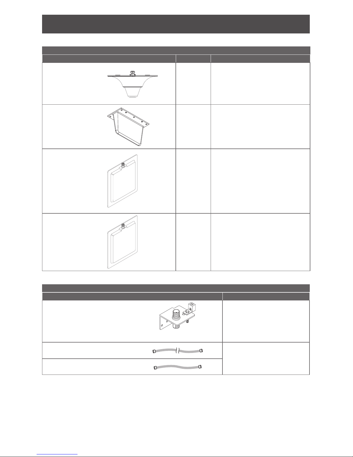
Antenna model Requirements
ANT400-REM-CEILING
ANT400-REM-HALL
• Intended for indoor applications.
• If local electrical code requires lightning protection, the
antenna must be installed with a grounding kit. See
Accessories on page 4 for more information.
• The ANT400-REM-HALL antenna’s vertical and horizontal
centerlines should be at right angles to the target antenna.
See ANT400-REM-HALL radio frequency radiation pattern
on page 7 for radio frequency beamwidth radiation
pattern specications.
ANT400-REM-I/O
ANT400-REM-I/O+6dB
• Intended for indoor or outdoor applications.
• Outdoor applications must be installed with a grounding kit.
• Local electrical code may require lightning protection
for indoor applications. If required, the antenna must be
installed with a grounding kit. See Accessories on page
4 for more information.
ANT400-REM-I/O+6dB
• The antenna’s vertical and horizontal centerlines should be
at right angles to the target antenna. See ANT400-REM-I/O
+6dB radio frequency radiaton pattern on page 6 for
radio frequency beamwidth radiation pattern specications.
Safety
WARNING - You can be seriously or fatally injured if this antenna comes in contact
with electric power lines or is brought in proximity with a high voltage electrical eld.
For your own safety, use extreme caution when installing this antenna. Keep away
from power lines!
Grounding
The National Electrical Code (NEC) requires that every antenna installation be properly
grounded. Local electrical codes may have additional requirements. Consult the NEC and
local electrical codes for information on proper grounding of the antenna system and other
antenna regulations.
A grounding kit compatible with all antenna models in this guide is available as an accessory.
See Accessories on page 4.
Lightning protection
All antenna models in this user guide are equipped with DC grounding. The only lightning
protection required is a grounding kit. See Accessories on page 4 for a grounding kit
available for use with all antenna models shown in this guide.

6 • Schlage • ANT400 user guide
Antenna radiation patterns
Vertical
Centerline
Horizontal Beamwidth
(75°)
Top View
Vertical Beamwidth
(65°)
Side View
Horizontal
Centerline
ANT400-REM-I/O+6dB radio frequency radiaton pattern

7
Side View
Top View
Horizontal Beamwidth
(Two beams each 60°)
Vertical
Centerline
Vertical Beamwidth
(60°)
Horizontal
Centerline
ANT400-REM-HALL radio frequency radiation pattern

8 • Schlage • ANT400 user guide
Connect the coax cable
The coax cable furnished with all antenna models:
• is suitable for outdoor installation
• should be routed with minimum bends, and when necessary any bend radius should be
greater than two (2) inches
• is properly terminated and should not be cut to length
• if there is excess coax, it should be coiled no less than eight (8) inches in diameter
• should not have excess coax placed inside or near the antenna, or inside the PIM400
enclosure.
LThe grounding block must be connected to earth ground.
LCable connections must be securely fastened.
LOutdoor antennas that are exposed to weather may require weatherproong on
coax connections.
Antenna
ANT400-REM-CEILING ANT400-REM-HALL
ANT400-REM-I/O
ANT400-REM-I/O+6dB
Application With lightning protection
Components
5 foot coax (non-plenum) N Type male both ends
Grounding kit N type female bulkhead both ends
15 foot coax (non-plenum) N type male straight
plug both ends
Coax whip N female bulkhead one end, reverse
MCX other end
OR OR
PIM400-485
(version 2)
PIM400-485 (version 1)
OR
PIM400-TD2 WRI400
Typical coax connections

9
Terminate the coax at the PIM400 or WRI400
1. Drill a B\,” (16 mm) hole in the enclosure at the proper location, depending on the
PIM400 model or WRI400 as shown below.
LTo avoid damage to electronics inside the enclosure, remove electronics from the
enclosure before drilling.
2. Install the N connector through the B\,” hole.
3. Connect the reverse MCX plug on the end of the coax whip to the PIM400 or WRI400
radio antenna board. The reverse MCX is a right angle connector.
4. Securely fasten the N connector through the B\,” hole using the lock washer and nut
provided.
Caution - Make sure the MCX plug stays secure.
PIM400-485 (version 2)
B\,” (16 mm)
1Z\v”
(32 mm)
1” (25 mm)
12-24 VDC
2I4
WIRE RDA–TDA–RDB+ TDB+GND AUXTAMPER
RX
I
TX
ATTENTION
ELECTROSTATIC
SENSITIVE DEVICE
POWER
TAMPER
PIM400-485
RS485
USB
MOUNT THIS SIDE UP
Nut
N Connector
Lock Washer
Reverse
MCX Plug
PIM400-485 (version 1) or PIM400-TD2
1Z\x" (38 mm)
Centered
B\,” (16 mm) Lock
Washer
Nut
Reverse
MCX Plug
N Connector

10 • Schlage • ANT400 user guide
WRI400
1Z\x" (38 mm)
Centered
B\,” (16 mm)
+-
+-
C
B+
1
+
+
1
1
GND
GND
IF RADIO BOARD PRESENT
NC
BATT
COIN CELL NOT NEEDED
NC
C
NO
C
NO
PRIMARY SIDE
BEEPER
BEEPER
ALARM
STRIKE
AUX
PWR/
SIDE UP
LINE
GND
RTE
GND
GND
111
1
RED
GRN
GND
DATA\D0
CLK\D1
GND
SWITCH INPUT
CLK\D1
DATA\D0
RED
GRN
READER1 READER2
TAMP2
TAMP1
DPS
RTX
GND
DEBUG
TAMPER
STATUS
RELAY
RX/TX
USB
+12V
+5V
LID
+3.3V
RX
TX
GND
OPEN
A-
1
11
1
1
1
1
1
23394075_C
SCHLAGE
LINK
RESET
TAMPER
GND
20
19
2
1
ICLK
IDAT
RB8
RB7
GND
VDD
MCLR
USB
AA
BATT
LINE
ALR_NC
ALR_C
ALR_NO
AUX
AUX
AUX
STR
STR
STR
RB+
TB+
TA-
RS485
12/24VDC
THIS
MOUNT
LED2
BATTERY_HOLDER1
R112
C61
U4
REL1
J3
J7
REL2
REL3
U5
TP25
TP24
TP23
TP22
TP21
J6
LED1
LED4
LED7
LED5
LED6
LED3
J18
J17
J13
LED8 LED9
C32
J9
J12
J11
J10
J8
S3
S2 S1
J5
J2
J1
Nut Lock Washer
N Connector
Reverse
MCX Plug
PIM400-485 (version 2) retrot:
2"
(51 mm)
B\,” (16 mm)
Centered
PIM400-485 (version 2) enclosure
12-24 VDC
2
I
4
WIRE RDA–TDA–RDB+ TDB+GND AUXTAMPER
RX
I
TX
ATTENTION
ELECTROSTATIC
SENSITIVE DEVICE
POWER
TAMPER
PIM400-485
RS485
+ POWER -
USB
MOUNT THIS SIDE UP
PIM400-485
(version 1)
enclosure
Reverse
MCX
plug
PIM400-485
(version 2)
Version 2 inside version 1 enclosure
1Z\x" (38 mm)
Centered
B\,” (16 mm)
PIM400-485 (version 1) enclosure

11
Mounting the antenna
Mounting the ANT400-REM-CEILING
1. Using the antenna enclosure as a template, mark the mounting holes.
2. Fasten the antenna enclosure to the ceiling using screws, and wall anchors if necessary
(not provided).
Mounting the ANT400-REM-HALL
1. Using the antenna enclosure as a template, mark the mounting holes.
2. Position the antenna so that the signal transmission is directed at the WAPM or
antenna target, as shown below.
3. Fasten the antenna enclosure to the wall or ceiling using screws, and wall anchors if
necessary (not provided).
Toward WAPM
(antenna target)
Toward WAPM
(antenna target)
ANT400-REM-HALL ceiling mount ANT400-REM-HALL wall mount

12 • Schlage • ANT400 user guide
Mounting the ANT400-REM-I/O or ANT400-REM-I/O+6dB
Follow the steps below to attach the antenna to the mounting kit, and secure the antenna to
the wall or a pole.
Tools required: Phillips
screwdriver
Adjustable
wrench
Drill with B\,”
(16 mm) bit
Torque
wrench
a. Place the antenna bracket
on the back of the antenna
as shown. Secure with
washers, helical spring lock
washers and 1/4-20 x B|,”
hex cap screws. Tighten
screws at a torque of 2.5
ft-lbf (3.4 N-m).
Lorem ipsum dolorsit amet, consectetuer
adipiscing elit, seddiam
nonummy nibh euismodtincidunt ut
0975837405273555
MADE I N ISRAEL
MARS
Lorem ipsum dolorsit amet
Lorem ipsum
Lorem ipsum
Lorem
ipsumdolor
sitamet
WATCH FOR
WIRES
YOU CA N BE
KILLED
DANGER
b. Connect the center portion
of the antenna bracket
as shown. Secure with a
washer, a helical spring
lock washer, 5/16-18 x 1Z\v”
hex cap screw and 5/16-18
hex nut. Leave screws
slightly loose.
Lorem ipsum dolorsit amet, consectetuer
adipiscing elit, seddiam
nonummy nibh euismodtincidunt ut
0975837405273555
MADE I N ISRAEL
MAR S
Lorem ipsum dolorsit amet
Lorem ipsum
Lorem ipsum
Lorem
ipsum dolor
sit amet
WATCH FOR
WIRES
YOU CA N BE
KILLED
DANGER
c. Connect the mounting
bracket portion of the
antenna bracket as shown.
Secure with a washer, a
helical spring lock washer,
5/16-18 x 1Z\v” hex cap
screw and 5/16-18 hex nut.
Leave screws slightly
loose.
Lorem ipsum dolorsit amet, consectetuer
adipiscing elit, seddiam
nonummy nibh euismodtincidunt ut
0975837405273555
MADE I N ISRAEL
MAR S
Lorem ipsum dolorsit amet
Lorem ipsum
Lorem ipsum
Lorem
ipsum dolor
sit amet
WATCH FOR
WIRES
YOU CA N BE
KILLED
DANGER

13
d. Wall Mount: Use the bracket as a template to mark the two mounting holes. Mount to
the wall using screws, and wall anchors if necessary (not provided). Fully tighten the
loose screws and nuts (steps b and c). Tighten all mounting bracket screws at a
torque of 30 inch lbs.
Pole Mount: Attach the
pole brackets to the pole
as shown. Secure the pole
brackets with two 5-inch
screws, a washer and a
helical spring lock washer
on each side. Adjust to
the desired angle. Fully
tighten the loose screws
(steps b and c). Tighten
all mounting bracket
screws at a torque of 2.5
ft-lbf (3.4 N-m).
Minimum diameter 1” (25 mm)
Maximum diameter 4C|v” (120 mm)
Pole mount shown
Testing
Test to verify that the antenna has been correctly installed:
LIf you encounter problems while performing the following tests, refer to the
Troubleshooting section in this guide and/or within the applicable WAPM user
guide.
1. Place the PIM400 into link mode. Refer to the PIM400-485 User Guide or the PIM400-
TD2 User Guide, in “Link Mode” section.
2. Place the WAPM into link mode. Refer to the AD400/AD401 or WRI400 User Guide, in
“Link to a PIM400” section.
3. Verify that the WAPM links successfully with the PIM400. Refer to the label located
inside the PIM400 enclosure for LED blink patterns that indicate successful linking.

14 • Schlage • ANT400 user guide
Troubleshooting
• Verify the PIM400 is in link mode. Status LEDs should be alternating green to red
continously.
• Verify the coax in the PIM400 or WRI400 is securely connected to the RF board. (See
reverse MCX plug connection on page 9.)
• Verify the N Type coax connectors are securely tightened on the PIM400 or WRI400, the
grounding kit (if installed), and at the antenna connection.
• Verify the antenna is properly mounted vertically.
• Locate the antenna for best RF line-of-sight path with the PIM400 or WRI400.
• Verify the antenna radiation pattern is properly aligned in the WAPM’s direction.
• Verify the WAPM is in link mode.
Find more troubleshooting information at www.schlage.com/support.

15
FCC/IC statements
The communication module is a 900 MHz transceiver for electronic locks and non-lock devices. The communication
module links the access device to the Access Control Management System, with feedback control to the Access
Device via a wireless means. The module contains the embedded rmware implementing the radio physical and
data layers. The antennas associated with this module are:
1. PCB trace inverted-L with a measured gain of 5.7dBi.
2. Omni, wall/post, indoors/outdoors.
3. Omni, ceiling, indoors.
4. Directional, wall/post, indoors/outdoors.
5. Bi-directional, ceiling, indoors.
Specications of the radio module:
Power Output: 19.6 dBm
Operating Frequency: 906 -924 MHz
Modulation: BPSK
NOTE: The intended use of this module is not for the general public. It is generally for industry/commercial use only.
This transceiver is to be professionally installed in the end product by Allegion, and not by a third party. The Schlage
AD-400 900 MHz communication board module will not be sold to third parties via retail, general public or mail order.
In the case of a repair, the transceiver will be replaced by a professional Installer.
Federal Communication Commission interference statement
This equipment has been tested and found to comply with the limits for a Class B digital device, pursuant to Part
15 of the FCC Rules. These limits are designed to provide reasonable protection against harmful interference in a
residential installation. This equipment generates uses and can radiate radio frequency energy and, if not installed
and used in accordance with the instructions, may cause harmful interference to radio communication. However,
there is no guarantee that interference will not occur in a particular installation. If this equipment does cause harmful
interference to radio or television reception, which can be determined by turning the equipment off and on, the user
is encouraged to try to correct the interference by one of the following measures:
• Reorient or relocate the receiving antenna.
• Increase the separation between the equipment and receiver.
• Connect the equipment into an outlet on a circuit different from that to which the receiver is connected.
• Consult the dealer or an experienced radio/TV technician for help.
This device complies with Part 15 of the FCC Rules. Operation is subject to the following two conditions: (1) This
device may not cause harmful interference, and (2) this device must accept any interference received, including
interference that may cause undesired operation.
FCC/IC caution
Any changes or modications not expressly approved by the party responsible for compliance could void the user’s
authority to operate this equipment. To comply with FCC/IC RF exposure limits for general population/uncontrolled
exposure, the antenna(s) used for this transmitter must be installed to provide a separation distance of at least
20 cm from all persons and must not be co-located or operating in conjunction with any other antenna or transmitter.
Industry Canada statements
Operation is subject to the following two conditions: (1) this device may not cause interference, and (2) this device
must accept any interference, including interference that may cause undesired operation of the device.
To reduce potential radio interference to other users, the antenna type and its gain should be so chosen that the
equivalent isotropically radiated power (e.i.r.p.) is not more than that permitted for successful communication.
This device has been designed to operate with the antennas listed below, and having a maximum gain of 9.3 dBi.
Antennas not included in this list are strictly prohibited for use with this device. The required antenna impedance is
50 ohms.
Approved antenna list
Model number
23530553 1 Remote antenna, Omni, wall/post, indoors/outdoors
23530561 1 Remote antenna, Omni, ceiling, indoors
23530579 1 Remote antenna, Directional, wall/post, indoors/outdoors
23530587 1 Remote antenna, Bi-directional, ceiling, indoors
To comply with IC RF exposure limits for general population/uncontrolled exposure, the antenna(s) used for this
transmitter must be installed to provide a separation distance of at least 20 cm from all persons and must not be
collocated or operating in conjunction with any other antenna or transmitter.

© Allegion 2014
P516-099 Rev. 03/14-d
P516-099
Customer Service
1-877-671-7011 www.allegion.com/us
This manual suits for next models
4
Table of contents
Popular Antenna manuals by other brands

Sirio Antenne
Sirio Antenne CX Series installation manual

International Antenna Company
International Antenna Company Double Bazooka INVERTED-L installation manual

Monster
Monster Just Hook It Up 140062-00 installation manual

Fermax
Fermax 5290 user manual

ANTARION
ANTARION AT0100 Installation and user manual

GSS
GSS STA 605 Assembly instructions

Intellian
Intellian i6W Installation and operation manual

HUSTLER
HUSTLER MX-2 installation instructions

Lectrosonics
Lectrosonics UMC16B instruction manual

Wilson Electronics
Wilson Electronics 301121 installation guide

DPM
DPM HN60 manual

Panorama Antennas
Panorama Antennas LP MM Series installation instructions