schmersal Praxi 100 User manual

Safe solutions for your industry
Manual MODBUS
Praxi 100

2
2
1. Safety _______________________________________________________________________ 4
1.1 Danger ___________________________________________________________________ 4
1.2 Warning __________________________________________________________________ 5
1.3 Earthing and earth fault protection ___________________________________________ 5
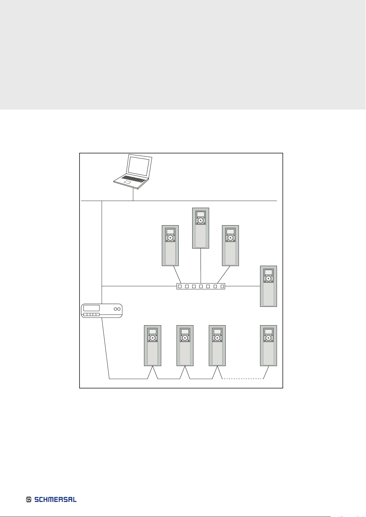
2. Modbus - General Info ________________________________________________________ 6
3. Modbus Technical Data _______________________________________________________ 8
3.1 Modbus RTU Protocol _____________________________________________________ 8
3.2 Modbus TCP Protocol _____________________________________________________ 8
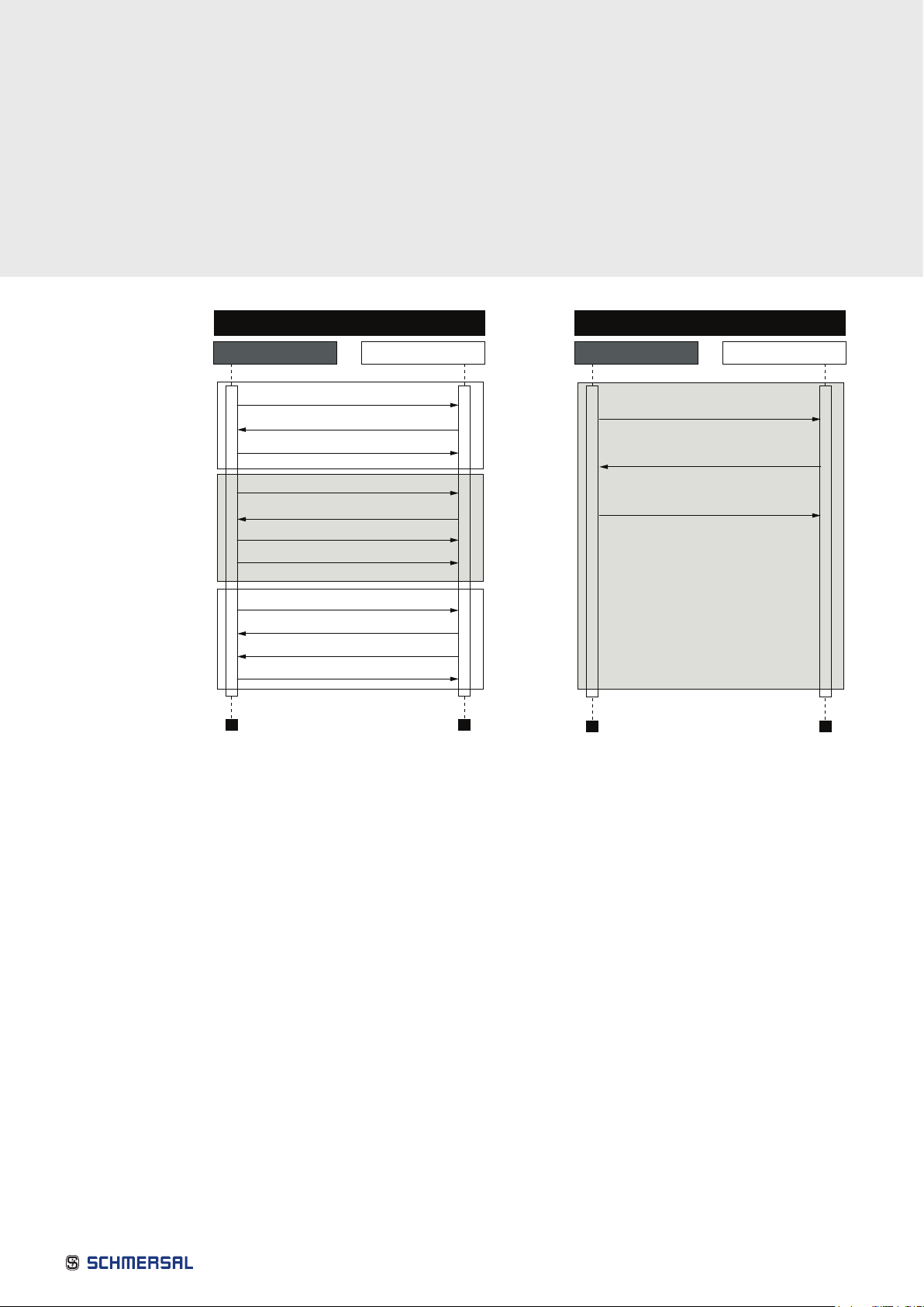
3.3 Modbus UDP vs TCP ______________________________________________________ 8
3.4 Connections and Wiring ____________________________________________________ 11
3.5 ACD (Address Conflict Detection) in Ethernet Network _________________________ 11
4. Installation ___________________________________________________________________ 12
4.1 Installation in Praxi®100 Family AC Drives ____________________________________ 12
4.1.1 Prepare for use Through Ethernet______________________________________ 13
4.1.2 Prepare for use Through RS485 _______________________________________ 15
4.2 Installation in Praxi®100 x __________________________________________________ 19
4.2.1 Prepare for use Through Ethernet______________________________________ 19
4.2.2 Prepare for use Through RS485 _______________________________________ 20
5. Fieldbus Parametrization _____________________________________________________ 22
5.1 Fieldbus Control and Basic Reference Selection_______________________________ 22
5.1.1 Torque Control Parametrization________________________________________ 22
5.1.2 Enabling Modbus Protocol____________________________________________ 23
5.2 Modbus RTU Parameters and Monitoring Values (M5.8.3) ______________________ 23
5.2.1 Slave Address_______________________________________________________ 24
5.2.2 Baud Rate __________________________________________________________ 24
5.2.3 Parity Type__________________________________________________________ 24
5.2.4 Stop Bits ___________________________________________________________ 24
5.2.5 Communication Timeout _____________________________________________ 24
5.2.6 Operate Mode_______________________________________________________ 24
5.2.7 IDMap IDs __________________________________________________________ 25
5.2.8 Fieldbus Protocol Status _____________________________________________ 25
5.2.9 Communication Status _______________________________________________ 25
5.2.10 Illegal Functions ____________________________________________________ 26
5.2.11 Illegal Data Address_________________________________________________ 26
5.2.12 Illegal Data Values __________________________________________________ 26
5.2.13 Slave Device Busy __________________________________________________ 26
5.2.14 Memory Parity Error ________________________________________________ 26
5.2.15 Slave Device Failure ________________________________________________ 26
5.2.16 Last Fault Response ________________________________________________ 26
5.2.17 Control Word_______________________________________________________ 26
5.2.18 Status Word _______________________________________________________ 26
5.3 Modbus TCP/UDP Parameters and Monitoring Values _________________________ 27
5.3.1 Ethernet Common Settings (M5.9.1) ___________________________________ 27
5.3.2 IP Address Mode ____________________________________________________ 27
5.3.3 Fixed IP Address ____________________________________________________ 27
5.3.4 Fixed Subnet Mask __________________________________________________ 28
5.3.5 Fixed Default Gateway _______________________________________________ 28
5.3.6 Active IP Address, Subnet Mask and Default Gateway ___________________ 28
Table of Contents

3
3
5.3.7 MAC Address _______________________________________________________ 28
5.3.8 Modbus TCP/UDP Settings (M5.9.2) ___________________________________ 28
5.3.9 Connection Limit ____________________________________________________ 29
5.3.10 Unit Identifier Number_______________________________________________ 29
5.3.11 Communication Timeout ____________________________________________ 29
5.3.12 IDMap IDs _________________________________________________________ 29
6. Communications _____________________________________________________________ 30
6.1 Data Addresses in Modbus Messages _______________________________________ 30
6.2 Supported Modbus Functions_______________________________________________ 30
6.3 Moldbus Data Mapping ____________________________________________________ 31
6.3.1 Coils Registers ______________________________________________________ 31
6.3.2 Clearing Resettable Counters _________________________________________ 31
6.3.3 Discrete inputs ______________________________________________________ 31
6.3.4 Holding registers and input registers ___________________________________ 32
6.3.5 Schmersal Application IDs ____________________________________________ 33
6.3.6 FB Process Data In __________________________________________________ 33
6.3.7 FB Process Data Out_________________________________________________ 34
6.3.8 ID Map _____________________________________________________________ 34
6.3.9 Operation Day Counter _______________________________________________ 36
6.3.10 Resettable Operation Day Counter____________________________________ 36
6.3.11 Energy Counter ____________________________________________________ 37
6.3.12 Resettable Energy Counter __________________________________________ 37
6.3.13 Fault History _______________________________________________________ 38
6.3.14 Fault History with 16-bit Error Codes__________________________________ 38
6.4 Modbus TCP/UDP Communication and Connection Timeout ___________________ 39
6.5 Example Messages ________________________________________________________ 40
6.5.1 Example 1 - Write Process Data _______________________________________ 40
6.5.2 Example 2 - Read Process Data _______________________________________ 41
6.5.3 Example 3 - Exception Response______________________________________ 42
7. Fault Tracing _________________________________________________________________ 43
7.1 Typical Fault Conditions ____________________________________________________ 43
7.2 RS - 485 Bus Biasing ______________________________________________________ 43
7.3 Other Fault Conditions _____________________________________________________ 44
8. Quick Setup__________________________________________________________________ 46
9. Appendix 1 - Process Data ____________________________________________________ 47
10. Appendix 2 - Control and Status Word ________________________________________ 48
10.1 Control Word Bit Description_______________________________________________ 48
10.2 Status Word Descriptions__________________________________________________ 50

4
1.1 Danger
1
The components of the power unit are live when the drive is connected to mains
potential. Coming into contact with this voltage is extremely dangerous and may
cause death or severe injury.
2The motor terminals U, V, W and the brake resistor terminals are live when the
AC drive is connected to mains, even if the motor is not running.
3
After disconnecting the AC drive from the mains, wait until the indicators on the
keypad go out (if no keypad is attached see the indicators on the cover). Wait 5
more minutes before doing any work on the connections of the drive. Do not
open the cover before this time has expired. After expiration of this time, use a
measuring equipment to absolutely ensure that no voltage is present. Always
ensure absence of voltage before starting any electrical work!
4
The control I/O-terminals are isolated from the mains potential. However, the
relay outputs and other I/O-terminals may have a dangerous control voltage
present even when the AC drive is disconnected from mains.
5Before connecting the AC drive to mains make sure that the front and cable
covers of the drive are closed.
6
During a ramp stop (see the Application Manual), the motor is still generating
voltage to the drive. Therefore, do not touch the components of the AC drive
before the motor has completely stopped. Wait until the indicators on the
keypad go out (if no keypad is attached see the indicators on the cover). Wait
additional 5 minutes before starting any work on the drive.
This manual contains clearly marked cautions and warnings which are intended for your personal
safety and to avoid any unintentional damage to the product or connected appliances.
Please read the information included in cautions and warnings carefully.
The cautions and warnings are marked as follows:
Table 1. Warning signs
= DANGER!
Dangerous voltagev
= WARNING or CAUTION
= Caution! Hot surface
1. Safety

5
1.2 Warning
1.3 Earthing and earth fault protection
1The AC drive is meant for xed installations only.
2Do not perform any measurements when the AC drive is connected to the mains.
3
The earth leakage current of the AC drives exceeds 3.5mA AC. According to
standard EN61800-5-1, a reinforced protective ground connection must be
ensured. See chapter 1.3.
4
If the AC drive is used as a part of a machine, the machine manufacturer is
responsible for providing the machine with a supply disconnecting device
(EN 60204-1).
5Only spare parts delivered by PRAXI®can be used.
6
At power-up, power break or fault reset the motor will start immediately if the
start signal is active, unless the pulse control for Start/Stop logic has been
selected. Futhermore, the I/O functionalities (including start inputs) may change
if parameters, applications or software are changed. Disconnect, therefore, the
motor if an unexpected start can cause danger.
7The motor starts automatically after automatic fault reset if the auto restart
function is activated. See the Application Manual for more detailed information.
8Prior to measurements on the motor or the motor cable, disconnect the motor
cable from the AC drive.
9Do not touch the components on the circuit boards. Static voltage discharge
may damage the components.
10 Check that the EMC level of the AC drive corresponds to the requirements of
your supply network.
The AC drive must always be earthed with an earthing conductor connected to the earthing terminal marked with .
The earth leakage current of the drive exceeds 3.5mA AC. According to EN61800-5-1, one or more of the following
conditions for the associated protective circuit shall be satised:
a. The protective conductor shall have a cross-sectional area of at least 10 mm2Cu or 16 mm2Al, through its total run.
b. Where the protective conductor has a cross-sectional area of less than 10 mm2Cu or 16 mm2Al, a second
protective conductor of at least the same cross-sectional area shall be provided up to a point where the protective
conductor has a cross-sectional area not less than 10 mm2Cu or 16 mm2Al.
c. Automatic disconnection of the supply in case of loss of continuity of the protective conductor.
The cross-sectional area of every protective earthing conductor which does not form part of the supply cable or cable
enclosure shall, in any case, be not less than:
■2.5mm2if mechanical protection is provided or
■4mm2if mechanical protection is not provided.
The earth fault protection inside the AC drive protects only the drive itself against earth faults in the
motor or the motor cable. It is not intended for personal safety.
Due to the high capacitive currents present in the AC drive, fault current protective switches may
not function properly.
Do not perform any voltage withstand tests on any part of the AC drive.
There is a certain procedure according to which the tests shall be
performed. Ignoring this procedure may result in damaged product.

6
2. Modbus - General Info
Modbus is a communication protocol developed by Modicon systems. In simple terms, it is a way of sending information
between electronic devices. The device requesting the information is called the Modbus Master (or the Client in Modbus
TCP/UDP) and the devices supplying information are Modbus Slaves (in Modbus TCP/UDP servers). The Master can
also write information to the Slaves. Modbus is typically used to transmit signals from instrumentation and control
devices back to a main controller or data gathering system.
Standard Modbus network contains one Master device and up to 247 Slave devices. In ModbusRTU and ModbusUDP
networks it is mandatory to dene a unique Slave Address (or Unit identier number) for the every Slave Device. Slave
Address is a number between 1 and 247. In ModbusTCP networks, it is not mandatory to dene a unique Slave Address,
because the IP address identies the device.
The Modbus communication interface is built around messages. The format of these Modbus messages is independent
of the type of physical interface used. The same protocol can be used regardless of the connection type. Because of
this, Modbus gives the possibility to easily upgrade the hardware structure of an industrial network, without the need
for large changes in the software. A device can also communicate with several Modbus nodes at once, even if they are
connected with different interface types, without the need to use a different protocol for every connection.
Figure 1. Basic structure of Modbus frame
11608_uk
Master´s
message
Slave
response
Start
Address
Function
Data
CRC
End
Start
Address
Function
Data
CRC
End
On simple interfaces like RS485, the Modbus messages are sent in plain form over the network. In this case the network
is dedicated to Modbus. When using more versatile network systems like TCP/IP over Ethernet, the Modbus messages
are embedded in packets with the format necessary for the physical interface. In that case Modbus and other types of
connections can co-exist at the same physical interface at the same time. Although the main Modbus message structure
is peerto- peer, Modbus is able to function on both point-to-point and multidrop networks.
Each Modbus message has the same structure. Four basic elements are present in each message. The sequence of these
elements is the same for all messages, to make it easy to parse the content of the Modbus message. A conversation
is always started by a master in the Modbus network. A Modbus master sends a message and—depending of the
contents of the message—a slave takes action and responds to it. There can be more masters in a Modbus network.
Addressing in the message header is used to dene which device should respond to a message. All other nodes on the
Modbus network ignore the message if the address eld does not match their own address.

7
Figure 2. Principal example diagram of Modbus
Your Praxi 100 family AC drive is equipped with Modbus support as standard. If you need to contact Praxi service in
problems related to Modbus, send a description of the problem together with the Drive Info File taken with Praxi Live to
customer support. If possible, also send a “Wireshark” log from the situation if applicable.
Ethernet
Modbus TCP
Modbus RTU
Modbus
RTU
master
Switch
11781_uk

8
3. Modbus Technical Data
3.1 Modbus RTU Protocol
3.2 Modbus TCP Protocol
3.3 Modbus UDP vs TCP
Connections and
communications
Interface RS-485
Data transfer method RS-485 MS/TP, half-duplex
Transfer cable STP (Shielded Twisted Pair), type Belden 9841 or similar
Connector 2.5 mm2
Electrical isolation Functional
Modbus RTU As described in “Modicon Modbus Protocol Reference Guide”
Bitrate 300, 600, 1200, 2400, 4800, 9600, 19200, 38400, 57600, 76800, 115200
and 230400 bits/s
Addresses 1 to 247
Connections and
communications
Interface 100BaseTX, IEEE 802.3 compatible
Data transfer method Ethernet half/full -duplex
Data transfer speed 10/100 MBit/s, autosensing
Protocol Modbus TCP
Connector Shielded RJ45 connector
Cable type CAT5e STP
Modbus TCP As described in Modbus Messaging Implementation Guide
Default IP Selectable: Fixed or DHCP (AutoIP)
Table 2.
Table 3.
In addition to TCP, the Praxi 100 family AC drive supports also UDP starting from following rmware versions:
■Praxi 100 INDUSTRIAL and Praxi 100 X: FW0072V025
■Praxi 100 FLOW: FW0159V016
■Praxi 100 HVAC: FW0065V035
It is recommended that UDP is used when reading and writing rapidly and repetitively (cyclically) the same data as in case
of process data. TCP must be used for single operations, like service data (e.g. reading or writing parameter values).
The key difference between UDP and TCP is that when using TCP, each and every Modbus frame needs to be acknowledged
by the receiver (see the gure below). This adds extra trafc to the network and more load to the system (PLC and drives)
because software needs to keep track of sent frames to make sure that they have reached their destination.

9
Connections and
communications
Interface RS-485
Data transfer method RS-485 MS/TP, half-duplex
Transfer cable STP (Shielded Twisted Pair), type Belden 9841 or similar
Connector 2.5 mm2
Electrical isolation Functional
Modbus RTU As described in “Modicon Modbus Protocol Reference Guide”
Bitrate 300, 600, 1200, 2400, 4800, 9600, 19200, 38400, 57600, 76800, 115200
and 230400 bits/s
Addresses 1 to 247
Connections and
communications
Interface 100BaseTX, IEEE 802.3 compatible
Data transfer method Ethernet half/full -duplex
Data transfer speed 10/100 MBit/s, autosensing
Protocol Modbus TCP
Connector Shielded RJ45 connector
Cable type CAT5e STP
Modbus TCP As described in Modbus Messaging Implementation Guide
Default IP Selectable: Fixed or DHCP (AutoIP) Another difference between TCP and UDP is that UDP is connectionless. TCP connections are always opened with TCP
SYN messages and closed with TCP FIN or TCP RST. With UDP, the rst packet is already a Modbus query. IP address
and port combination is treated as a connection. If port number changes, it is considered as a new connection or as a
second connection if both stay active.
When using UDP, it is not guaranteed that the sent frame reaches its destination. The PLC must keep track of the
Modbus requests by using the Modbus transaction id-eld. It actually must do this also when using TCP. If the PLC does
not receive response in time from the AC drive in UDP connection, it needs to send the query again. When using TCP,
the TCP/IP stack will keep resending the request until it has been acknowledged by the receiver (see Figure 4). If the PLC
sends new queries during this time, some of those may not be sent to the network (by TCP/IP stack) until previous sent
package(s) has been acknowledged. This can cause small packet storms when the connection is resumed between the
PLC and the AC drive (see Figure 5).
11716_uk
Modbus TCP Communication
PLC
Open
Connection
Communicate
Communicate
Close
Connection
Drive
TCP, SYN
TCP, SYN, ACK
TCP, ACK
Modbus Query
Modbus Query
Modbus Response, TCP, ACK
TCP, ACK
TCP, ACK
TCP, ACK
TCP, ACK
TCP, FIN, ACK
Modbus UDP Communication
PLC Drive
Modbus Query
Modbus Response
Modbus Query
Figure 3. Modbus TCP and UDP communication comparison

10
11717_uk
Modbus TCP Communication
PLC Drive
Modbus Query (1)
Modbus Query (2)
Modbus Response (1), TCP, ACK
Modbus Response (2), TCP, ACK
TCP, ACK
TCP retransmission, Modbus Query (2)
Normal communication continues
Packet lost, no response
Modbus Query (1)
Modbus Response (1)
Modbus Response (4)
Modbus Query (2)
Modbus Query (3)
Modbus Query (4)
Packet lost, no response
Normal communication continues
Modbus UDP Communication
PLC Drive
11718_uk
Modbus TCP Communication
PLC Drive
Modbus Modbus
TCP
stack
TCP
stack
Modbus Query (1)
Modbus Query (2)
Modbus Query (3)
Modbus Query (4) Modbus Query
(1, 2, 3)
Modbus Query (4)
Modbus Response
(1, 2, 3)
Modbus Response
(4)
TCP Modbus Query
TCP, ACK
TCP, ACK
TCP, ACK
TCP, ACK
TCP, Modbus Response (1, 2, 3)
TCP, Modbus Response (4)
TCP, Modbus Query (4)
Retransmission
Modbus Query (1, 2, 3)
Retransmission Modbus Query (1, 2, 3)
Retransmission
Modbus Query (1, 2)
Retransmission
Modbus Query (1)
Modbus
Response (1, 2, 3)
Modbus
Response (4)
Normal communication continues
Packet lost
Figure 4. Modbus TCP and UDP communication errors comparison
Figure 5. Modbus TCP retransmissions

11
Losing one packet is not a big issue because the same request can be sent again after timeout. In TCP, the packages
always reach their destination but if network congestion causes retransmissions, the resent packages will most likely
contain old data or instructions when they reach their destination.
The Praxi 100 family AC drive supports 10/100Mb speeds in both Full- and Half-duplex modes. However, real-time
process control requires the Full-duplex mode and the 100-megabit speed. Drives must be connected to the Ethernet
network with a Shielded Twisted Pair (STP) CAT-5e cable (or better). Use only industrial standard components in the
network and avoid complex structures to minimize the length of response time and the amount of incorrect dispatches.
The maximum length of an RS-485 cable depends on the bitrate used, the cable (gauge, capacitance or characteristic
impedance) and the number of devices in the bus. The Modbus RTU specication states that for a maximum 9600 bits/
second bitrate and AWG26 or wider gauge, the maximum length is 1000 meters. The actual cable length used in an
installation can be lower than this number depending on the aforementioned parameters.
The Praxi 100 family AC drive implements the ACD algorithm (IETF RFC 5227).
The ACD algorithm tries to actively detect if the IP address congured to this device is used by another device in the
same network. To accomplish this, the ACD sends four ARP request packets when the device’s Ethernet interface goes
up or when its IP address changes. The ACD prevents the use of the Ethernet interface until the ARP probing nishes.
This delays the startup of eldbus protocols about one second. During the delay or after it, the ACD passively checks
incoming ARP messages for use of the device’s IP address. If another device with the same IP address is detected, the
ACD will try to defend its IP address with a single ARP message. If the other device with the same IP address also
supports ACD, it should stop using the address. If not, the ACD will close the Ethernet connection and indicate the
situation with an Alarm. This is done according the “DefendWith- PolicyB”. Acknowledging of the Alarm is not possible
if the problem is active. The ACD opens an Ethernet connection if the other device with the same IP address disappears
from the network. The alarm can be acknowledged after this. Other policies are not supported. If the eldbus protocol
has been active, a eldbus fault may be activated (depends on the eldbus and drive application conguration).
The ACD functionality can be enabled and disabled with Duplicate IP Detection panel parameter (see Chapter 5.3.1
Ethernet common settings (M5.9.1)).
3.4 Connections and Wiring
3.5 ACD (Address Conflict Detection) in Ethernet Network

12
4. Installation
4.1 Installation in PRAXI® 100 Family AC Drives
1
2
M4x55
9174.emf
Open the cover of the AC drive.
Open the inner cover of the drive
9235.emf
The relay outputs and other I/O-terminals may have a dangerous control voltage
present even when the AC drive is disconnected from mains.

13
1
3
2
Connect the Ethernet cable (see specication in Chapter 3.2) to its terminal as shown
in gure below.
Ethernet
cable
9316.emf
4.1.1 Prepare for use Through Ethernet

14
9068.emf
4
5
Protection class IP21: Cut free the opening on the AC drive cover for the Ethernet cable.
Protection class IP54: Cut the rubber grommets open to slide the cables through. Should the grommets fold in while
inserting the cable, just draw the cable back a bit to straighten the grommets up. Do not cut the grommet openings wider
than what is necessary for the cables you are using.
NOTE! To meet the requirements of the enclosure class IP54, the connection between the grommet and the cable must
be tight. Therefore, lead the rst bit of the cable out of the grommet straight before letting it bend. If this is not possible,
the tightness of the connection must be ensured with insulation tape or a cable tie.
Remount the AC drive cover.
NOTE! When planning the cable runs, remember to keep the distance between the Ethernet cable and the motor cable
at a minimum of 30 cm. See gure below.
9265.emf
Ethernet
cable
IP21 IP54

15
5
1
Strip about 15 mm of the RS485 cable (see specication in Chapter 3.1) and cut off the
grey cable shield. Remember to do this for both bus cables (except for the last device).
Leave no more than 10 mm of the cable outside the terminal block and strip the cables at
about 5 mm to t in the terminals. See picture below.
Also strip the cable now at such a distance from the terminal that you can x it to the frame
with the grounding clamp. Strip the cable at a maximum length of 15 mm. Do not strip the
aluminum cable shield!
9189.emf
10
5
15 mm
9188.emf
4.1.2 Prepare for use Through RS485

16
2
3
Then connect the cable to its appropriate terminals on Praxi 100 family AC drive standard terminal block, terminals A
and B (A = negative, B = positive). See gure below.
Using the cable clamp included in the delivery of the drive, ground the shield of the RS485 cable to the frame of the AC drive.
NOTE! This can be done in all drives if there is no difference in PE potentialbetween the drives. However, if there is PE
potential difference then the shieldshould be connected to PE only at one point in the system. The shields of the cables
shall be joint but not connected to several PE points with different potential.
NOTE! This is only a principle drawing and the actual drive may look different.
Cable clamp
3020.emf

17
RS-485 bus termination
OFF
ON
9110.emf
4
5
If Praxi 100 family AC drive is the last device on the bus, the bus termination must be set. Locate the DIP switches to
the right of the control keypad of the drive and turn the switch for the RS485 bus termination resistor to position ON.
Biasing is built in the termination resistor. See also step 6 on page 18.
Unless already done for the other control cables, cut free the opening on the AC drive cover for the RS485 cable
(protection class IP21).
NOTE! This is only a principle drawing and the actual drive may look different.
9201.emf

18
6
7
Remount the AC drive cover and run the RS485 cables as shown in picture.
NOTE! When planning the cable runs, remember to keep the distance between the eldbus cable and the motor cable
at a minimum of 30 cm.
The bus termination must be set for the rst and the last device of the eldbus line. See picture below. See also step 3
on page 16. We recommend that the rst device on the bus and, thus, terminated was the Master device.
9202.emf
Fieldbus
cables
Fieldbuscable
= Bus termination
Termination
activated
Termination
activated with
jumper
Termination
deactivated
Praxi 100Praxi 100 Praxi 100Praxi 100 Praxi 100

19
Figure 6.
For more detailed information, see the user’s manual of the eldbus you are using.
The AC drive can be connected to eldbus either through RS485 or Ethernet. The connection for RS485 is on the
standard I/O terminals (A and B) and the connection for Ethernet is left to the control terminals.
4.2 Installation in PRAXI® 100 x
4.2.1 Prepare for use Through Ethernet
E
thernet
c
onnection
1 2 3 4 5678 9 10 11
12 13 14 15 16 17 18 19 30
BA
RS485
terminals
1Connect the Ethernet cable (see specication in Chapter 3.2) to its terminal and run the cable through
the conduit plate.
2
Remount the powerhead.
NOTE: When planning the cable runs, remember to keep the distance between the Ethernet cable and
the motor cable at a minimum of 30 cm.

20
4.2.2 Prepare for use Through RS485
1
Strip about 15 mm of the RS485 cable (see specication in Chapter 3.1) and cut off the
grey cable shield. Remember to do this for both bus cables (except for the last device).
Leave no more than 10 mm of the cable outside the terminal block and strip the cables at
about 5 mm to t in the terminals. See picture below.
Also strip the cable now at such a distance from the terminal that you can x it to the frame
with the grounding clamp. Strip the cable at a maximum length of 15 mm. Do not strip the
aluminum cable shield!
9189.emf
10
5
15 mm
9188.emf
2Then connect the cable to its appropriate terminals on Praxi 100 X AC drive standard terminal block,
terminals A and B (A = negative, B = positive). See Figure 6.
3Using the cable clamp included in the delivery of the drive, ground the shield of the RS485 cable to the
frame of the AC drive.
Table of contents
Popular DC Drive manuals by other brands

Fuling Inverter
Fuling Inverter DZB100 Series user manual

YASKAWA
YASKAWA VS-616PS5 Series Quick start manual

Beckhoff
Beckhoff ELX Series Documentation

Franklin Electric
Franklin Electric SubDrive 50 owner's manual

Masterflex
Masterflex I/P Series quick start guide

Siemens
Siemens SINAMICS SM150 6SL3810-7NN38-0AA1 Operating and installation instructions