WOBIT SDC106 User manual

P.P.H. WObit E.K.J. Ober s.c.
62-045 Pniewy, Dęborzyce 16
tel.+48 61 22 27 410, fax.+48 61 22 27 439
e-mail: wobit@wobit.com.pl
www.wobit.com.pl
SDC106
Manual
DC motor driver with max. 6A controlling current

www.wobit.com.pl
Manual -SDC106 –27.10.2014 –v.1.1
page 2
Contains
1.Safety and assembly rules ................................................................................................................ 3
2. Driver description............................................................................................................................ 4
3. Features........................................................................................................................................... 4
3.1 Block diagram of the driver ........................................................................................................... 5
3.2 Connectors description ................................................................................................................. 5
3.3 LED indicators description............................................................................................................. 7
3.4 Inputs description.......................................................................................................................... 8
4. Operation description ..................................................................................................................... 8
Thank you for selecting our product!
This instruction will help you at correct service and accurate exploitation of described device.
Information included in this instruction were prepared with high attention by our specialists and is description
of the product without any responsibilities within the meaning of the commercial law. Based on the
information should not be inferred a certain features or suitability for a particular application. This information
does not release the user from the obligation of own judgment and verification. P.P.H. WObit E.K.J. Ober s.c.
reserves the right to make changes without prior notice.

www.wobit.com.pl
Manual -SDC106 –27.10.2014 –v.1.1
page 3
1.Safety and assembly rules
Safety rules
•Prior to first start-up of the device carefully read the manual.
•Prior to first start-up of the device make sure all cables are properly connected.
•Provide appropriate working conditions, in compliance with the device
specifications (e.g.: power supply voltage, temperature, maximum current
consumption).
•Prior to any modifications of cables connections, disconnect power supply voltage.
•Dismantling of the indicator housing during guarantee agreement period results in its
invalidation.
Assembly recommendation
In the environments of unknown levels of interruptions it is recommended to use the following
means preventing against possible interruptions of the device operation:
•Ground or zero the metal rails on which instruments are mounted.
•Do not power the device from the same lines as high power devices without appropriate
network filters.
•Apply power supply, sensor and signal cables screening while screen grounding should be
connected only on one side as close to the device as possible.
•Use communication cables (USB) equipped with filters in the form of ferrite beads.
•Avoid routing control (signal) cables in parallel with or in close vicinity of power and supply
cables.
•Avoid close vicinity of devices generating high level of electromagnetic and/or pulse
interference (high power loads, loads with phase or group power regulation).

www.wobit.com.pl
Manual -SDC106 –27.10.2014 –v.1.1
page 4
2. Driver description
SDC106 is a simple driver designed for dc motors, which provides control of velocity and direction of
motor rotation. Motor velocity is given by an external potentiometer, or by external analog signal
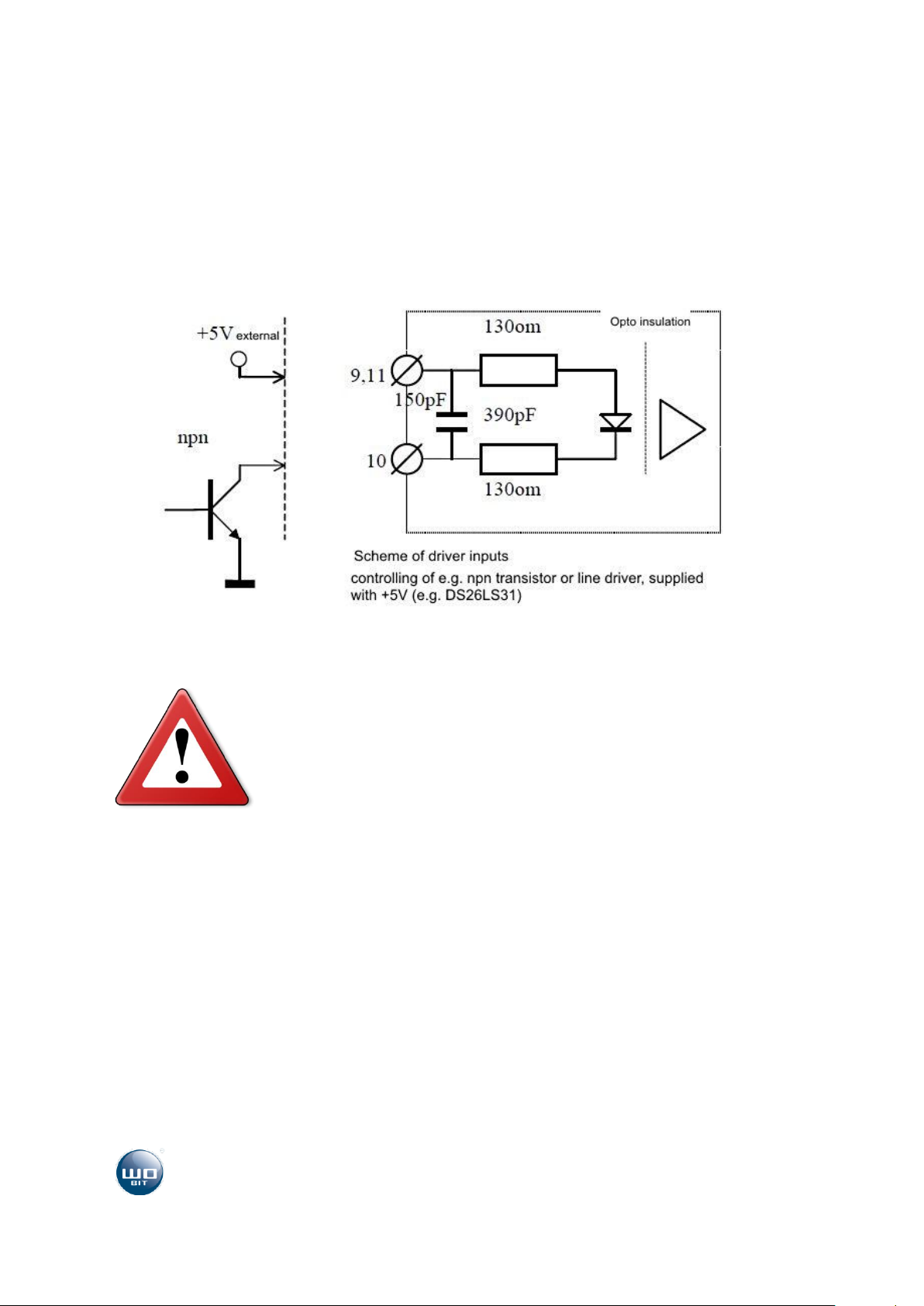
with a range of 0..5 V (given by e.g. PLC driver). Controlling of revolution direction is made by
optically insulated Dir input. Start input determines if motor is rotating or is stopped. To supply driver
you should use non-stabilized feeder, with external power supply equal to rated voltage of
connected motor. Feeder should have a large electrolytic capacitors on output for receiving returning
energy from a driver (BACK EMF). While connecting the driver pay attention to correct polarisation of
power supply, because conversion + with –will cause damage of the driver.
3. Features
-Direct current up to 6 A (temporarily up to 30 A)
-Wide range of power supply 10..24VDC
-Miniature power stage
-Transistors with static drain source on resistance 10m
-Controlling of power stage by PWM signal
-Regulation of fullness in full range (0-100%)
-Regulation of rotational speed by external potentiometer or by analogue signal 0..5V
-Optically insulated inputs
-LED indicator of error and operation state
-LED indicator of power supply
-Over current protection of power stage
-Thermal protection
-Protection against short-circuit of power stage
-Power supply and all controlling signals are placed on connectors with screw fastening PTR
type
-Housing is adopted for mounting on DIN rail

www.wobit.com.pl
Manual -SDC106 –27.10.2014 –v.1.1
page 5
3.1 Block diagram of the driver
3.2 Connectors description

www.wobit.com.pl
Manual -SDC106 –27.10.2014 –v.1.1
page 6
1, 2 –“minus” of supplying voltage 10..24VDC
3 - “plus” of supplying voltage 10..24VDC
4 - output for connecting dc motor
5 –output for connecting dc motor
6 - ground for potentiometer or analog controlling signal
7 - potentiometer slider, or input of analog signal 0..5 V
8 –5V for potentiometer (max. Load 50mA)
9 –positive electrode of transoptor controlling Dir input
10 –cathode (common for Start and Dir inputs)
11 - positive electrode of transoptor controlling Start input

www.wobit.com.pl
Manual -SDC106 –27.10.2014 –v.1.1
page 7
3.3 LED indicators description
Power –power supply (red diode)
Error –(yellow diode), blinks while occurring error
Ready –(green diode) is on while driver is ready
for operation
Start - operation (green diode) is on while motor
operation
Dir –direction (green diode), means operation in
opposite direction

www.wobit.com.pl
Manual -SDC106 –27.10.2014 –v.1.1
page 8
3.4 Inputs description
Start and Dir inputs are opt insulated and have internal resistors, which adopts them for direct
controlling of 5VDC voltage. Way of controlling is shown schematically on picture below.
Caution!
Do not use +5 V voltage available on driver clamps for supplying opt
insulation, because it cause galvanic short-circuit of input with opt
insulated output.
4. Operation description
Driver after connecting of power supply realizes initialization procedure of the device, which is
signalized by short blinking both of diodes (Ready and Error), after that the device is ready for
operation, which is signalized by activation Ready diode and deactivation Error diode. Giving a signal

www.wobit.com.pl
Manual -SDC106 –27.10.2014 –v.1.1
page 9
on Start input cause starting operation of the motor. Motor will be speed up to velocity given by
potentiometer. After reaching given speed value motor is rotating with constant speed, which can be
changed by user through change settings of the potentiometer. Disconnecting of the input (no signal)
cause stopping of the motor. Dir input is used for change direction of the motor rotation. When
change occurs while motor is rotating, it will be stopped and repeated speed up to given speed value
but in opposite direction.
Activation of whichever protection is signalized by blinking of Error diode and deactivation Ready
diode. Error diode will stops blinking and turns off and Ready diode turns on repeated signalizing
readiness of device for further operation.
Electrical data
Power supply
+10..+24 VDC
Max. rated current
6 A
Insulated inputs
2 (Start and Dir)
PWM frequency
7.8 kHz
Potentiometer resistance
5k- 50k
Supply indicator
Red LED
Operation temperature
0..+60C
Cooling
Gravitational
Mechanical dimensions
120x101x22.5 (housing)
Ordering symbol: SDC106
Table of contents
Other WOBIT DC Drive manuals
Popular DC Drive manuals by other brands

ABB
ABB DCS800 Hardware manual

ABB
ABB ACS580-07 Hardware manual

Leadshine Technology
Leadshine Technology M415B user manual

Newport
Newport New Focus 8712 user manual

ZIEHL-ABEGG
ZIEHL-ABEGG PMIcontrol Basic-M Series operating instructions

RHINO MOTION CONTROLS
RHINO MOTION CONTROLS RMCS-3002 operating manual