Schramm Master UM-200 User manual

OPERATION MANUAL
SLEEP SYSTEM BASE MATTRESSES
Master UM-200 | UM-201 |
UM-220 | UM-221
09/2016
11.V1

Radio remote control for motorised base mattresses
LED
Display
memory button 1 / 2 / 3
(preset programmable)
memory button 4 / 5 / 6
(programmable)
RESET (all down) functionless
functionless
clock
S.C.A. (optional) neutral
S.C.A. (optional) shoulder area
S.C.A. (optional) pelvis area
memory button / child proof lock
head / back
thigh /lower leg
Child proof lock activate: press button S for 8 secs: double beep
deactivate: press button Sfor 8 secs: single beep
Battery case on reverse: 3 batteries Type Micro AAA 1,5V (pls note polarity)
Fig. 1

Memory functions 1 - 6
If not already preset, the programming is performed as follows:
- Use buttons and (below the flap of the remote control) to set the desired resting position.
- Press button S 3 times
- Press any of the memory buttons 1 - 6
- Setting is confirmed by a beep. Memory position appears on the display.
- Any preset position will be overwritten.
- The optional S.C.A. setting will not be affected by this change.
Teaching a new remote control
If a new remote control is to be used for a new system, this motorised bed’s controller unit has to be “taught” how
to communicate with the new remote control.
- Press any button 1-6 of the remote control (LED flashing)
- Keep button pressed while switching the rocker switch of the controller unit (Fig. 2). A successful teaching is
confirmed by a beep.
- Press Sbutton 3 times and keep RESET button pressed until all motors finished the reset (confirmed by
double beep).
- System is ready for operation.
The controller is located under the movable lower leg section, the rocker switch is either directly accessible from the
bottom or after lifting the foot section.
Teaching may be repeated as often as desired and for different remote controls. Every remote control operates with
an individual frequency which is unique, the controller unit picks up on this particular frequency during teaching.
Fig. 2
Control
sync cable
SHIFT
pelvic S.C.A.
rocker switch
S.C.A. shoulders
thigh
back

Synchronisation
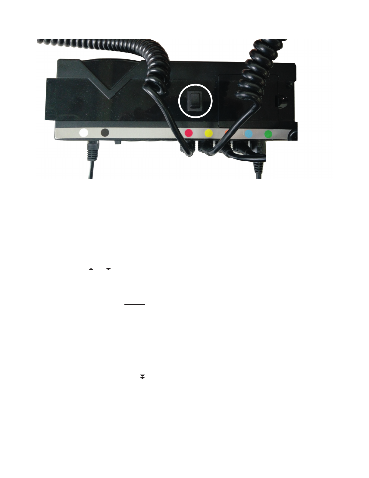
The controller units of two identical motorised base mattresses are connected with each other by a sync cable (Fig. 2,
controller). Each of the two base mattresses boasts its own remote control.
With this configuration both base mattresses adjust synchronously no matter which remote control is used for setting.
The controller units also recognize different weights and coordinate the movement in a way that both sides of the bed
are set in an almost identical position. The S.C.A. adjustment is exempt from this synchronisation and may be ad-
justed individually by the corresponding remote control. If two synchronised systems are separated by removing the
sync cable both systems have to be initialised anew. This is achieved as follows:
- Press button S3 times
- Press button RESET and keep pressed. All motors move towards their mechanical terminal point, the
controller unit confirms by a double beep, when finished.
- Release button, the system is operable again.
The same procedure applies to the partner system. This initialization will also make the S.C.A. motors move all the
way down. Please reset the S.C.A. to the desired position afterwards.
For restoring the synchronisation later it is sufficient to reconnect both systems by the sync cable.
All down
By using the button RESET / All down you set the motorised base mattress into the initial lowered horizontal posi-
tion. All parts move at the same time. S.C.A. settings will not be affected.
Time
Set the time on the display as follows:
- Press button for 2 secs, the hour display will start to flash.
- Select the desired hour by pressing the + / - keys.
- Briefly press button , the minute display will start to flash.
- Select the desired minute by pressing the + / - keys.
- Briefly press button to confirm.
S.C.A. - Secondary Contour Adaptation (optional feature)
To optimise the sleep position the corresponding sections in the shoulder and pelvic areas may be shifted by 2 cm up
or down from the neutral central position.
Upon pressing one of the buttons for adjusting S.C.A. shoulder or S.C.A. pelvis , the corresponding symbol
will appear to the right of the display next to the bar diagram (see fig. 2, page 2).
The filled bars display the last set position, indicating the neutral central position by -0-.
To adjust press the button up or down until the desired position has been reached, the maximum being the up-
per or lower terminal point. During this operation the bar diagram will continuously show the current position.
Adjustment by one bar corresponds to a height difference of app. 5 mm while briefly tapping the button will adjust by
app. 2 mm.
After confirmation the display will remain activated for app. 10 secs unless you select any other operation.
The neutral central position of both S.C.A. ranges may be selected by the N button. Press this button until the adjust-
ment has been finished while both S.C.A. motors move to the neutral position at the same time.
If the reception of the transmitter signal is disturbed during an S.C.A. adjustment due to unfavourable circumstances
adjustment will not be performed although the bar display indicates otherwise. Upon the next transmitter operation
for adjusting the S.C.A. position the base mattress will be correctly set according to the transmitter’s display.
The SHIFT function (optional feature)
The electronic control of a motorised base mattress which is equipped with a SHIFT function will make the whole
base mattress slide up to 25 cm towards the back whenever there is an upward movement of the rear section. Upon
lowering the base mattress this process will be performed vice versa.

Emergency lowering
Even in the event of a power failure the base mattress can be moved back to the horizontal resting position thanks to
the integrated batteries. The rocker switch is to be found on the controller unit which is located in the middle of the
foot end of the motorised surface. According to bed type and set position the rocker switch may either be accessed
from below the bed or after lifting the foot end.
Keep the switch pressed down until all motors have moved back. If necessary, keep the foot section lifted; once the
emergency lowering is finished, put the foot section back into its horizontal position. As soon as electricity is available
again you will be able to instantly adjust the setting of the base mattress as usually. In case the emergency lowering
process will only be performed partly or not at all, the 9V batteries of the controller unit were not sufficiently charged
anymore and require replacement by new ones. Also, the batteries should be replaced after any emergency lowering
procedure.
Torch function
The torch LED illuminates upon pressing the large button. If the button is pressed for 2 secs until the red function
LED stops flashing the torch LED will automatically stay on for 10 more seconds.
Mains disconnection
As a standard, the motorised base mattress is equipped with a mains disconnection in the plug. The 220V mains
voltage will only be activated when the remote control is operated (audible click, green LED lights up). The LED extin-
guishes a few seconds after the adjustment procedure has been completed. In idle mode only a low voltage control
current is maintained so that the controller may detect and process incoming signals.
Cleaning and care of your sleep system
Special attention must be paid to the fact that improper stresses such as sitting on the foot or head section while
raising the bed or when raised may jeopardize the system.
Continuous adjustment operation may lead to overstressing the drive motor. An uninterrupted adjustment of the base
mattress for more than two minutes therefore must be avoided. We accept no liability for any corresponding damage
having occurred due to inobservance of this instruction. Upon pulling the plug, never pull the cables to protect the
connection from excessive tensile stress. Heavy objects must not be put on top of the cables. The cables are also
to be protected from exposure to heat (radiators, hot air fans, etc.) There are two 9V batteries in the controller unit
beneath the lower leg section providing sufficient energy for an emergency lowering procedure. If this procedure is
not performed, the batteries will last for app. 3 years; however, if the emergency lowering is performed only once, the
battery will be used up. Please provide for replacement batteries in due time.
Caution!
When working on the technical equipment of your sleep system – e.g. while remedying malfunctions – always pull
the mains plug.
Service
If you require assistance by a qualified customer service technician in case of malfunction or damage please contact
your retailer who will instantly provide any expertise and help you may need.
Enjoy your new bed and have a restful sleep.

Troubleshooting
Please note the following potential malfunctions and their elimination. If you are unsure what might have caused the
malfunction we recommend you to check the individual points or take the recommended steps in the indicated order.
No function, no reaction at all
- Check whether the mains plug has been correctly inserted into the socket.
- Check the batteries in the remote control for correct polarity, contact and state of charge. Upon pressing the
buttons, the red function LED and the torch are supposed to light up. If necessary, please replace batteries.
- Check the communication coding of motorised base mattress and remote control. If necessary teach the
controller unit to the remote control like described in “Teaching a new remote control”.
Still no function, but beeps from the controller unit of the base mattress
- Check the child proof lock. Press button S for app. 8 secs until a beep occurs. If it was a single beep, the child
proof lock was deactivated (see above) and you may now check the function of the base mattress. If you hear
a double beep, the child proof lock has just been activated. To deactivate it again, press the button S once
more for 8 secs until you hear a single beep. Now check the base mattress function.
Adjustment cannot be performed for the entire range
- Check whether the adjustment mechanism of the base mattress can move freely

EG-KONFORMITÄTSERKLÄRUNG
Erzeugnis: Elektromotorisch angetriebene
Untermatratze in Boxspringbetten
Typenbezeichnung: EP-Untermatratzen
Hersteller: Schramm Werktätten GmbH,
Winnweiler
Das bezeichnete Erzeugnis stimmt mit den Anforderun-
gen folgender europäischer Richtlinien überein:
Maschinenrichtlinie
98/37EG
Niederspannungsrichtlinie
73/23/EWG; 93/68/EWG
EMV-Richtlinie
89/336/EWG; 92/31/EWG, 93/68/EWG
EMF-Richtlinie
2013/35/EU
Grundlage
Prüfbericht Nr. S 60077880
Prüfbericht Nr. RT 60042790
Prüfbericht Nr. RT 60042791
TÜV Product Safety GmbH
Axel Schramm
DECLARATION OF CONFORMITY
Product: Electric motor-driven base
mattress for boxspring beds
Model: Base mattress
Manufacturer: Schramm Werktätten GmbH, Winnweiler
The described product is in accordance
with the requirements of the following
European directives:
Machinery directive
98/37EG
Low voltage directive
73/23/EWG; 93/68/EWG
EMC directive
89/336/EWG; 92/31/EWG, 93/68/EWG
EMF directive
2013/35/EU
Basic
Test report No S 60077880
Test report No RT 60042790
Test report No RT 60042791
TÜV Product Safety GmbH
Axel Schramm

Attention!
This appliance is not intended for use by persons (including children) with restricted physical, sensory or
mental abilities or with a lack of experience and/or knowledge, unless supervised by a person responsible
for their safety or after having been instructed by said person as to the operation of the appliance.
Children must be supervised in order to ensure that they do not play with the appliance.
Always pull out the mains plug if work is to be carried out on the sleep system technology - e.g. to rectify
malfunctions.
Schramm Werkstätten GmbH
Am Stundenstein 1
D-67722 Winnweiler
Tel.: ++49-6302-9236-0
Fax: ++49-6302-9236-99
info@schramm-werkstaetten.de
www.schramm.ag
!
This manual suits for next models
3
Table of contents
Popular Indoor Furnishing manuals by other brands

WB Mfg
WB Mfg Flip Top Assembly instructions

Presidential Billiards
Presidential Billiards KARIBA installation instructions

J.Burrows
J.Burrows JB5TMTLSWE Assembly instructions

Philips
Philips Colourful Lights Specifications

Furn Mill
Furn Mill HOBED00076 Assembly instruction

Vivo
Vivo DESK-V001KE instruction manual

Home Decorators Collection
Home Decorators Collection JS-3427-C Use and care guide

Manatee
Manatee r82 manual

Furniture of America
Furniture of America Northvale CM3888T-5PK Assembly instructions

Astonica
Astonica 50105624 instruction manual

Argos
Argos Amersham 881/4968 Assembly instructions

Round Hill Furniture
Round Hill Furniture B138NQ Assembly instruction