Schwamborn WDS 250 Operation manual

EN Wall, ceiling and floor grinding machine WDS 250
Translation of the original operating manual
WDS250‐en‐220909

EN Wall, ceiling and floor grinding machine WDS 250
WDS250‐en‐220909
2
Manufacturer: Schwamborn Gerätebau GmbH
Robert‐Bosch‐Straße 8
D‐73117 Wangen / Göppingen
Telephone: +49 (0)7161 2005‐0
Telefax: +49 (0)7161 2005‐10
E‐mail:
URL:
www.schwamborn.com
Document: WDS 250 en
Publishing date: 9.9.2022
Contents
1 Important information 3........................................................
1.1 Symbols used 3...........................................................................
1.2 Copyright, liability and warranty 3............................................................
1.3 Definition of terms 4.......................................................................
2 Safety 5......................................................................
2.1 Accident prevention and safety 5............................................................
2.2 Safety instructions 5.......................................................................
3 Operating 7...................................................................
3.1 Putting the grinding machine into operation 7.................................................
3.2 Operation 9...............................................................................
3.3 Ending the operation 11.....................................................................
4 Maintenance 12................................................................
4.1 Coupling/Uncoupling the guide arm 12........................................................
Coupling the guide arm 12....................................................................
Uncoupling the guide arm 13..................................................................
4.2 Adjusting the angle between grinding machine and guide arm 14.................................
4.3 Swivel the grinding head 15..................................................................
4.4 Mounting and dismantling the tools 15........................................................
Mounting and dismantling ETX diamond tools 16................................................
4.5 Check / replace dust protection 16............................................................
4.6 Working on hydraulic components 17.........................................................
4.7 Cleaning the grinding machine 17............................................................
4.8 Final tasks 17..............................................................................
5 Accepting the grinding machine 18...............................................
6Transport 18...................................................................
6.1 Separate the grinding head from the grinding machine 18........................................
6.2 Transporting the grinding machine 19.........................................................
7 Customer service and spare parts 20.............................................
8 Declaration of conformity 20.....................................................
9 Troubleshooting 21.............................................................
10 Technical data 22.............................................................

Warning Prohibition Direction
n
1 Important information
EN Wall, ceiling and floor grinding machine WDS 250
WDS250‐en‐220909
3
1 Important information
The grinding machine may be used only with the ac‐ cessories
supplied by the manufacturer for stripping and grinding of even
wall and ceiling surfaces or even floor surfaces such as:
—concrete
— natural stone
—plaster
— residual adhesive or filling compound
—paint
Any other use of the grinding machine can lead to endanger
ment and is prohibited!
To ensure proper use of the machine, follow the instructions in
the operating manual, paying particular attention to any
warnings and instructions relating to operation and maintenance!
Before using the grinding machine, this operating
manual must be carefully read and understand
by the operator!
Keep this operating manual close at hand for
easy reference!
Read and observe operating manuals for the guiding machine
provided by suppliers!
If the grinding machine is loaned to other parties, the operating
manual needs to be provided with the machine and its
importance must be made clear!
1.1 Symbols used
The following symbols are used in this documentation:
Safety instructions
This symbol indicates warnings, prohibitions and instructions
regarding potential hazards. These instructions must be obeyed
and closely observed.
Some safety instructions are accompanied by corresponding
symbols.
Additional information
This symbol indicates additional information.
GG" Important text
Precondition or consequence of an activity
7. Instruction
The order of the actions must strictly
be adhered to,
!Reference to text passages or figures

1 Important information
EN Wall, ceiling and floor grinding machine WDS 250
WDS250‐en‐220909
4
1.2 Copyright, liability and warranty
Schwamborn Gerätebau GmbH
All rights, including related translations, belong to the
Schwamborn Gerätebau GmbH.
Any reproduction, use or distribution of this original operating
manual or its translations, in whole or in part, is prohibited with
out the express written permission of Schwamborn Gerätebau
GmbH.
Liability or warranty is excluded if:
—The instructions in the operating manual have not been
observed.
—The grinding machine or its attachments were improperly
operated.
—The maintenance was carried out inadequately or incor
rectly.
—Specified original spare parts were not used.
—The protective equipment was not used, has been altered
or was removed.
—The specified power supply ratings and surrounding condi
tions have not been observed.
—The tool speed has been set too high
(!Chapter 3.2, Pos. 4., Page 9).
—An unsuitable dust extraction has been used.
The manufacturer recommends using suction devices with
a suction capacity of approx. 500 m3/h ... 2200 m3/h.
The manufacturer is not liable for any damage that may result if
the user makes any changes to the grinding machine without the
permission of Schwamborn Gerätebau GmbH. Any such actions
will void the warranty.
1.3 Definition of terms
Grinding machine
The wall, ceiling and floor grinding machine
WDS 250 is referred to in this operating manual as grinding ma
chine.
Guiding machine
The machine from which the wall, ceiling and floor grinding ma
chine WDS 250 is guided is referred to in this operating manual
as guiding machine. The guiding machine should be provided by
the customer.
The illustrations in this operating manual show a guiding
machine made by the manufacturer "Brokk" as an example.
The guiding machine types from size B70 of Brokk are com
patible with grinding machine WDS 250.
Coupling element
The machine part by which the grinding machine is coupled me
chanically to the guiding machine is called a coupling element in
this operating manual.

2 Safety
EN Wall, ceiling and floor grinding machine WDS 250
WDS250‐en‐220909
5
2 Safety
This chapter contains a summary of the most important
information on safety when handling the grinding machine.
2.1 Accident prevention and safety
The following instructions comply with legislation, directives and
publications such as:
—EC Machinery Directive
—EC Product Liability Directive
— EC Technical Documentation Directive
— Law on technical materials
—Law on equipment safety
—Law on product liability
This operating manual is intended for operators and tool setters,
as well as for the personnel that service, maintain and repair the
grinding machine. Together with all the technical documentation,
it is intended to help
—avoid hazardous situations
—use as intended
—avoid downtime and repair costs
—maintain the function of the grinding machine
—increase the service life of the grinding machine
The manufacturer and owner of the grinding machine must
observe the contents and provisions of the EC directives. The
effectiveness of any measure ultimately depends on how well all
parties, i.e. the manufacturer, the owner and the machine opera
tors, work together to uphold safety standards.
All laws and regulations (e.g. the valid regulations on waste
disposal), accident prevention guidelines and generally
recognised safety rules must be complied with when working on
and with the grinding machine.
2.2 Safety instructions
This grinding machine incorporates state of the art technology and
has been built in accordance with recognised safety regulations.
This ensures that the highest possible standards of occupational
safety are maintained. However, incorrect use of the grinding ma
chine could endanger the health and lives of the personnel or
cause material damage.
The grinding machine may only be operated by people who
have been assigned to do so and who have the appropriate
training and skills!
If any defects are found in the grinding machine that could
endanger people or damage property, stop the machine
immediately and ensure that it cannot be used again until
all repairs are completed.

@@@@2.2.1
2 Safety
EN Wall, ceiling and floor grinding machine WDS 250
WDS250‐en‐220909
6
The operating personnel responsible for the grinding
machinemustensurethatnoonecanenterthegrinding
machine’s danger zone during operation!
The safety distance during operation must be at least 10 m.
Risk of injury if safety equipment has been removed or is
non‐functional!
The safety equipment must be checked for completeness
and function before starting up!
The safety equipment must be in place during operation!
The surfaces to be ground by the grinding machine must
be free of obstacles and free of loose objects, which could
be flung out during grinding.
The grinding machine must be switched off immediately if
heavy vibrations or unusual noises occur during operation
so that cause can be removed.
Risk of injury from rotating grinding machine parts!
Limbs and clothing can be drawn in!
Proceed with the greatest care and caution!
Any work required for the hydraulic system may only be
performed by technicians with the requisite levels of
qualification.
Risk of poisoning due to harmful substances at the
workplace!
Eating, drinking or smoking at the workplace is prohibited!
Always eat in break rooms or canteen areas!
After completing the work, thoroughly clean yourself!
A general inspection of the machine must be conducted
before starting up the grinding machine! Particular attention
should be paid to damaged or loose components, and
wear! The grinding machine may only be put into operation
if it is in perfect technical condition!
Attachments and modifications to the grinding machine
which may affect the operational safety are prohibited!
Place the grinding machine with the supporting feet on a
level, horizontal floor with adequate load capacity (e.g. pal
let or floor) (!Fig.)!
Cleaning and maintenance may be done only by trained
personnel!
Maintenance must be conducted according to the operation
manual and maintenance plan!
Do not operate the grinding machine in areas where there
is risk of explosion or where flammable materials are
present.

3Operating
EN Wall, ceiling and floor grinding machine WDS 250
WDS250‐en‐220909
7
3 Operating
Risk of injury from parts flung out during grinding!
Wear protective clothing and protective goggles!
Wear safety shoes!
Wear protective gloves!
Proceed with the greatest care and caution!
Danger of injury from loud noise during grinding operation
of the grinding machine!
Always wear hearing protection when the grinding machine
is in operation!
Risk of injury from dust formation during grinding work!
Wear respiratory protection!
A suitable dust suction unit has to be connected to the
grinding machine. The manufacturer of the grinding
machine can gladly provide corresponding
recommendations.
The manufacturer recommends using suction devices with
a suction capacity of approx. 500 m3/h ... 2200 m3/h.
The manufacturer of the grinding machine can gladly
provide corresponding recommendations.
3.1 Putting the grinding machine into operation
Observe the safety instructions in Chapter 2, Page 5!
The initial start‐up of the grinding machine may be carried
out only by qualified personnel!
Observe the instructions on the guiding machine for the
operating temperature of the hydraulic fluid (ideally 30 -
75°C). That means a start-up phase is necessary for hea
ting up the hydraulic oil. A drop in machine performance is
possible during this phase.
When the grinding machine is commissioned for the first
time, the start-up phase is extended by the initial running-in
of the drive unit.
A visual inspection of the grinding machine needs to be
done before starting up the grinding machine.
Particular attention should be paid to damaged or loose
components, and wear!
Always use suitable grinding tools or abrasive bonding for
the surface to be machined. The manufacturer of the
grinding machine can gladly provide corresponding
recommendations.
1. Checkthesurfacetobegroundandremoveanyprotruding
objects and metal parts.

19
6
13
12
A1...A4
A4
A2
A3
A1
The figures show an example of a guiding
machine from the manufacturer "Brokk".
16
6
7
16
Wall
Guide arm
Grinding machine Guiding machine
3Operating
EN Wall, ceiling and floor grinding machine WDS 250
WDS250‐en‐220909
8
2. Turn the grinding machine in the direction of the guide arm
[19] and place with the supporting feet [13] on a level, hor
izontal floor with adequate load capacity (e.g. pallet or
floor) (!Fig. on page 6).
3. Check tools for function and condition and replace if neces
sary (!Chapter 4.4, Page 15).
4. Connect the 4 hydraulic connections [A1...A4] between the
guide arm and the grinding machine.
The hydraulic couplings on the guide arm and on the grin
ding machine have different sizes and markings and must
not be mixed up.
GG" For wall grinding the grinding machine must be turned by
90° and for floor grinding by 180°!
5. If necessary adjust the angle between grinding machine
and guide arm (!Chapter 4.2, Page14).
6. Swivel the grinding head to the required position
(!Chapter 4.3, Page 15).
7. Connect the suction hose to the dust extraction connection
[16] and guide it with the Velcro straps on the grinding ma
chine (if necessary, move the Velcro strap [7] as required).
Depending on requirements, a maximum of 2 hoses can be
connected to the connections for dust suction [16].
The manufacturer recommends using suction devices with
a suction capacity of approx. 500 m3/h ... 2200 m3/h.
GG" Connections to the dust suctions that are not used have to
be closed with the corresponding caps!
GG" For wall grinding, the guiding machine
with the guide arm must be parallel to
the wall (!Figure)!
8. Coupling the guide arm to the machine
(!Chapter 4.1, Page 12).
9. Liftthegrindingmachinewiththe
guide arm and move the guiding ma
chine into the working position.
10. Check the safety equipment for
completeness and function before
starting up!

42
5
3Operating
EN Wall, ceiling and floor grinding machine WDS 250
WDS250‐en‐220909
9
3.2 Operating
The grinding machine was put into operation
(!Chapter 3.1, Page 7).
Risk of injury from inadvertent starting and movement of
the grinding machine or guiding machine!
Risk of injury from loose parts!
During operation, loose parts (stones / removed material /
broken components / tools etc.) can be flung out!
Keep at least 5 m safety distance from the grinding ma
chine and from the guiding machine!
The operating and maintenance personnel responsible for
the grinding machine must ensure that no one can enter
the grinding machine’s danger zone during operation or
maintenance work!
Risk of injury and fire hazard from hot surfaces on the ma
chine housing, tool mounts and grinding tools!
Wear protective gloves!
Have suitable fire extinguishers on hand!
Work with the greatest care and caution!
The dust cover ring must always contact the surface being
machined during operation (!Chapter 4.5, Page 16)!
GG" The manufacturer of the grinding machine urgently recom
mends practising the grinding of walls, ceilings and floors
sufficiently.
1. Switch the guiding machine on.
When the grinding machine is switched on at the controller of
the guiding machine, the contact pressure of the grinding
machine head is applied by the hydraulic control system and
is not operated via operating elements of the guiding
machine.
Risk of injury from rotating machine parts!
Work with care!
2. Switch on the tool rotation and the contact pressure using
the remote control of the guiding machine
(!operating manual of the guiding machine, chapter
Operation of double‐acting hydraulic tools
).
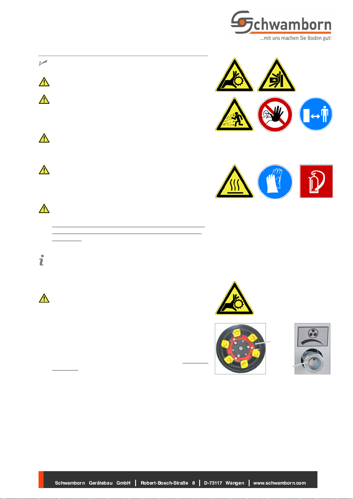
3. Measure the speed of the gear disc [42] with a suitable mea
suring instrument.
GG" The maximum speed of the gear disc was set to maximum
2000 rpm when the guiding machine was adapted to the
grinding machine. This preset hydraulic volume flow of the
guiding machine may not be changed!
When the guiding machine is changed, the maximum speed
must be reset to 1800 rpm .... 2000 rpm.
4. Use the controller [5] to set the desired gear disc speed if
necessary.The manufacturer of the grinding machine can
gladly provide corresponding recommendations.

46
45
47
23
Max Min
+6° ‐6°0°
48
3Operating
EN Wall, ceiling and floor grinding machine WDS 250
WDS250‐en‐220909
10
5. Set the contact pressure:
The contact pressure [46] is created in the grinding
machine from the supply pressure and in its delivery
condition is approx. 20 bar, that corresponts to a con
tact force of approx. 900 N.
The set contact pressure is in the entire extension
range constant.
GG" The contact pressure may only be changed using the
controller [45]!
For the required contact pressure, the manufacturer of
the grinding machine gives corresponding recommen
dations on the "Contact Pressure" information plate
(!Figure).
Set the required contact pressure by slowly turning the con
troller [45] and observing the pressure display [46].
GG" The service flap [47] covers the counter-pressure con
troller. The counter pressure may only be changed by
authorised personnel!
6. Switch off the tool rotation and the contact pressure using
the remote control of the guiding machine.
7. Move the grinding machine head with the grinding tools
into work position (!Fig. on page 8, Pos. 9.)
GG" During the grinding process, the indicator [24] should al
ways be between the minimum value (0 mm) and the maxi
mum value (200 mm).
The grinding machine head is moved by the guide arm and
the travel motion of the guiding machine.
The grinding machine head adjusts itself to the angle of the
surface vertically and horizontally by maximal ±6° (!Fig.).
GG" This tilt angle (±6°) should not be exceeded, because
otherwise the grinding tool does not contact completely
with with the surface to be machined and causes
imperfections.
GG" The tilt angle should be checked regulary with the incli
nometer [48].
Theangleisdisplayedin1°stepsandin5°steps.
The inclinometer can be rotated 90° for floor and ceiling
operation.
8. Switch on the tool rotation and the contact pressure using
the remote control of the guiding machine.
The surface to be ground can now be machined.

23
Min
16
16
A4
A2
A3
A1
19
6
13
12
A1...A4 The figures show an example of a guiding
machine from the manufacturer "Brokk".
3Operating
EN Wall, ceiling and floor grinding machine WDS 250
WDS250‐en‐220909
11
3.3 Ending the operation
Observe the safety instructions in Chapter 2, Page 5!
The drive and the position of the grinding machine head is con
trolled by the operating elements of the guiding machine.
Risk of injury from grinding tools still rotating after the grind
ing machine is switched off!
Thetoolholderdisccancontinuetoturninidle(run‐on) for
several seconds after switch off!
Risk of injury from moving the grinding machine or the gui
ding machine!
Keep a safe distance!
1. Switching off the grinding machine head
(!operating manual of the guiding machine).
The contact pressure is relieved.
The grinding machine head is moved to starting
position [0] (!Fig.).
2. Place the grinding machine with the supporting feet on a
level, horizontal floor with adequate load capacity (e.g. pal
let or floor). (!Fig. on page 6).
3. Either
If the grinding machine is to be used further (e.g. after a
break):
— Switch the guiding machine off.
4. or
If the grinding machine [12] is not to be used further:
a. Unlock the guide arm [19] and disconnect from the
coupling element [6] (!Chapter 4.1, Page 12).
b. Switch the guiding machine off.
c. Separate the 4 hydraulic connections [A1...A4].
d. Disconnect the suction hose from the dust suction
connection [16].

46
19
8
4 Maintenance
EN Wall, ceiling and floor grinding machine WDS 250
WDS250‐en‐220909
12
4 Maintenance
Observe the safety instructions in Chapter 2, Page 5!
The operating and maintenance personnel responsible for
the grinding machine must ensure that no one can enter
the grinding machine’s danger zone during operation or
maintenance work!
Maintenance work may only be performed by trained spe
cialists! They must be familiar with the dangers associated
with such work, protect themselves and avoid danger!
When working on the grinding machine (set‐up,
maintenance, tool change, service, repair, cleaning, etc.),
the guiding machine has to be switched off by pressing the
EMERGENCY STOP button and has to be disconnected
from the power supply.
Risk of injury from residual pressure in the hydraulic
system of the grinding machine after separating the hy
draulic connections! This can lead to uncontrolled move
ments. Wait before continuing work until the hydraulic is
depressurised
(observe the contact pressure display [46])!
Perform maintenance and cleaning work in accordance
with the maintenance plan and operating manual and
check the safety equipment for completeness and function
ality.
4.1 Coupling/Uncoupling the guide arm
4.1.1 Coupling the guide arm
This operating manual shows the coupling to a guiding ma
chine made by the manufacturer "Brokk" as an example.
Danger of being crushed!
Work with the greatest care and caution!
Risk of injury from falling grinding machine!
Establish coupling and securing carefully
Keep at a safe distance.
1. Place the grinding machine with the supporting feet on a
level, horizontal floor with adequate load capacity (e.g. pal
let or floor) (!Fig. on page 6).
GG" The coupling elements of the mounting plate must be posi
tioned with the upper fastening hooks [8] in the direction of
the guide arm [19] (→ Fig.).
Risk of injury and damage!
Thegrindingmachinemayonlyberaisedoncetheguide
arm has been properly coupled and secured.

1.
2.
3.
6
19
8
@@@@4.1.3
4 Maintenance
EN Wall, ceiling and floor grinding machine WDS 250
WDS250‐en‐220909
13
2. Switch the guiding machine on.
3. Use the guide arm [19] to move the forward pin into posi
tion "1.".
4. Use the guide arm to move the rear pin into position "2."
until the elbow joint "3." latches in.
5. Switch the guiding machine off.
6. Insert the securing element A [28].
7. Insert securing element B [29] and beat tight with a ham
mer [30].
8. Insert the securing spring [31] through both securing
elements (A/B).
A
28
B
29
30
31
4.1.2 Uncoupling the guide arm
GG" To uncouple the guide arm, proceed in the reverse order
(!Chapter 4.1.1, Page 12).
1. Place the grinding machine with the supporting feet on a
level, horizontal floor with adequate load capacity (e.g. pal
letorfloor)(!Fig.).
2. Pull out the securing spring [31].
3. Remove the securing element B [29]
(use a hammer if necessary).
4. Remove the securing element A [28].
5. Switch the guiding machine on.

1.
2.
3.
6
19
19
12
9
The figures show an example of a guiding
machine from the manufacturer "Brokk".
922
21
20
4 Maintenance
EN Wall, ceiling and floor grinding machine WDS 250
WDS250‐en‐220909
14
6. Unlatch the elbow joint ("1.")
(use a hammer if necessary).
7. Use the guide arm [19] to move the rear pin towards "2.".
1. Use the guide arm [19] to move the front pin towards "3.".
2. Remove the guide arm.
3. Switch the guiding machine off.
4.2 Adjusting the angle between grinding machine and guide arm
The guide arm [19] is coupled with the 2 coup
ling elements [6] (!Chapter 4.1, Page 12).
1. Switch the guiding machine on.
GG" The grinding machine has to be in horizontal position!
2. Swivel the grinding machine with the guide arm into hori
zontal position (!Fig.).
3. Switch the guiding machine off.
The guiding machine must not be operated up to pos. 7!
Increased danger of crushing hands and feet!
Wear safety shoes!
Wear protective gloves!
For safety, the grinding machine should "hover" close to
the ground during angle adjustment.
Work with the greatest care and caution!
4. Loosen (do not screw out) the 4 clamping elements [22]
andfolddown(!Fig.).
GG" The central screw [21] must not be unscrewed!
The grinding machine is connected to the locating plate [9]
only by the screw [21] and can be rotated.
For wall grinding the grinding machine must be turned by
90°.
5. Turn the grinding machine into the desired position
(steps of 22.5°).
6. Fold the 4 clamping elements [22] upwards into the corre
sponding recess [20] and screw tight. (!Fig.).
7. Switch the guiding machine on.
8. Place the grinding machine with the supporting feet on a
level, horizontal floor with adequate load capacity (e.g. pal
let or floor). (!Fig. on page 6).
9. Switch the guiding machine off.

54 55
53
n
Forabetteroverview,the
hydraulic hoses are not shown.
Examples
4 Maintenance
EN Wall, ceiling and floor grinding machine WDS 250
WDS250‐en‐220909
15
4.3 Swivel the grinding head
The grinding head can be swivelled for grinding close to the
edge (Wall Floor or Wall ceiling).
Wear safety shoes!
Wear protective gloves!
1. Ending the operation (!Chapter 3.3, Page 11).
2. Place the grinding machine with the supporting feet on a
level, horizontal floor with adequate load capacity (e.g. pal
let or floor). (!Fig. on page 6).
Risk of injury from sudden swivelling of the grinding head!
Hold the grinding head firmly!
3. Unscrew the 4 screws [54] on the swivel plate [53].
The grinding machine is now only connected to the grinding
head via the central screw [55] of the swivel plate and can
be swivelled.
4. Swivel the grinding head to the required position (examples
→Fig.)andfastenittotheswivelplatewiththe4screws
[54].
4.4 Mounting and dismantling the tools
Risk of injury!
Wear protective gloves!
Risk of damage due to unsuitable tools!
The manufacturer strongly recommends using only the cer
tified tools offered by the company Schwamborn Gerätebau
GmbH.
1. Place the grinding machine with the supporting feet on a
level, horizontal floor with adequate load capacity (e.g. pal
let or floor). (!Fig. on page 6).
2. Switch the guiding machine off.
The consistency of the surface to be ground determines the
type or the composition of the tools to be used.
The manufacturer of the grinding machine can gladly
provide corresponding recommendations.

3736 38 39
40
171
3...8 mm
4 Maintenance
EN Wall, ceiling and floor grinding machine WDS 250
WDS250‐en‐220909
16
Mounting and dismantling ETX diamond tools
All ETX diamond tools authorised for this grinding machine
are dismantled and mounted in the same manner.
GG" All ETX carriers have to be equipped with diamond tools of
the same type and the same quantity (always 9 tools). The
manufacturer of the grinding machine can gladly provide
corresponding recommendations.
Thediamondtoolsneedtobeequalinheight(wear level).
Dismantling ETX diamond tools
1. Loosen (do not screw out) the 3 retaining screws [36].
2. Turn the red retaining ring [39] anti-clockwise ↺until the
ETX diamond tools have been released.
3. Gently tap with a lump hammer to loosen the ETX diamond
tools [37] from the ETX- carrier [38] and then remove.
Mounting ETX diamond tools
1. Insert new ETX diamond tools into the recess [40] of the
ETX-carrier and press firmly (use lump hammer if neces
sary).
2. Turn the retaining ring clockwise ↻until the ETX diamond
tools have been clamped in.
3. Tighten the 3 retaining screws [36].
4.5 Check / replace dust protection
GG" Thebrushstrip[1]shouldextend3...8mmbeyondthe
grinding tools.
—Check the brush strip for condition, proper position and
function and, if necessary, replace or adjust.
Replace brush strip
1. Remove the worn brush strip [1].
2. Push the new brush strip firmly and evenly onto the suction
ring [17].
The fit of the brush strip can only be checked if the ETX
diamond tools are properly mounted
(!Chapter 4.4, Page 15).
3. To check, place a straight, long enough object (e.g. water
level, rod) on the brush strip [1].
4. The distance between the straight object and the ETX dia
mond tools should be 3 ... 8 mm (!Fig.).

19
13
12
A1...A4
The figures show an example of a guiding
machine from the manufacturer "Brokk".
16
16
A4
A2
A3
A1
4 Maintenance
EN Wall, ceiling and floor grinding machine WDS 250
WDS250‐en‐220909
17
4.6 Working on hydraulic components
All work on the hydraulic components of the grinding ma
chine may only be carried out by suitably knowledgeable,
qualified professional technicians!
4.7 Cleaning the grinding machine
Risk of damage!
Do not use high pressure cleaners or compressed air to
clean the grinding machine! Wear protective gloves!
1. Place the grinding machine with the supporting feet on a
level, horizontal floor with adequate load capacity (e.g. pal
let or floor). (!Fig. on page 6).
2. Switch the guiding machine off.
3. After operation, clean the grinding machine and the tools
dry with a brush, a cloth and vacuum cleaner.
4.8 Final tasks
Either: Restart the grinding machine
(!Chapter 3.1, Page 7).
or shut the grinding machine down:
a. Place the grinding machine [12] with the supporting
feet [13] on a level, horizontal floor with adequate load
capacity (e.g. pallet or floor).
b. Uncouple the guide arm
(!Chapter 4.1, Page 12).
c. Pull off and remove the hose of the dust extraction
from the connection to the dust extraction [16].
d. Separate the 4 hydraulic connections [A1...A4] from
the grinding machine and/or the guide arm.
e. Securely attach the hydraulic lines to the grinding ma
chine or guide arm.
GG" The hydraulic connections need to be protected against
soiling.
GG" For longer periods in transport or in storage, the grinding
machine needs to be covered to protect it against soiling.

54 55
53
52
n
5Accepting the grinding machine
EN Wall, ceiling and floor grinding machine WDS 250
WDS250‐en‐220909
18
5Accepting the grinding machine
Observe the safety instructions in Chapter 2, Page 5!
The grinding machine is delivered complete and packed by the
manufacturer of the grinding machine.
1. Unpack the grinding machine and check the enclosed de
livery slip to make sure all parts are delivered.
2. Check for any transportation damage.
3. In case of damage, contact the transport company immedi
ately!
4. Report any problems to the manufacturer of the grinding
machine immediately!
Complaints at a later date cannot be acknowledged!
6Transport
6.1 Separate the grinding head from the grinding machine
The grinding head can be separated from the grinding machine
for transport.
This work should be done by 2 persons.
Wear safety shoes!
Wear protective gloves!
1. Ending the operation (!Chapter 3.3, Page 11).
2. Place the grinding machine [12] with the supporting feet
[13] on a level, horizontal floor with adequate load capacity
(e.g. pallet or floor) (!Fig. on page 6).
3. Disconnect the 3 hydraulic hoses [52] of the grinding head
from the grinding machine.
Risk of injury from sudden swivelling of the grinding head!
Hold the grinding head firmly!
4. Unscrew the 4 screws [54] on the swivel plate [53].
5. Unscrew the central screw [55] of the swivel plate.
6. Place the grinding head on a level, horizontal floor with ad
equate load capacity (e.g. pallet or floor).
The grinding machine and the grinding head can now be
transported separately.

27
3
6
27
g
6 Transport
EN Wall, ceiling and floor grinding machine WDS 250
WDS250‐en‐220909
19
6.2 Transporting the grinding machine
Risk of injury from heavy loads!
Suspended loads can fall or tip over, causing serious
injuries!
Do not stand under suspended loads!
Raising and lowering the load must be performed by two
persons!
Do not lift any additional loads together with the grinding
machine!
Do not raise loads any higher than necessary!
Prevent the load from swinging back and forth!
Keep sufficient safety distance.
Use devices for lashing and transporting the unit that have
been rated to handle its full weight and dimensions.
Observe weight data on packaging or in the accompanying
documentation!
Never walk or reach beneath the load while it is being low
ered.
Wear safety shoes!
Wear protective gloves!
Work with the greatest care and caution!
Always secure the grinding machine against shifting and
tipping according to regulations during lifting or transport by
a vehicle or suitable devices and strap down with tension
belts!
When transporting the grinding machine by an industrial
truck with lifting device (forklift), the prongs have to be posi
tioned under the grinding machine housing with anti‐slip
plates.
During transport of the grinding machine, observe the cen
tre of gravity which is not in the middle!
Only lift and transport the grinding machine horizontally and
only as far as necessary!
1. Move the grinding machine head to the rear limit stop [28]
(!Fig.).
2. Either lift the grinding machine with a crane.
GG" Use suitable lashing gear (belts or ropes) at the
transport fastening element and the 2 coupling elements
[7] (!Fig.).
or raise the grinding machine withasuitableliftingdevice
(e.g. industrial truck with lifting device).
GG" Use anti-slip plates!
or lift the grinding machine with the coupled guiding ma
chine.
3. Place the grinding machine with the supporting feet on a
level, horizontal floor with adequate load capacity (e.g. pal
let or floor). (!Fig. on page 6).
GG" Use anti-slip plates!
4. Shut the grinding machine down (!Chapter 4.8, Page 17)

7 Customer service and spare parts
EN Wall, ceiling and floor grinding machine WDS 250
WDS250‐en‐220909
20
5. For further transport:
Secure or lash the grinding machine tight against shifting
and tipping according to regulation, transport to the respec
tive location and deposit.
For longer periods in transport or in storage, the grinding
machine needs to be covered to protect it against soiling.
7 Customer service and spare parts
In case of customer service queries, replacement parts or re
pairs, please contact the manufacturer of the grinding machine.
To ensure your queries are dealt with as quickly as possible,
always quote your grinding machine data (machine no. and
serial no.).Thesearelocatedonthegrindingmachine’stype
plate.
Manufacturer: Schwamborn Gerätebau GmbH
Robert‐Bosch‐Straße 8
D‐73117 Wangen / Göppingen
Telefon: +49 (0)7161 2005‐0
Telefax: +49 (0)7161 2005‐15
E‐Mail: [email protected]
URL: http//:www.schwamborn.com
8 Declaration of conformity
Manufacturer:
Schwamborn Gerätebau GmbH
Robert‐Bosch‐Straße 8
D‐73117 Wangen
Germany
We hereby declare that the grinding machine WDS 250
complies with the provisions described in Directive 2006/42/EG (Machines)
The following harmonised standards apply:
EN 292‐1,EN 292‐2,EN 13857 (Safety of Machinery)
EN 62079 (Creating operating instructions)
It is forbidden to begin operating a modified or retrofitted machine before it has been determined that the modi
fied or retrofitted machine conforms to the above directives.
This declaration is no longer valid if the machine is modified or retrofitted without our prior consent and ap
proval.
The original operating manual with the Declaration of Conformity and translation into the respective European
national language is supplied with the machine.
Wangen, 15.07.2022
Eckart Schwamborn
Managing Director
Table of contents
Other Schwamborn Grinder manuals