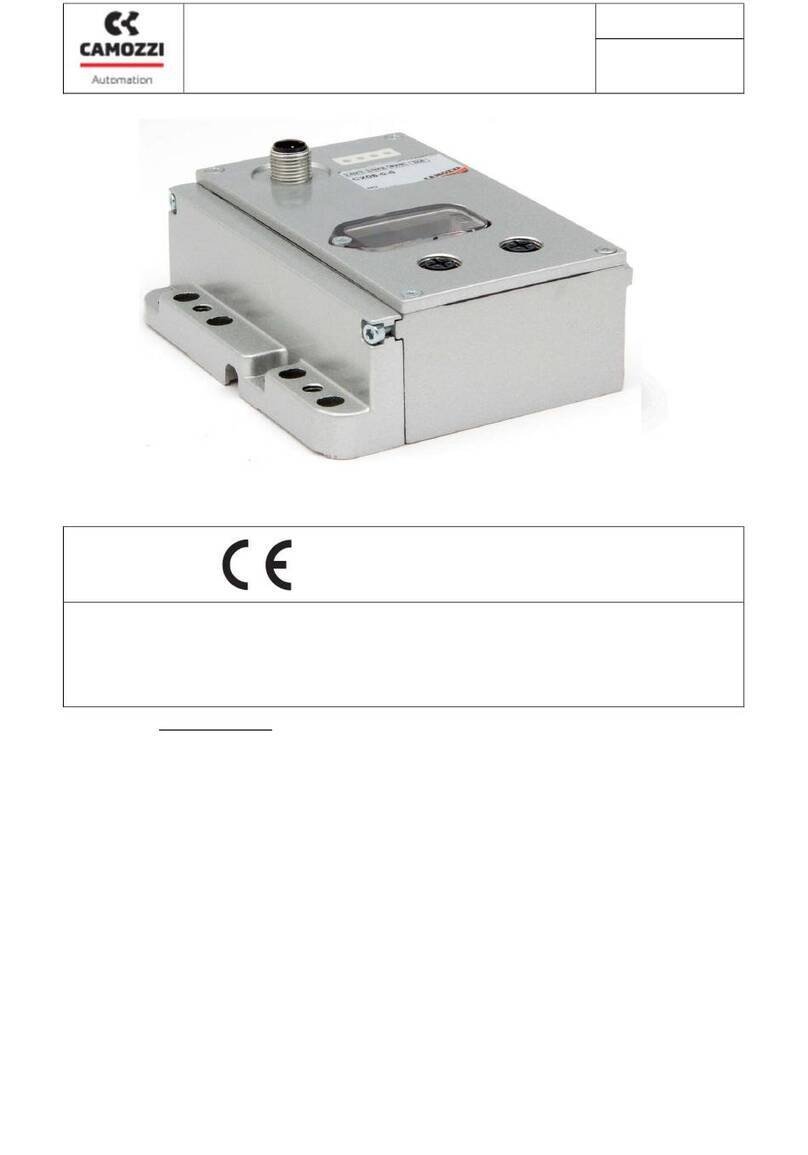
Schwank Control Touch User manual

Technical Manual
SchwankControl Touch
Schwank GmbH - Bremerhavener Straße 43 –D-50735 Cologne
Tel: +49 [0]221-7176-0 Fax: +49 [0]221-7176-288
E-mail: info@schwank.de Internet: www.schwank.de
Language: English
Date: 25. Februar 2019
Revision: V 3.0

Revision: 3.0 Page 1 of 71
Inhalt
1. General ..................................................................................................................................4
2. Safety......................................................................................................................................5
3. Technical specifications........................................................................................................6
4. Components..........................................................................................................................7
5. User interface and operation ...............................................................................................8
5.1. Idle and Home screen ...................................................................................................8
5.2. User interface..................................................................................................................9
5.2.1. Tabs...........................................................................................................................9
5.2.2. Symbols ....................................................................................................................9
5.2.3. Settings .....................................................................................................................9
5.2.4. Control unit ............................................................................................................10
5.2.5. Error screen ............................................................................................................10
5.3. Zone details...................................................................................................................11
5.3.1. Operation modes..................................................................................................11
5.3.2. Temperature and humidity setpoints...................................................................12
5.3.3. Info bar - status flags .............................................................................................13
5.4. Times menu ...................................................................................................................15
5.4.1. Time program.........................................................................................................15
5.4.2. Holiday periods......................................................................................................16
5.4.3. Date and time .......................................................................................................17
5.4.4. Time zone ...............................................................................................................17
5.4.5. Info..........................................................................................................................17
5.5. Settings ..........................................................................................................................18
5.5.1. Network settings ....................................................................................................18
5.5.2. Change PIN............................................................................................................18
5.5.3. Language ..............................................................................................................19
5.5.4. Screen ....................................................................................................................19
5.6. Special functions ..........................................................................................................19
5.6.1. Heating time extension .........................................................................................19
5.6.2. Switch-on optimisation..........................................................................................20
5.6.3. Herringbone-system fan monitoring function .....................................................20
5.6.4. Gradient limitation for setpoint value change [setpoint ramp] ........................21
6. Chimney sweep mode .......................................................................................................22

Revision: 3.0 Page 2 of 71
7. Configuration.......................................................................................................................23
7.1. Heater type configuration...........................................................................................23
7.2. Relay function configuration.......................................................................................24
7.3. Input function configuration........................................................................................25
7.4. IC4000 Modbus address assignment ..........................................................................26
7.5. Special functions [expert settings] ..............................................................................27
7.5.1. Release contact....................................................................................................27
7.5.2. Gas meter scaling .................................................................................................27
7.5.3. Duration of heating time extension .....................................................................27
7.5.4. Service interval ......................................................................................................27
7.5.5. Set temperature display .......................................................................................27
7.5.6. Modbus slave address ..........................................................................................28
7.5.7. Temperature time program OFF ..........................................................................28
7.5.8. Temperature time program ON ...........................................................................28
7.5.9. Water meter...........................................................................................................28
7.5.10. Hybrid switch-off ................................................................................................28
7.5.11. Fan error display.................................................................................................28
7.5.12. Control unit - factory settings............................................................................28
8. Parameters...........................................................................................................................29
9. Diagnostics...........................................................................................................................31
9.1. Modbus - heater...........................................................................................................31
9.2. System counters............................................................................................................33
9.3. Events ............................................................................................................................33
10. Mounting instructions.......................................................................................................35
10.1. General......................................................................................................................35
10.2. Battery........................................................................................................................35
10.3. Fuse ............................................................................................................................35
10.4. Tools............................................................................................................................35
10.5. Cable types and board wiring.................................................................................35
10.6. Bus wiring ...................................................................................................................42
10.7. Modbus wiring of the IC4000 ...................................................................................43
10.8. IC4000 error codes [DE&EN].....................................................................................46
10.9. Wiring of probes and sensors ...................................................................................47
10.9.1. RTS [room temperature sensor] & OTS [outdoor temperature sensor]..............47
10.9.2. RTS averaging ........................................................................................................49

Revision: 3.0 Page 3 of 71
10.9.3. Humidity sensor......................................................................................................50
10.9.4. Humidity sensor wiring ...........................................................................................52
10.10. Characteristic sensor curves ....................................................................................53
10.10.1. Temperature sensor...............................................................................................53
10.10.2. Humidity sensor......................................................................................................54
11. BMS engineering ..............................................................................................................55
11.1. Connection to SchwankControl control unit..........................................................55
11.2. SchwankControl configuration................................................................................55
11.3. Modbus register description [without adapter] .....................................................55
11.4. BMS connection via Modbus adapter....................................................................55
11.4.1. Wiring for converter...............................................................................................56
MODBUS RTU > MODBUS TCP or BACNet Ip ..........................................................................56
11.4.2. Wiring for converter...............................................................................................57
MODBUS RTU > KNX.................................................................................................................57
12. Appendix ..........................................................................................................................58
12.1. Drilling dimensions.....................................................................................................58
12.2. Updating firmware....................................................................................................61
12.3. Control unit factory settings .....................................................................................62
12.4. QR Code....................................................................................................................64
12.5. Remote control [webapp].......................................................................................65
13. EU Declaration of Conformity .........................................................................................66
14. SchwankControl - Product Portfolio [DE&EN] ................................................................67

Revision: 3.0 Page 4 of 71
1. General
This operating manual describes the SchwankControl heating control system, its settings and operation, as well
as connection options for sensors, automatic burner control units and building control systems.
This operating manual provides information on:
Safety
Technical specifications
Components
User interface
Mounting
Installation
Maintenance

Revision: 3.0 Page 5 of 71
2. Safety
Safety instructions
The following safety instructions make no claim to completeness. If you have any questions, uncertainties or
problems, please contact your contract partner.
Qualified personnel
Only qualified personnel may carry out work such as transport, mounting, installation, commissioning, service
and maintenance. National and company accident prevention regulations must be strictly observed.
Documentation
Before installing and commissioning, please read this documentation and any other documentation to which
reference is made in its entirety. Incorrect handling can lead to personal injury or damage to property. It is
essential that you comply with the technical data, connection details and ambient conditions.
Safety requirements
Check the electrical equipment regularly.
When working on the electrical equipment, the device must be disconnected from the power supply.
Secure the device against unintentional restarting. Switching off at the main switch does not mean
that the control is de-energised.
Setting and changing the function parameters may only be carried out by Schwank service
technicians.
Intended use
The SchwankControl control is exclusively intended for the control of hall heating systems from Schwank. Any
other use or use going beyond this is considered improper use. Schwank GmbH accepts no liability for any
resulting damage. Risk through improper use is borne solely by the user.

Revision: 3.0 Page 6 of 71
3. Technical specifications
Type
Value
Unit
Supply voltage
230 /- 5% [1~, N, PE]
V
Max. current consumption
6.3
A
Mains frequency
50 / 60
Hz
Protection class
IP 65
Ambient temperature
0...40
°C
Max. relative humidity
80
%
Mounting
Wall mounting
CE Conformity
yes
Room temperature sensor, RTS
Schwank Part No. 4065-2071
NTC 10
kΩ
Outdoor temperature sensor, OTS
Schwank Part No. 4065-2081
NTC 10
kΩ
Operation and display - touch display
4.3
480 x 272
Inch
Pixel
Dimensions [W x H x D]
260 x 190 x 170
mm
Weight
1.1
kg
Table 1: Technical specifications
Network and buses
For setting up larger heating systems, up to eight control units with a maximum of two operating units can be
connected via CAN bus. Each operating unit allows independent operation of all control units located on the
bus.
CAN 2.0B standard baud rate 125 kBit
The control unit is equipped with two RS485 interfaces for networking Schwank automatic burner control units
and for integrating the SchwankControl into building control systems.
The operating unit can also be connected to a LAN. The operating unit can be operated via a web interface
using other computers in the network.
Ethernet 10/100 Mbit

Revision: 3.0 Page 7 of 71
4. Components
The standard control integrates a control unit, an operating unit and a touch screen in a single housing.
Figure 1: Control unit
1. Type plate
2. Main switch
3. LED green: Ready for operation
4. LED yellow: Continuous light = service required
Flashing = chimney sweep mode
5. LED red: Error message
6. Touch display
Figure 2: External components

Revision: 3.0 Page 8 of 71
5. User interface and operation
The SchwankControl can only be operated via the touch screen. You can switch to individual menu items by
lightly touching the corresponding symbol.
5.1. Idle and Home screen
Logging out while the control is running activates the idle screen. Automatic logout takes place after a pre-
defined period [section 5.4.1] or by pressing the Home button. To unlock the idle screen, touch the touch
screen.
Figure 3: Idle screen
1. Home button
2. Selected control unit
3. Outside temperature
4. Date and time
5. Control unit overview
6. Switch pages
7. Direct selection of control unit
Figure 4: Home screen

Revision: 3.0 Page 9 of 71
5.2. User interface
5.2.1. Tabs
The main menu bar, which allows selection of the various tabs at all times, is located at the top of the Home
screen. As a general rule:
Tabs are identified by a symbol or text in the menu bar.
Active tabs are colour-highlighted.
5.2.2. Symbols
Home screen
User logged in
Settings [entire control unit]
Chimney sweep mode
Chimney sweep mode [active for at least one control unit]
Step-by-step navigation
Change values
OR
Close window
Disable options
Reject change
OR
Activate option
Confirm entry
Edit content
Reset values [security prompt Yes / No]
5.2.3. Settings
The SchwankControl offers two types of setting menus:
Without confirmation = The change is accepted directly. To close the menu, select the black X at the
top right.
With confirmation = Select the orange check mark to confirm the entry. To cancel / reject the
change, select the black X. The menu is closed automatically in both cases.

Revision: 3.0 Page 10 of 71
Figure 5: Control unit overview
5.2.4. Control unit
There are up to eight control units in the bus that can be controlled via one user interface. As a general rule:
all settings made are only active for the selected control unit.
Control unit identifier
Selected control unit
Control units in the bus
[greyed out = not assigned]
At least one error message in the control unit
5.2.5. Error screen
An illuminated red LED lamp on the outside of the housing signals an error message in at least one control unit.
Faulty control units are marked with an orange exclamation mark in the overview [see Figure 5]. The individual
error messages are displayed within the respective control unit.
!! At least one error
!++ Short-circuit
!-- Cable break
Ok No error
Figure 6: Error screen

Revision: 3.0 Page 11 of 71
Figure 7: Zone details
5.3. Zone details
Touch the desired control unit to open the detail view. The detail view shows the actual and setpoint
temperature in °C, the measured humidity in % and all status flags of the zone. All settings made here only
affect the selected zone.
Zone identifier
Operation mode selection [section 5.3.1]
and setting of setpoint temperatures and
humidity [section 5.3.2]
5.3.1. Operation modes
Day
Permanently adjusted to day temperature.
Night
Permanently adjusted to night temperature.
Holiday
Permanently adjusted to holiday temperature.
Antifreeze
Permanently adjusted to antifreeze temperature.
Automatic mode
Controlled according to the time programme
without taking holiday periods into account.
Automatic mode
Holiday
Controlled according to the time program with
taking holiday periods into account.
Manual mode
Available in expert mode only.
Deactivates the control for the corresponding
zone.
The output value for the heaters of the
corresponding zone can be directly specified and
adjusted.
The three-way valve in hybrid systems can also be
tested in this way.

Revision: 3.0 Page 12 of 71
Figure 8: Temperature and humidity
In addition to the operating mode, select the desired time program for the zone. This program is only used in
automatic mode.
When using automatic mode, a time program must be assigned in advance. To do this, select the "No time
program assigned" field and create a separate time program. The creation of time programs is described in
section 5.4.1.
All programmed holiday periods apply to the entire control unit, but to only those zones in automatic mode
that take holiday periods into account. Setting holiday periods is described in section 5.4.2.
5.3.2. Temperature and humidity setpoints
The setpoints for temperature and humidity
can be edited by selecting the colour-
highlighted pencil. The following screen
appears:
If the measured humidity is higher than the pre-set value, the heating request remains active, even after the
setpoint temperature has been reached, to reduce the humidity / until the setpoint value has been reached.
It is also possible to switch off the humidity control.
The manual mode setting is given in percent and refers to the output value of the control output.

Revision: 3.0 Page 13 of 71
5.3.3. Info bar - status flags
All symbols are in fixed positions and indicate the current status of the symbol [active / inactive]. Active
symbols are colour-highlighted.
1st Symbol
Switch-on optimisation [section 5.6.2]
P
Heaters are switched on earlier so that by switch-on time the setpoint
temperature has already been reached.
2nd Symbol
Current regulated temperature [section 5.3]
Day
Day activated by digital input, only in automatic mode
OR
Night
Night activated by digital input, only in automatic mode
OR
Antifreeze
OR
Holiday
OR
Manual mode
3rd Symbol
Automatic mode [section 5.3.1]
Inactive, i.e. all time programs are in the OFF state
Active, i.e. at least one of the assigned time programs is in the ON state
4th Symbol
Heating time extension [section 5.6.1]
Heating time extension is active.
5th Symbol
Humidity [section 5.3.2]
Heater request due to excessive humidity
6th Symbol
Minimum times [section 8]
-
No request due to minimum times
0
OR
Minimum pause time is active
1
OR
Minimum runtime is active

Revision: 3.0 Page 14 of 71
%
OR
Minimum full load time is active
7th Symbol
Heater status [section 8]
OFF
Heater OFF activated by digital input
OR
Partial load
OR
Full load
Heater ON activated by digital input
8th Symbol
Additional information for Symbol 7
ON
Heater is switched on
OFF
Heater is switched off
LOW
Heater running at partial load
#0...
#25
Modulation of the heater output is active
9th Symbol
Fan status
Fan is ON
10th Symbol
Event indication
Error in the zone

Revision: 3.0 Page 15 of 71
Figure 9: Times menu
Figure 10: Time programs
5.4. Times menu
You can set and edit times under the Settings menu item on the Home screen [section 5.1].
5.4.1. Time program
The ON time period is set within the time program. Outside of this period, operation changes to the OFF state.
Programming is only carried out for automatic mode and each zone must be assigned separately in the Zone
details menu item [section 5.3]. Each time program can be activated / deactivated separately.
Up to 4-day heating phases can be set within each time program.

Revision: 3.0 Page 16 of 71
Figure 12: Set day heating phases
5.4.2. Holiday periods
The holiday periods set here are taken into account in “Automatic mode including holidays” [section 5.3.1].
During this time, the selected zone is heated to the previously determined holiday temperature. A total of up
to 6 different holiday periods can be set.
Figure 13: Activate holiday periods
Figure 14: Set holiday periods
Figure11: Day heating phases overview

Revision: 3.0 Page 17 of 71
5.4.3. Date and time
Date and time are updated via LAN, if this is a possibility
5.4.4. Time zone
Automatic daylight saving yes/no
5.4.5. Info
This screen shows the serial numbers of the boards as well as the current firmware version and further LAN
information. The number in brackets behind indicates the address of the board in the CAN bus. The QR code
takes you to the instructions in the active language.
Figure 15: Date settings
Figure171: Time zone settings
Figure 18: SchwankControl Info
Figure 16: Time settings

Revision: 3.0 Page 18 of 71
5.5. Settings
The Settings menu item can be accessed via the Home screen [section 5.1].
Figure 19: General settings
5.5.1. Network settings
Figure 20: Network settings
Switch between DHCP
and static IP
5.5.2. Change PIN
Figure 21: Change PIN
SchwankControl Touch has 2 PIN
levels.
PIN 1/ Customer level: 4711
PIN 2/ Expert level
To change the PIN:
Enter old PIN Enter new PIN
Confirm new PIN

Revision: 3.0 Page 19 of 71
5.5.3. Language
Figure 22: Language selection
A wide range of languages can be
selected.
If your desired language is not
available, please contact us.
5.5.4. Screen
Figure 23: Screen settings
After the specified time has elapsed,
the user interface automatically
switches to the idle screen; the PIN
request is active.
5.6. Special functions
5.6.1. Heating time extension
Function:
The day temperature is activated for the parameterised time period.
Premise:
The overtime button for the corresponding zone must be installed.
Execution:
By pressing the overtime button for at least three seconds, the setpoint changes to day temperature for the
time period defined by the parameters, regardless of the current operating mode of the zone. As soon as this
time has elapsed, the zone automatically returns to the previous operating mode. The activated heating time
extension is displayed in the info bar [section 5.3.3].
A permanent actuation of the overtime button causes a sensor fault, which prevents further control. This results
in full load heating.
This manual suits for next models
1
Table of contents

