manuals.online logo
Brands
  1. Home
  2. •
  3. Brands
  4. •
  5. BENDIX
  6. •
  7. Control Unit
  8. •
  9. BENDIX TCS-9000 CONTROL BRAKE VALVE User manual

BENDIX TCS-9000 CONTROL BRAKE VALVE User manual

1
®
Bendix®TCS-9000™Control Brake Valve
SD-03-3674
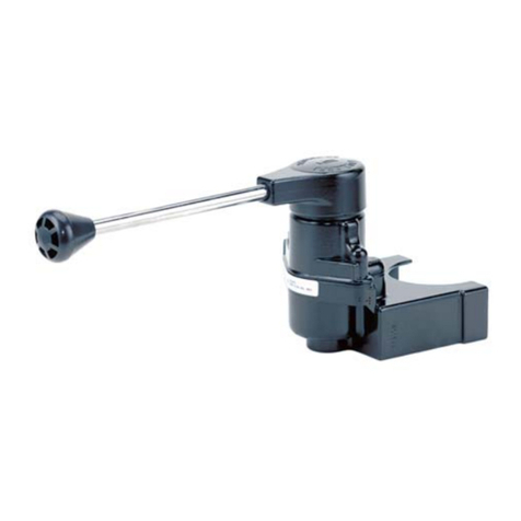
FIGURE 1 TCS-9000™trailer control valve configurations
DESCRIPTION
TheBendix®TCS-9000™controlbrakevalveisnormallyused
to operate the trailer brakes independently of the tractor
brakes.Itmaybeused,however,whereverahandcontrolled
pressuregraduation function isdesired.
TheTCS-9000™valveishandleoperatedandisdesignedfor
dash or panel mounting. It is not designed for use as a
parkingbrake control andshould never beused to holdthe
brakesapplied whentheoperator leavesthevehicle.
OPERATION
APPLYING
When the handle is pulled through its 55° arc, the cam is
rotatedaccordingly.Thecamaction forcesthecam follower
downward,compressingthegraduationspringandcreating
a force on the plunger which depresses the inlet valve and
deliversair under pressureto the deliveryport.
HOLDING
Asdeliverypressurebuildsup in the delivery port, it is also
effectiveunder theplunger causingit tobalance theforce of
the graduation spring until the inlet valve is seated against
its seat in the body and is also seated against the plunger,
thuspreventing thedelivery airfrom exhaustingthrough the
center of the plunger, maintaining the desired pressure in
thedelivery line.
RELEASING
Whenthehandleisreleasedormovedtoitsreleaseposition,
the cam follower is permitted to rise, opening the exhaust
passageand allowing theair pressure inthedelivery line to
exhaustout theexhaustport.
HANDLE
GRADUATION
SPRING
PLUNGER
INLETVALVE
EXHAUST
DELIVERY
SUPPLY
CAM
FOLLOWER
CAM
HORIZONTALPORTS
1/4" PTC
EXHAUST
FIGURE 2 TCS-9000™valve sectional
3/8" PTC
DELIVERY
3/8" PTC
SUPPLY
2
PREVENTIVE MAINTENANCE
Important: The TCS-9000™control brake valve is not
serviceable.
No two vehicles operate under identical conditions, as a
result, maintenance intervals may vary. Experience is a
valuableguideindeterminingthebestmaintenanceinterval
for air brake system components. At a minimum, the
TCS-9000™valve should be inspected every 6 months or
1500 operating hours, whichever comes first, for proper
operation.Shoulditnotmeettheelementsoftheoperational
tests noted in this document, further investigation and
replacementof thevalve may berequired.
REMOVING AND INSTALLING
Secure the vehicle with spring brakes or blocks. Drain the
reservoirwhichsuppliestheTCS-9000™valve.Removethe
fasteners which secure the mounting bracket to the panel.
Mark and disconnect the connecting air lines. Remove the
valve.
INSTALLING
A typical piping arrangement for the TCS-9000™valve is
shown in Figure 3. Check connecting air lines for integrity
and foreign material. Replace the lines if necessary.
Re-connecttheairlines. Replacefastenerssecuringbracket
topanel. Check operation of valvebycharging system and
performingtheservice check as described in this manual.
SERVICE CHECKS
OPERATING
When used as a trailer control valve connect an accurate
testgaugetothetrailerserviceline hoseandleave thetrailer
emergency or supply hose connected to the trailer or if a
traileris not available, connect the trailersupplyhose to an
unventeddummy coupling or toaplugged hose fitting. The
trailersupply valve should be inthenormal position.
Theexhaustvalvecloseswhentheoperatingleverismoved
from0° to15°and nopressureis delivered. With 15°to 40°
ofhandle travelthe valve deliversproportional intermediate
pressures up to 40psi.
In the fully applied position, up to 55° of handle travel, the
gaugeshouldregister fullreservoir pressure. Uponrelease,
thegauge should immediately register zero.
Thelocationoftheatmosphericendoftheexhaustlinefrom
the valve should be found, probably in the engine
compartment.
WiththeTCS-9000™valveinthereleaseposition,nopressure
shouldregister on the testgaugeand leakage at the endof
the exhaust line should not be greater than 100 SCCM
(1" bubble in 5 seconds).
With the valve fully applied, leakage at the exhaust line
should not be greater than 175 SCCM (1" bubble in 3
seconds).
Ifthe valve doesnot function asdescribed, or ifthe leakage
is excessive, it is recommended that it be returned to the
nearest Bendix authorized distributor for a service
replacement.
WARNING! PLEASE READ AND FOLLOW
THESE INSTRUCTIONS TO AVOID
PERSONAL INJURYOR DEATH:
When working on or around a vehicle, the following
general precautions should be observed at all times.
1. Park the vehicle on a level surface, apply the
parking brakes, and always block the wheels.
Always wear safety glasses.
2. Stop the engine and remove ignition key when
working under or around the vehicle. When
working in the engine compartment, the engine
should be shut off and the ignition key should be
removed. Where circumstances require that the
engine be in operation, EXTREME CAUTION should
be used to prevent personal injury resulting from
contact with moving, rotating, leaking, heated or
electrically charged components.
3. Do not attempt to install, remove, disassemble or
assemble a component until you have read and
thoroughly understand the recommended
procedures. Use only the proper tools and observe
all precautions pertaining to use of those tools.
4. If the work is being performed on the vehicle’s air
brake system, or any auxiliary pressurized air
systems,make certain to drain the air pressure from
all reservoirs before beginning ANY work on the
vehicle. If the vehicle is equipped with an AD-IS®
air dryer system or a dryer reservoir module, be
sure to drain the purge reservoir.
5. Following the vehicle manufacturer’s
recommended procedures, deactivate the electrical
systemin a manner that safely removes all electrical
power from the vehicle.
6. Never exceed manufacturer’s recommended
pressures.
7. Never connect or disconnect a hose or line
containing pressure; it may whip. Never remove a
componentor plugunless you are certain all system
pressure has been depleted.
3
FIGURE 3 TYPICAL SYSTEM SCHEMATIC FOR USE A TRAILER CONTROL VALVE
8. Use only genuine Bendix®replacement parts,
components and kits. Replacement hardware,
tubing,hose, fittings, etc. must be of equivalentsize,
type and strength as original equipment and be
designed specifically for such applications and
systems.
9. Components with stripped threads or damaged
parts should be replaced rather than repaired. Do
not attempt repairs requiring machining or welding
unless specifically stated and approved by the
vehicle and component manufacturer.
10. Prior to returning the vehicle to service, make
certain all components and systems are restored to
their proper operating condition.
11. For vehicles with Antilock Traction Control (ATC),
the ATC function must be disabled (ATC indicator
lamp should be ON) prior to performing any vehicle
maintenance where one or more wheels on a drive
axle are lifted off the ground and moving.
YRAMIRP ECIVRES
S
S
S
D
D
MERES
D
D
S
D
S
D
S
SD
D
MERES
xidneB
D
C
YRADNOCES ECIVRES
xidneB 9-DA
YLPPUS
SD
DB
S
D
TCS-9000™
CONTROL
VALVE
BRAKE
VALVE
MV-3™DASH
CONTROL
VALVE
MODULATOR
RELAY
VALVE
QR-1™
QUICK
RELEASE
VALVE
TP-3™
TRACTOR
PROTECTION
VALVE
QR-1C™
QUICK
RELEASE
VALVE
4BW2491 © 2005 Bendix Commercial Vehicle Systems LLC. All rights reserved. 6/2005 Printed in U.S.A.

Other BENDIX Control Unit manuals

BENDIX MV-1 MODUTROL Service manual

BENDIX

BENDIX MV-1 MODUTROL Service manual

BENDIX PP-7 TRAILER SUPPLY VALVE User manual

BENDIX

BENDIX PP-7 TRAILER SUPPLY VALVE User manual

BENDIX TABS-6 TRAILER ABS MODULE Mounting instructions

BENDIX

BENDIX TABS-6 TRAILER ABS MODULE Mounting instructions

BENDIX TC-2 TRAILER CONTROL BRAKE VALVE User manual

BENDIX

BENDIX TC-2 TRAILER CONTROL BRAKE VALVE User manual

BENDIX R-8R ELAY VALVE User manual

BENDIX

BENDIX R-8R ELAY VALVE User manual

BENDIX BP-1 BRAKE PROPORTIONING VALVES User manual

BENDIX

BENDIX BP-1 BRAKE PROPORTIONING VALVES User manual

BENDIX TW-N TWO WAY CONTROL VALVE User manual

BENDIX

BENDIX TW-N TWO WAY CONTROL VALVE User manual

BENDIX R-8P PRESSURE EQUALIZING PILOTRELAY User guide

BENDIX

BENDIX R-8P PRESSURE EQUALIZING PILOTRELAY User guide

BENDIX ATR1DC ANTILOCK TRACTION RELAY User manual

BENDIX

BENDIX ATR1DC ANTILOCK TRACTION RELAY User manual

BENDIX TR-2-TR-3-TR-4 INVERSION VALVE User manual

BENDIX

BENDIX TR-2-TR-3-TR-4 INVERSION VALVE User manual

BENDIX TW-12 User manual

BENDIX

BENDIX TW-12 User manual

BENDIX SC-3 INLINE SINGLE CHECK VALVES User manual

BENDIX

BENDIX SC-3 INLINE SINGLE CHECK VALVES User manual

BENDIX SR-4 SPRING BRAKE CONTROL VLV User manual

BENDIX

BENDIX SR-4 SPRING BRAKE CONTROL VLV User manual

BENDIX SV-1 SYNCHRO-SV-3 TRAILER RELEASE User manual

BENDIX

BENDIX SV-1 SYNCHRO-SV-3 TRAILER RELEASE User manual

BENDIX PP-3 TRAILER SUPPLY VALVE User manual

BENDIX

BENDIX PP-3 TRAILER SUPPLY VALVE User manual

BENDIX TP-3DC TRACTOR PROTECTION VALVE User manual

BENDIX

BENDIX TP-3DC TRACTOR PROTECTION VALVE User manual

BENDIX TABS-6 TRAILER ABS MODULE User manual

BENDIX

BENDIX TABS-6 TRAILER ABS MODULE User manual

BENDIX R7 VALVE 3-04 SPANISH Instruction Manual

BENDIX

BENDIX R7 VALVE 3-04 SPANISH Instruction Manual

BENDIX PP-1-2-5-8-RD-3 PUSH-PULL VALVES User manual

BENDIX

BENDIX PP-1-2-5-8-RD-3 PUSH-PULL VALVES User manual

BENDIX PP-DC PARK CONTROL VALVE User manual

BENDIX

BENDIX PP-DC PARK CONTROL VALVE User manual

BENDIX DV-2 AUTO RESERVOIR DRAIN VALVE User manual

BENDIX

BENDIX DV-2 AUTO RESERVOIR DRAIN VALVE User manual

BENDIX EVERFLOW User manual

BENDIX

BENDIX EVERFLOW User manual

BENDIX E-10PR RETARDER CTRL BRAKEVALVE User manual

BENDIX

BENDIX E-10PR RETARDER CTRL BRAKEVALVE User manual

BENDIX MV-2 CONTROL MODULE User manual

BENDIX

BENDIX MV-2 CONTROL MODULE User manual

Popular Control Unit manuals by other brands

ADLINK Technology MPC-8164 user manual

ADLINK Technology

ADLINK Technology MPC-8164 user manual

Ficosa TCU H-D MY20 manual

Ficosa

Ficosa TCU H-D MY20 manual

Videology 45S17 user manual

Videology

Videology 45S17 user manual

Emerson COMX-430 manual

Emerson

Emerson COMX-430 manual

Grafik Eye 3000 Series Installer's guide

Grafik Eye

Grafik Eye 3000 Series Installer's guide

agiliti Adapt Quick reference guide

agiliti

agiliti Adapt Quick reference guide

Grenton RGB-042-T-16 quick start guide

Grenton

Grenton RGB-042-T-16 quick start guide

Opal Kelly XEM6010 user manual

Opal Kelly

Opal Kelly XEM6010 user manual

Kemper 619 01 operating instructions

Kemper

Kemper 619 01 operating instructions

hager RTN710X manual

hager

hager RTN710X manual

National Instruments PXIe-4322 installation guide

National Instruments

National Instruments PXIe-4322 installation guide

GEM 514 Assembly instructions

GEM

GEM 514 Assembly instructions

Lowenstein Medical prismaCONNECT Instructions for use

Lowenstein Medical

Lowenstein Medical prismaCONNECT Instructions for use

Intermatic P1353ME instruction manual

Intermatic

Intermatic P1353ME instruction manual

Rohl R1041R instruction manual

Rohl

Rohl R1041R instruction manual

Bosch FLM-I 420-S Product description/Installation manual

Bosch

Bosch FLM-I 420-S Product description/Installation manual

Futura SRF05 Technical specification

Futura

Futura SRF05 Technical specification

Bosch MS 50.4 manual

Bosch

Bosch MS 50.4 manual

manuals.online logo
manuals.online logoBrands
  • About & Mission
  • Contact us
  • Privacy Policy
  • Terms and Conditions

Copyright 2025 Manuals.Online. All Rights Reserved.