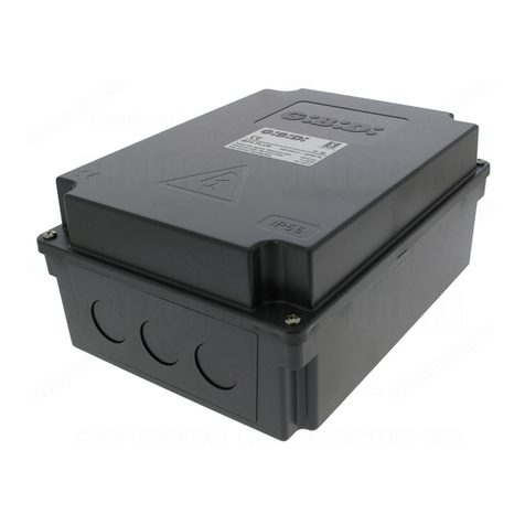
GBD BA100 Guide

I UK F E
D P NL GR
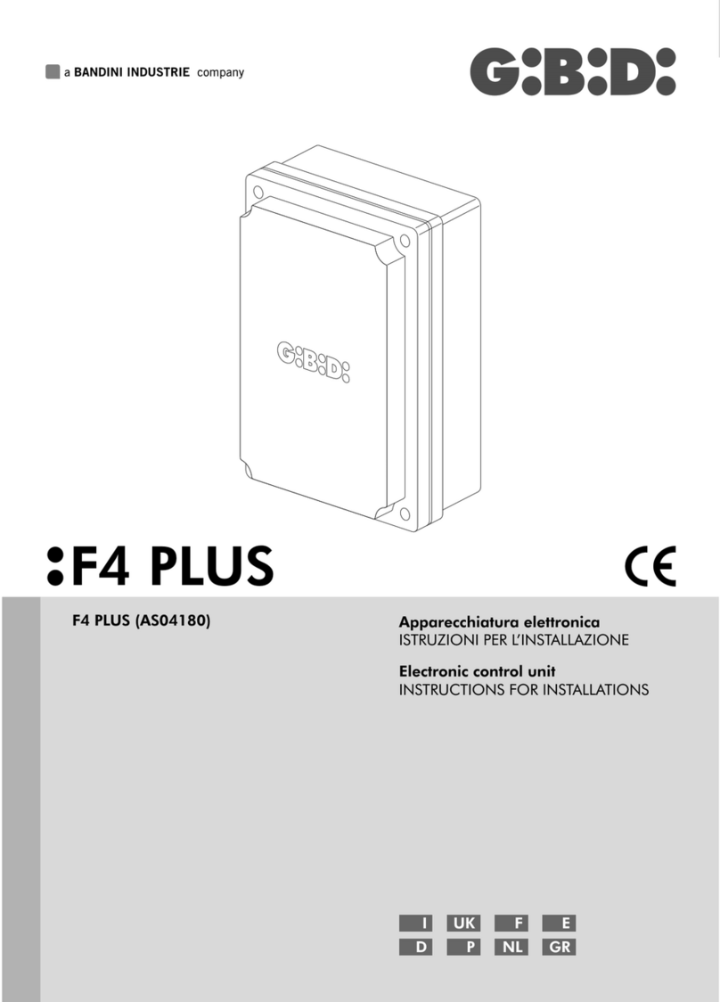
Apparecchiatura elettronica
ISTRUZIONI PER L’INSTALLAZIONE
Electronic control unit
INSTRUCTIONS FOR INSTALLATIONS
BA100 - (AS05060)
BA100

WARNINGS: This product has been tested in GI.BI.DI. verifying the perfect correspondence of the characteristics to the current directive.
GI.BI.DI. S.r.l. reserves the right to modify the technical data without prior notice depending on the product development.
AVERTISSEMENT: Ce produit a été testé chez GI.BI.DI. afin de contrôler la correspondance parfaite des caractéristiques avec les règles en vigueur.
GI.BI.DI. S.r.l. se réserve la faculté de modifier les données techniques sans aucun préavis suivant l’évolution de ses produits.
ADVERTENCIAS: Este producto ha sido ensayado en GI.BI.DI. averiguando la perfecta correspondencia de las características a las normas vigentes.
La empresa GI.BI.DI. S.r.l. se reserva el derecho de modificar los datos técnicos sin previo aviso, en función de la evolución del producto.
WARNUNGEN: Dieses Produkt wurde in GI.BI.DI. geprüft um die perfekte Entsprechung der merkmäle an die geltende vorschriften zu prüfen.
GI.BI.DI. S.r.l. behält sich das recht vor, die technischen daten der produktentwicklung entsprechend ohne voranzeige abzuändern.
WAARSCHUWINGEN: Dit product werd gekeurd in Gi.Bi.Di. Er werd nauwlettend gecontroleerd of de kenmerken van het product perfect overeenkomen met de
geldige richtlijnen.
GI.BI.DI. S.r.l. behoudt zich het recht voor de technische gegevens te wijzigen zonder waarschuwing vooraf, als dat nodig is voor de evolutie van het product.
ADVERTÊNCIA: Este produto foi testado em GI.BI.DI. verificando a correspondência perfeita das características ao normas vigentes.
A GI.BI.DI. S.r.l. reserva-se o direito de modificar os dados técnicos sem pré-aviso em função de evolução do produto.
DISPOSAL: GI.BI.DI. advises recycling the plastic components and to dispose of them at special authorised centres for electronic
components thus protecting the environment from polluting substances.
ELIMINATION : GI.BI.DI. conseille de recycler les composants en plastique et de remettre les composants électroniques à des centres
spécialisés pour éviter de polluer l'environnement avec des substances polluantes.
ELIMINACION: GI.BI.DI. aconseja reciclar los componentes de plástico y llevar los componentes electrónicos a los centros de recogida
correspondientes evitando de esta manera la contaminación ambiental con sustancias perjudiciales.
ENTSORGUNG: GI.BI.DI. empfiehlt, Kunststoffkomponenten dem Recycling zuzuführen und elektronische Komponenten in behördlich
genehmigten Zentren zu entsorgen, um die Verschmutzung der Umwelt durch Schadstoffe zu verhindern.
VERWERKING: GI.BI.DI. adviseert om de kunststof componenten te recycleren en de elektronische componenten af te voeren naar erkende
inzamelpunten, om te voorkomen dat het milieu verontreinigd wordt door vervuilende stoffen.
ELIMINAÇÃO: GI.BI.DI. Aconselha a reciclar as componentes em plástico e a eliminar as componentes electrónicas em centros habilitados
evitando desta forma poluir o ambiente com substâncias poluentes.
PLEASE READ CAREFULLY THIS MANUAL BEFORE PROCEEDING WITH THE INSTALLATION.
NOUS VOUS PRIONS DE BIEN VOULOIR LIRE ATTENTIVEMENT CE MANUEL AVANT DE PROCÉDER À L’INSTALLATION.
POR FAVOR LEER CON ATENCIÓN ESTE MANUAL ANTES DE PROCEDER CON LA INSTALACIÓN.
BITTE LESEN SIE VORSICHTIG DIESEN MANUAL BEVOR MIT DER ANGLAGE VORZUGEHEN.
LEES DEZE GEBRUIKSAANWIJZING ZEER AANDACHTIG ALVORENS DE INSTALLATIE AAN TE VATTEN.
LER COM ATENÇÃO ESTE MANUAL ANTES DE PROCEDER COM A INSTALAÇÃO.
Thank you for choosing GI.BI.DI.
Merci d’avoir choisi GI.BI.DI.
Gracias por haber elegido GI.BI.DI.
Vielen Dank, dass Sie sich für GI.BI.DI. entschieden haben.
Dank u voor uw keuze van GI.BI.DI.
Obrigado por ter escolhido a GI.BI.DI.
AVVERTENZE: Questo prodotto è stato collaudato in GI.BI.DI. verificando la perfetta corrispondenza delle caratteristiche alle direttive vigenti.
GI.BI.DI. S.r.l. si riserva la facoltà di modificare i dati tecnici senza avviso, in funzione dell’evoluzione del prodotto.
SMALTIMENTO: GI.BI.DI. consiglia di riciclare i componenti in plastica e di smaltire in appositi centri abilitati i componenti elettronici evitando
di contaminare l'ambiente con sostanze inquinanti.
LEGGERE ATTENTAMENTE QUESTO MANUALE PRIMA DI PROCEDERE ALL’INSTALLAZIONE.
Grazie per avere scelto GIBIDI.
I
UK
F
E
D
NL
P
GR
ΣΗΜΕΙΩΣΗ: Η εταιρία GI.BI.DI. έχει ελέγξει αυτό το προιόν όσον αφορά την τέλεια προσαρμογή των χαρακτηριστικών του στην ισχύουσα νομοθεσία.
Η εταιρία GI.BI.DI. S.r.l. διατηρεί το δικαίωμα αλλαγών των τεχνικών προδιαγραφών χωρίς προϋγούμενη ειδοποίηση και ανάλογα με την ανάπτυξη των
προϊόντων της.
ΔΙΑΘΕΣΗ: Η GI.BI.DI. σας συμβουλεύει να ανακυκλώσετε τα πλαστικά εξαρτήματα και να διαθέσετε τα ηλεκτρονικά εξαρτήματα μετά την
απαξίωση τους, σε εξειδικεύμενα κέντρα που υπάρχουν για τον σκοπό αυτό,συμβάλοντας έτσι στην προστασία του περιβάλλοντος απο τις
παρενέργειες της μόλυνσης.
ΠΑΡΑΚΑΛΟΥΜΕ ΝΑ ΔΙΑΒΑΣΤΕ ΠΡΟΣΕΚΤΙΚΑ ΑΥΤΕΣ ΤΙΣ ΟΔΗΓΙΕΣ ΠΡΙΝ ΤΗΝ ΕΓΚΑΤΑΣΤΑΣΗ.
Ευχαριστούμε που επιλέξατε τα προιόντα GI.BI.DI.
BA100

FIG. 1
FIG. 2
FIG. 4
FIG. 3
MOT
PHOTO 1 (NC)
START (NO)
COMMON
STOP (NC)
FCA (NC)
24Vac
230Vac 40W MAX
MOTOR 230Vac
24Vac
24Vac
230Vac 40W MAX
24Vac 3W MAX
FCC (NC)
PHOTO 2 (NC)
COMMON
21 3 4 5 6 7 8 9 10 11 12 13 14 15 16 17 18 19 20 21 22 23 24 25 26 27 28 29 30 31
U3
COMMON
BA100
Rev.0
COM
E. LOCK
E. LOCK
230Vac
230Vac
J2_
FIG. 5
BA100

I
Tipo
Alimentazione
N° motori
Alimentazione motore
Lampeggiante
Lampada spia
Alimentazione accessori
Apparecchiature
Alimentazione dispositivi di sicurezza
Ricevitore radio
Temperatura di utilizzo
Apparecchiatura elettronica per l’automazione di un
cancello a battente, porta basculante e barriera
con motore a 230Vac
220 / 230Vac monofase 50 Hz
1
220 / 230Vac
220 / 230Vac 40W max
24Vac 3W max
24Vac 8W max comprensivi di alimentazione
dispositivi di sicurezza
BA100/AS05060
24Vac 8W max comprensivi di alimentazione accessori
Ad innesto
-20°C +60°C
• Led rossi di segnalazione dei contatti n.c. (FCC, FCA, PHOTO1, STOP, PHOTO2, SAF DEV )
• Led verde di segnalazione del contatto N.A. (START).
• Pulsanti START e CLOSE a bordo scheda.
• Gestione di 1 elettroserratura 12Vac.
• Abilitazione del test delle sicurezze prima del movimento di apertura e di chiusura.
• Arresto ed inversione del moto per 2 s dopo l’intervento dei dispositivi di sicurezza. Al successivo impulso di START
il moto riparte nel senso di liberazione dell’ostacolo.
• ALIMENTAZIONE DISPOSITIVI DI SICUREZZA. Il collegamento a questa alimentazione permetterà il TEST dei
dispositivi prima del moto. A questo morsetto vanno collegati i dispositivi di sicurezza che verranno alimentati solo
durante il ciclo di funzionamento.
• Rallentamento in apertura e chiusura con finecorsa o a tempo (ultimi 5 o 10 secondi).Il rallentamento è regolabile
con opportuno TRIMMER (SLOW).
• Fotocellula 1 (PHOTO 1) attiva solo in chiusura.
• Fotocellula 2 (PHOTO 2) attiva sia in apertura che in chiusura. Il moto riprenderà sempre in apertura dopo la
liberazione della PHOTO 2.
• Regolazione forza del motore con l’opportuno TRIMMER TR4 FORCE.
• Ingresso SAF DEV con resistenza da 8K2 collegato ai dispositivi di sicurezza. In caso di non utilizzo collegare una
resistenza 8K2 tra i morsetti 26 e 29 (presente di default).
• Motore oleodinamico (DIP 5 ON): se nelle ultime 5 ore il cancello non ha effettuato manovre , viene dato un impulso
in chiusura di 10s. (mantenimento blocco oleodinamico).
DURANTE QUESTO MOVIMENTO LE SICUREZZE NON SONO ATTIVE.
CARATTERISTICHE TECNICHE / FUNZIONI
Utilizzare pressacavi adeguati ad assicurare la corretta connessione meccanica del cablaggio e tali da mantenere il
grado di protezione IP55 della scatola. (FIG. 5)
INSTALLAZIONE
BA100
2

BA100 3
I
Prima di procedere con l’installazione bisogna predisporre a monte dell’impianto un interruttore magneto
termico o differenziale con portata massima 10A. L’interruttore deve garantire una separazione omnipolare dei
contatti, con distanza di apertura di almeno 3 mm.
• Per evitare possibili interferenze, differenziare e tenere sempre separati i cavi di potenza (sezione minima
1,5mm²) dai cavi di segnale (sezione minima 0,5mm²).
• Eseguire i collegamenti facendo riferimento alle tabelle seguenti e alla serigrafia allegata. Fare molta
attenzione a collegare in serie tutti i dispositivi che vanno collegati allo stesso ingresso N.C. (normalmente
chiuso) e in parallelo tutti i dispositivi che condividono lo stesso ingresso N.A. (normalmente aperto). Una
errata installazione o un uso errato del prodotto può compromettere la sicurezza dell’impianto.
• Tutti i materiali presenti nell’imballo non devono essere lasciati alla portata dei bambini in quanto potenziali
fonti di pericolo.
• Il costruttore declina ogni responsabilità ai fini del corretto funzionamento dell'automazione nel caso non
vengano utilizzati i componenti e gli accessori di propria produzione e idonei per l'applicazione prevista.
• Al termine dell’istallazione verificare sempre con attenzione il corretto funzionamento dell’impianto e dei
dispositivi utilizzati.
• Questo manuale d’istruzioni si rivolge a persone abilitate all’installazione di “apparecchi sotto tensione”
pertanto si richiede una buona conoscenza della tecnica, esercitata come professione e nel rispetto delle
norme vigenti.
• La manutenzione deve essere eseguita da personale qualificato.
• Prima di eseguire qualsiasi operazione di pulizia o di manutenzione , scollegare l’apparecchiatura dalle rete di
alimentazione elettrica.
• L’apparecchiatura qui descritta deve essere utilizzata solo all’uso per il quale è stata concepita.
• Verificare lo scopo dell'utilizzo finale e assicurarsi di prendere tutte le sicurezze necessarie
• L’ utilizzo dei prodotti e la loro destinazione ad usi diversi da quelli previsti, non è stata sperimentata dal
costruttore, pertanto i lavori eseguiti sono sotto la completa responsabilità dell’installatore.
• Segnalare l’automazione con targhe di avvertenza che devono essere visibili.
• Avvisare l’utente che bambini o animali non devono giocare o sostare nei pressi del cancello.
• Proteggere adeguatamente i punti di pericolo (per esempio mediante l’uso di una costa sensibile).
In caso di guasto o anomalie di funzionamento staccare l’alimentazione a monte dell’apparecchiatura e
Chiamare l’assistenza tecnica.
Verificare periodicamente il funzionamento delle sicurezze. Le eventuali riparazioni devono essere eseguite da
personale specializzato usando materiali originali e certificati.
Il prodotto non deve essere usato da bambini o persone con ridotte capacità fisiche, sensoriali o mentali, oppure
mancanti di esperienza e conoscenza, a meno che non siano stati correttamente istruiti.
Non accedere alla scheda per regolazioni e/o manutenzioni.
ATTENZIONE: IMPORTANTI ISTRUZIONI DI SICUREZZA.
E' importante per la sicurezza delle persone seguire queste istruzioni.
Conservare il presente libretto di istruzioni
AVVERTENZE PER L’INSTALLAZIONE
AVVERTENZE PER L’UTENTE

BA100
4
I
Descrizione
Collegamento primario trasformatore 230 Vac (cavi neri)
Collegamento secondario trasformatore 14 Vac (cavi rossi)
Collegamento secondario trasformatore 22 Vac (cavi blu)
Faston
Posizione
Morsetto
1
F1
M2
2
F2
3
F3
Posizione
Valore
Posizione
Tipo
Segnale
M1_8 M1_11
2A
1
RAPIDO
NEUTR
M1_9 M1_10
500 mA
2
RAPIDO
PHASE
M1_12 M1_13
3,15A
3
4
RAPIDO
EARTH
EARTH
Descrizione
Descrizione
Protezione secondario trasformatore
Alimentazione 230 Vac
Protezione accessori
Alimentazione 230 Vac
Protezione primario trasformatore e motore
Collegamento filo di terra
Collegamento filo di terra
COLLEGAMENTI ELETTRICI: FASTON
FUSIBILI DI PROTEZIONE
COLLEGAMENTI ELETTRICI: MORSETTIERE
Collegamento motore (apertura)
Comune motore
Collegamento motore (chiusura)
Uscita luce di cortesia 230Vac 40W
Uscita luce di cortesia 230Vac 40W
Uscita lampeggiatore 230Vac 40W
Uscita lampeggiatore 230Vac 40W
M1
5OPEN MOTOR
6COM MOTOR
7
8
9
10
11
CLOSE MOTOR
LIGHT 230V
LIGHT 230V
LAMP 230V
LAMP 230V
Si accende contemporaneamente al
motore e si spegne 180s dopo la fine
del movimento.
Lampeggio lento in apertura, spento in
pausa, lampeggio veloce in chiusura.
Lampeggio lento in apertura,
accesa fissa in pausa, lampeggio
veloce in chiusura.
Attenzione: se vengono utilizzati i fine
corsa per fermare il moto del cancello
bisogna escludere il colpo d’ariete.
Vedi dip n.3 SW1
Alimentazione 24Vac accessori esterni (fotocellule, radio, etc)
Ingresso START (N.A.)
Alimentazione 24Vac accessori esterni (fotocellule, radio, etc)
Ingresso finecorsa chiude (N.C)
Positivo elettroserratura
Ingresso finecorsa apre (N.C.)
Negativo elettrosettatura
Ingresso FOTOCELLULA 1 (N.C.)
Alimentazione positiva sicurezze con test (vedi dip n.4 SW1) il negativo
va collegato al morsetto 18
Ingresso STOP (N.C.)
Uscita lampeggiatore 230Vac 40W
COMUNE INGRESSI - USCITE
Uscita lampeggiatore 230Vac 40W
M3
M4
12
19
24Vac
START
13
20
24Vac
FCC
14
21
15
22
16
23
17
24
18
E.LOCK 12V
FCA
E.LOCK 12V
PHOTO 1
+SAFETY
STOP
SPIA 24Vac
COM
SPIA 24Vac

SENZA BORDO
SENSIBILE
8K2
26
29
BORDO SENSIBILE
CON RESISTENZA 8K2
INTEGRATA
26
29
BORDO SENSIBILE
CON CONTATTO N.C.
26
29
8K2
BA100 5
I
M5
25
27
28
29
26
PHOTO 2
ENCODER
COM
COM
SAF. DEV
Ingresso FOTOCELLULA 2 (N.C.)
Non implementato
COMUNE INGRESSI – USCITE
COMUNE INGRESSI – USCITE
Ingresso DISPOSITIVI DI SICUREZZA.
• In caso di non utilizzo lasciare la resistenza 8K2 inserita tra i morsetti
26 e 29 (Fig.2) .
• Se si utilizza un dispositivo di sicurezza già predisposto con resistenza 8K2
da collegare tra i morsetti 26 e 29 (Fig.3) togliere la resistenza già inserita
• se si utilizza un dispositivo di sicurezza con contatto N.C. collegare in
serie al contatto la resistenza 8K2 in dotazione (Fig.4).
•
•
M6
30 GND
31 ANT
Ingresso CALZA ANTENNA
J2_RX
Connettore per ricevente ad innesto
Ingresso SEGNALE ANTENNA
DIP
DIP 1
DIP 2
DIP 1
DIP 2
DIP 1
DIP 2
STATO FUNZIONE
OFF
OFF
OFF
ON
ON
OFF
PASSO - PASSO CON STOP
CONDOMINALE
PASSO - PASSO
DESCRIZIONE
PROGRAMMAZIONE FUNZIONI (DIP SWITCH SW1)
FIG. 2
FIG. 4
FIG. 3
I impulso di Start
II impulso di Start
III impulso di Start
APRE
CHIUDE
APRE
I impulso di Start
II impulso di Start
III impulso di Start
IV impulso di Start
APRE
ARRESTA (non richiuderà in automatico)
CHIUDE
APRE
In apertura non riceve altri comandi di Start dopo il primo, in pausa
successivi comandi di Start ricaricano il tempo di pausa
I impulso di Start
Successivi impulsi di Start
Pausa da FCA o tempo di apertura
Impulso di Start durante la pausa
Successivo impulso di Start
APRE Ininfluenti
Ricarica il tempo pausa (se dip 6 ON)
oppure CHIUDE (se dip 6 OFF)
DIP 1
DIP 2
ON
ON UOMO PRESENTE
Pulsanti a bordo scheda:
Se mantenuto premuto il pulsante Start
Se mantenuto premuto il pulsante Close
Da morsettiera:
Chiudendo il contatto Start
Chiudendo il contatto PHOTO 1 e ponendo il DIP n.1 del SW 2 in OFF chiude
APRE
APRE
APRE
CHIUDE

BA100
6
I
DIP 3
COLPO D’ARIETE
E PRELAMPEGGIO
Abilita il prelampeggio in apertura e in chiusura per 3 secondi prima del
movimento della porta.
Al termine del prelampeggio viene dato un impulso in chiusura di 1 s
(colpo d’ariete) per favorire lo sgancio dell’elettroserratura (solo in apertura).
ON
OFF
Disabilita la funzione colpo d’ariete e prelampeggio.
DIP 4
TEST SICUREZZE
Abilita il TEST dei dispositivi di sicurezza prima di attivare il ciclo di apertura
e chiusura. Solo se i dispositivi saranno perfettamente funzionanti il ciclo potrà
iniziare, in caso contrario tre lampeggi prolungati indicheranno l’anomalia.
NB: Dopo la fase di avviamento portare SW5 in posizione 2-3
ON
OFF
Disabilita il test dei dispositivi di sicurezza.
DIP 5
MOTORE OLEODINAMICO
ON
OFF
L’operatore è di tipo oleodinamico.
L’operatore è di tipo elettromeccanico. NOTA1*
DIP 6
RICHIUSURA AUTOMATICA
ON
OFF
Abilita la chiusura automatica dopo il tempo di pausa regolabile
tramite il trimmer TR3 PAUSE da 2 a 200 s.
Disabilita la chiusura automatica.
NO RALLENTAMENTO Funzione rallentamento disabilitata.
RALLENTAMENTO
CON FINECORSA
Abilita il rallentamento sia in apertura che in chiusura quando viene intercettato
il rispettivo fine corsa. Se i jumper JP1 JP2 sono chiusi i tempi di rallentamento
sono regolabili da 1 a 33 secondi, se i jumper sono aperti i tempi sono regolabili
da 1 a 16 secondi. La regolazione avviene tramite i trimmers OPEN TR5 e
CLOSE TR2. NB. CON QUESTA FUNZIONE I FINE CORSA DETERMINANO
L’INIZIO DEL RALLENTAMENTO
RALLENTAMENTO
5 SECONDI
Abilita il rallentamento sia in apertura che in chiusura 5 secondi prima della fine
del tempo di lavoro. In questo caso fare attenzione alla regolazione dei tempi
di lavoro TR2 / TR5
RALLENTAMENTO
10 SECONDI
DIP 7
DIP 9
OFF
OFF
DIP 7
DIP 9
OFF
ON
DIP 7
DIP 9
ON
OFF
DIP 7
DIP 9
ON
ON
Abilita il rallentamento sia in apertura che in chiusura 10 secondi prima della fine
del tempo di lavoro. In questo caso fare attenzione alla regolazione dei tempi
di lavoro TR2 / TR5
DIP 8
RICHIUSURA RAPIDA
PHOTO 1
ON
OFF
Riduce il tempo di pausa a 1,5 s dopo l’intervento delle fotocellule.
Disabilita la funzione di richiusura rapida
DIP 10
NO STOP
ON
OFF
Disabilita il comando STOP
Abilita il comando STOP
IMPOSTAZIONI DI DEFAULT (DIP SWITCH SW1)
DIP 1 E DIP 2 entrambi OFF: Passo passo con stop
DIP 3 OFF: Colpo d’ariete e prelampeggio disattivati
DIP 4 OFF: Test dispositivi di sicurezza escluso
DIP 5 OFF: Motore elettromeccanico
DIP 6 ON: Chiusura automatica abilitata
DIP 7 E 9 ENTRAMBI OFF: Rallentamenti esclusi
DIP 8 OFF: Richiusura rapida esclusa
DIP 10 OFF: STOP Abilitato
NOTA 1 *
In caso di inversione di marcia, da apertura a chiusura e viceversa, i tempi di apertura e chiusura saranno uguali in caso di configurazione
elettromeccanica mentre saranno differenti in caso di configurazione oleodinamica per tenere conto della differente velocità dell’operatore nelle 2
fasi. In alcune applicazioni oleodinamiche con operatori che hanno la stessa velocità sia in apertura che in chiusura (ad. es. FLOOR 810), è
consigliabile abilitare la configurazione elettromeccanica.

BA100 7
I
Le impostazioni vengono memorizzate durante la fase di riposo (cancello chiuso).
DIP
FUNZIONE
STATO
DIP 1
ON
OFF
DIP 2
ON
OFF
DIP 3
ON
OFF
DIP 4
ON
OFF
ESCLUSIONE PHOTO 1
ABILITAZIONE PHOTO 1
ESCLUSIONE PHOTO 2
ABILITAZIONE FINECORSA APERTURA
ESCLUSIONE FINECORSA APERTURA
ABILITAZIONE FINECORSA CHIUSURA
ESCLUSIONE FINECORSA CHIUSURA
ABILITAZIONE PHOTO 2
IMPOSTAZIONI DI DEFAULT (DIP SWITCH SW2)
DIP 1 ON: Esclude PHOTO 1
DIP 2 ON: Esclude PHOTO 2
DIP 3 ON: Esclude FINECORSA CHIUSURA
DIP 4 ON: Esclude FINECORSA APERTURA
REGOLAZIONE TRIMMER
I trimmer TR1, e TR4 possono essere regolati anche durante il movimento del cancello, verificando così
immediatamente l'effetto. I trimmer TR2, TR3 e TR5 vengono memorizzati solo durante la fase di riposo
(cancello chiuso).
Trimmer Funzione Descrizione
TR1 SLOW Regola il livello del RALLENTAMENTO. Ruotando il trimmer in senso orario si ha una maggiore velocità/forza del
cancello). NB: Con motore elettromeccanico (DIP 5 OFF) il trimmer è ininfluente e il rallentamento sarà fisso.
TR2 CLOSE Regola il TEMPO di CHIUSURA da 2 a 100 s, se JP2 è aperto. Il valore aumenta ruotando in senso orario il trimmer.
Regola il TEMPO di CHIUSURA da 2 a 200 s, se JP2 è chiuso. Il valore aumenta ruotando in senso orario il trimmer.
TR3 Regola il TEMPO di PAUSA da 2 a 200 s. Il valore aumenta ruotando in senso orario il trimmer.
PAUSE
TR4 FORCE Regola il livello della FORZA motore. La forza aumenta ruotando in senso orario il trimmer.
NB. IN CASO DI OPERATORI OLEODINAMICI LA FORZA DEVE ESSERE AL MASSIMO
TR5 OPEN Regola il TEMPO di APERTURA da 2 a 100 s. se JP1 è aperto. Il valore aumenta ruotando in senso orario il trimmer.
Regola il TEMPO di APERTURA da 2 a 200 s. se JP1 è chiuso. Il valore aumenta ruotando in senso orario il trimmer.
IMPOSTAZIONI DI DEFAULT
TRIMMER TR1, TR2, TR3, TR4 e TR5 sono regolati a metà della loro corsa.
PROGRAMMAZIONE FUNZIONI (DIP SWITCH SW2)

Gi.Bi.Di consiglia di riciclare i componenti in plastica e di smaltire in appositi centri abilitati i
componenti elettronici evitando perciò di contaminare l’ambiente con sostanze inquinanti.
BA100
8
I
1 Verificare i collegamenti elettrici: un collegamento errato può risultare dannoso sia per l’apparecchiatura che
per l’operatore.
2 Verificare l’impostazione corretta dei dip, secondo le esigenze.
3 Verificare che i led rossi dei contatti normalmente chiusi siano accesi, ed il led verde del contatto
normalmente aperto sia spento.
4 Verificare che facendo intervenire i fine corsa utilizzati si spengano i led corrispondenti.
5 Verificare che passando attraverso il raggio delle fotocellule i led corrispondenti si spengano.
6 Verificare che facendo intervenire i dispositivi di sicurezza i led corrispondenti si spengano.
7 Portare l’anta in posizione di metà corsa e bloccare il motore. Rimuovere eventuali ostacoli nel raggio
d’azione del cancello quindi dare un comando di START. Al primo comando di START comincia una fase di
apertura, quindi verificare che la direzione del moto del cancello sia corretta. In caso contrario invertire i fili
nei morsetti MOTOR OPEN (5) – MOTOR CLOSE (7).
8 Regolare il trimmer TR3 (PAUSE) impostando quindi il tempo di pausa desiderato (al max in senso orario si
ottengono 200 s).
9 Regolare il trimmer TR2 (CLOSE) impostando quindi il tempo di chiusura desiderato.
10 Regolare il trimmer TR5 (OPEN) impostando quindi il tempo di apertura desiderato.
11 Durante il moto ruotare il trimmer TR4 (FORCE) fino a trovare il valore di forza/velocità desiderato.
12 Durante il moto rallentato ruotare il trimmer TR1 (SLOW) fino a trovare il valore di forza/velocità desiderato
VERIFICHE FINALI E COLLAUDO
Ricordarsi di posizionare il ponticello SW5 nella posizione 2-3 prima di attivare il normale
funzionamento, altrimenti con l’uso del TEST SICUREZZE verrà segnalata un’ anomalia
e il cancello resterà bloccato.
SMALTIMENTO BA100

BA100 9
I
Dichiarazione di conformità CE
Il fabbricante:
GI.BI.DI.
Via Abetone Brennero, 177/B,
46025 Poggio Rusco (MN) ITALY
Dichiara che i prodotti:
APPARECCHIATURA ELETTRONICA BA100
Sono conformi alle seguenti Direttive CEE:
•
e che sono state applicate le seguenti norme armonizzate:
•
•
Data 08/01/15
S.r.l.
Direttiva LVD 2006/95/CE e successive modifiche;
• Direttiva EMC 2004/108/CE e successive modifiche;
EN60335-1,
EN61000-6-2, EN61000-6-3
Il Rappresentante Legale
Michele Prandi

Use glands adequate to ensure proper mechanical connection of cable and maintain the box protection degree IP55.
(FIG. 5)
INSTALLATION
BA100
10
UK
Type
Power supply
No. of motors
Motor power supply
Flashlight
Warning light
Accessory power supply
Control unit
Safety device power supply
Plug-in
Operating temperature
Electronic control unit for automation of a swing gate,
overhead door and barrier with 230 VAC motor
220 / 230 VAC, single-phase, 50 Hz
1
220 / 230 VAC
220 / 230 VAC 40W max
24 VAC 3W max
24 VAC 8W max including safety device power supply
BA100/AS05060
24 VAC 8W max including accessory power supply
radio receiver
-20°C +60°C
• Red warning LEDs of N.C. contacts (CLOSING LIMIT SWITCH, OPENING LIMIT SWITCH, STOP,
PHOTOCELL 2, SAFETY DEVICE)
• Green warning LED of N.O. contact (START)
• START and CLOSE buttons on the board.
• Control of one 12 VAC electric lock.
• Safety switch test activation before the opening and closing movements.
• Stop and motion inversion for 2 seconds after intervention of the safety devices. At the next START pulse the
motion restarts in the obstacle freeing direction.
• SAFETY DEVICE POWER SUPPLY Connection to this power supply allows TESTING the devices before
motion. The safety devices must be connected to this terminal and will be powered only during the operating
cycle.
• Deceleration during opening and closing with limit switch or timed (last 5 or 10 seconds). Deceleration is
adjustable with the relative TRIMMER (SLOW)
• Photocell 1 (PHOTO 1) activates during closing only.
• Photocell 2 (PHOTO 2) activates both during opening and closing. The motion will always resume in opening
after PHOTO 2 is freed.
• Motor force adjustment with the TRIMMER TR4 FORCE.
• Input SAF DEV with 8K2 resistor connected to the safety devices. If not used connect an 8K2 resistor between
terminals 26 and 29 (present as default).
• Hydraulic motor (DIP 5 ON): if the gate has not performed any manoeuvres in the last 5 hours, a 10-second
closing pulse is given. (hydraulic lock retention)
DURING THIS MOVEMENT THE SAFETY DEVICES ARE NOT ACTIVE.
TECHNICAL SPECIFICATIONS / FUNCTIONS

BA100 11
UK
Before proceeding with installation, fit a magnetothermal or differential switch with a maximum capacity of 10A
upstream of the system. The switch must guarantee omnipolar separation of the contacts with an opening
distance of at least 3 mm.
• To prevent possible interference, differentiate and always keep the power cables (minimum cross-section 1.5
mm²) separate from the signal cables (minimum cross-section 0.5 mm²).
• Make the connections referring to the following tables and to the attached screen-print. Be extremely careful to
connect in series all the devices that are connected to the same N.C. (normally closed) input, and in parallel all
the devices that share the same N.O. (normally open) input. Incorrect installation or improper use of the
product may compromise system safety.
• Keep all the materials contained in the packaging away from children, since they pose a potential risk.
• The manufacturer declines all responsibility for improper functioning of the automated device if the original
components and accessories suitable for the specific application are not used.
• After installation, always carefully check proper functioning of the system and the devices used.
• This instruction manual addresses persons qualified for installation of "live equipment". Therefore, good
technical knowledge and professional practice in compliance with the regulations in force are required.
• Maintenance must be carried out by qualified personnel.
• Before carrying out any cleaning or maintenance operation, disconnect the control unit from the mains.
• This control unit may only be used for the purpose for which it was designed.
• Check the aim of the final use and make sure that all safety measures are taken.
• Use of the product for purposes different from the intended use has not been tested by the manufacturer,
therefore any work is carried out on full responsibility of the installer.
• Mark the automated device with visible warning plates.
• Warn the user that children or animals may not play or stand around near the door.
• Appropriately protect the danger points (for example, using a sensitive frame).
In the event of an operating fault or failure, cut the power upstream of the control unit and call Technical Service.
Periodically check functioning of the safety devices. Any repairs must be carried out by specialised personnel
using original and certified materials.
The appliance is not to be used by children or people with reduced physical, sensory or mental capabilities, or
lack of experience and knowledge, unless they have been given supervision or instruction.
Do not touch the card for adjustments and/or maintenance.
WARNING: IMPORTANT SAFETY INSTRUCTIONS.
It is very important to follow the present instructions for your own safety.
Please keep this manual.
INSTALLATION WARNINGS
WARNINGS FOR THE USER

BA100
12
UK
Description
Primary connection of 230 VAC transformer (black cables)
Secondary connection of 14 VAC transformer (red cables)
Secondary connection of 22 VAC transformer (blue cables)
Faston
Position
Terminal
1
F1
M2
2
F2
3
F3
Position
Value
Position
Type
Signal
M1_8 M1_11
2A
1
FAST
NEUTR
M1_9 M1_10
500 mA
2
FAST
PHASE
M1_12 M1_13
3,15A
3
4
FAST
EARTH
EARTH
Description
Description
Secondary transformer protection
230 VAC power supply
Accessory protection
230 VAC power supply
Transformer and motor primary protection
Ground wire connection
Ground wire connection
ELECTRICAL CONNECTIONS: FASTONS
PROTECTION FUSES: FASTONS
ELECTRICAL CONNECTIONS: TERMINAL BOARD
Motor connection (opening)
Motor common
Motor connection (closing)
Courtesy light output 230V 40W
Courtesy light output 230V 40W
Flashlight output 230 VAC 40W
Flashlight output 230 VAC 40W
M1
5OPEN MOTOR
6COM MOTOR
7
8
9
10
11
CLOSE MOTOR
LIGHT 230V
LIGHT 230V
LAMP 230V
LAMP 230V
Comes on together with the motor and
goes off 180s after the end of the
movement.
Slow flashing during opening, off during
pause, fast flashing during closing.
Slow flashing during opening, on fixed
during pause, fast flashing during
closing.
Warning: If the limit switches are used
to stop the gate motion, the water ham-
mer must be disabled. See DIP3 SW1
24 VAC external accessory power supply (photocells, radio, etc.)
START input (N.O.)
24 VAC external accessory power supply (photocells, radio, etc.)
Closing limit switch input (N.C.)
Positive electric lock
Opening limit switch input (N.C.)
Negative electric lock
PHOTOCELL 1 input (N.C.)
Safety device positive power supply with test (see DIP4 SW1), the negative
must be connected to terminal 18
STOP input (N.C.)
24 VAC warning light output
COMMON INPUTS/OUTPUTS
24 VAC warning light output
M3
M4
12
19
24Vac
START
13
20
24Vac
FCC
14
21
15
22
16
23
17
24
18
E.LOCK 12V
FCA
E.LOCK 12V
PHOTO 1
+SAFETY
STOP
SPIA 24Vac
COM
SPIA 24Vac

BA100 13
UK
WITHOUT
CONDUCTIVE EDGE
8K2
26
29
CONDUCTIVE EDGE
WITH RESISTANCE
8K2 INTEGRATED
26
29
CONDUCTIVE EDGE
WITH N.C. CONTACT
26
29
8K2
M5
25
27
28
29
26
PHOTO 2
ENCODER
COM
COM
SAF. DEV
PHOTOCELL 2 input (N.C.)
Non implementato
COMMON INPUTS/OUTPUTS
COMMON INPUTS/OUTPUTS
SAFETY DEVICE input
•If not used leave the 8K2 resistor in place between terminals 26 and 29 (Fig.2).
•If using a safety device already with 8K2 resistor connected between
terminals 26 and 29 (Fig.3) remove the resistor fitted.
•If using a safety device with N.C. contact, connect the 8K2 resistor provided
in series to the contact (Fig.4).
M6
30 GND
31 ANT
ANTENNA GROUND input
J2_RX
Connector for plug-in receiver
ANTENNA SIGNAL input
DIP
DIP 1
DIP 2
DIP 1
DIP 2
DIP 1
DIP 2
DIP 1
DIP 2
STATUS FUNCTION
OFF
OFF
ON
ON
OFF
ON
ON
OFF
STEP-BY-STEP WITH STOP
DEAD MAN
CONDOMINIUM
STEP-BY-STEP
DESCRIPTION
FUNCTION PROGRAMMING (DIP SWITCH SW1)
FIG. 2
FIG. 4
FIG. 3
I Start pulse
II Start pulse
III Start pulse
IV Start pulse
Buttons on the board:
If Start button is held down
If Close button is held down
From terminal board:
Closing the Start contact
Closing the PHOTO 1 contact and setting DIP1 of SW2 to OFF the door closes
OPEN
STOP (will not reclose automatically)
CLOSE
OPEN
I Start pulse
II Start pulse
III Start pulse
OPEN
CLOSE
OPEN
During opening it does not receive other Start commands after the first
one; during Pause subsequent Start commands reload the pause time
I Start pulse
Subsequent Start pulses
Pause from opening limit switch or opening time
Start pulse during pause
Subsequent Start pulse
OPEN Uninfluential
Reloads the pause time (if DIP 6 ON)
or CLOSES (if DIP 6 OFF)
OPEN
OPEN
CLOSE
OPEN

BA100
14
UK
DIP 3
WATER HAMMER
AND PRE-FLASHING
Enables pre-flashing during opening and closing for 3 seconds before moving
the door. After pre-flashing a 1-second closing pulse is given (water hammer)
to aid release of the electric lock (during opening only).
ON
OFF
Disables the water hammer and pre-flashing function
DIP 4
SAFETY DEVICE TEST
Enables the safety device TEST before activating the opening and closing cycle.
The cycle can only start if the devices work perfectly, if not, three prolonged
flashes indicate the fault.
NB: After the start phase, set SW5 to position 2-3
ON
OFF
Disables the safety device test.
DIP 5
HYDRAULIC MOTOR
ON
OFF
The operator is hydraulic
The operator is type electromechanical NOTE1*
DIP 6
AUTOMATIC CLOSING
ON
OFF
Enables automatic closing after the pause time adjustable with the trimmer TR3
PAUSE between 2 and 200 seconds.
Disables automatic closing.
NO DECELERATION Deceleration function disabled
DECELERATION WITH
LIMIT SWITCH
Enables deceleration during both opening and closing when the respective limit switch is
intercepted. If the jumpers JP1 and JP2 are closed, the deceleration time can be
adjusted from 1 to 33 seconds; if the jumpers are open, the times can be adjusted from
1 to 16 seconds. The adjustment is made with the trimmers OPEN TR5 and CLOSE
TR2. NB. WITH THIS FUNCTION THE LIMIT SWITCHES DETERMINE
DECELERATION START
5-SECOND
DECELERATION
Enables deceleration during both opening and closing 5 seconds before the end
of the run time. In this case, pay attention to adjustment of the TR2 / TR5 run
times.
10-SECOND
DECELERATION
Enables deceleration during both opening and closing 10 seconds before the end of the
run time. In this case, pay attention to adjustment of the TR2 / TR5 run times.
DIP 8
FAST CLOSING PHOTO 1
ON
OFF
Reduces the pause time to 1.5 seconds after intervention of the photocells.
Disables the fast closing function.
DIP 10
NO STOP
ON
OFF
Disables the STOP command
Enables the STOP command
DEFAULT SETTINGS (DIP SWITCH SW1)
DIP 1 and DIP 2 both OFF: Step-by-step with stop
DIP 3 OFF: Water hammer and pre-flashing deactivated
DIP 4 OFF: Safety device test disabled
DIP 5 OFF: Electromechanical motor
DIP 6 ON: Automatic closing enabled
DIP 7 AND DIP 9 BOTH OFF Deceleration disabled
DIP 8 OFF: Fast closing disabled
DIP 10 OFF: STOP enabled
NOTE 1 *
If motion is inverted from opening to closing and vice versa, the opening and closing times will be the same in the case of an electromechanical
configuration, but different in the case of a hydraulic configuration in order to take into account the different speed at which the operator runs in
the two phases. In some hydraulic applications where the operators run at the same speed during opening and closing (e.g. FLOOR 810), it is
advisable to enable electromechanical configuration.
DIP 7
DIP 9
OFF
OFF
DIP 7
DIP 9
OFF
ON
DIP 7
DIP 9
ON
OFF
DIP 7
DIP 9
ON
ON

BA100 15
UK
The settings are stored during the rest phase (door closed).
DIP
FUNCTION
STATUS
DIP 1
ON
OFF
DIP 2
ON
OFF
DIP 3
ON
OFF
DIP 4
ON
OFF
PHOTO 1 DISABLED
PHOTO 1 ENABLED
PHOTO 2 DISABLED
OPENING LIMIT SWITCH ENABLED
OPENING LIMIT SWITCH DISABLED
CLOSING LIMIT SWITCH ENABLED
CLOSING LIMIT SWITCH DISABLED
PHOTO 2 ENABLED
DEFAULT SETTINGS (DIP SWITCH SW2)
DIP 1 ON: PHOTO 1 DISABLED
DIP 2 ON: PHOTO 2 DISABLED
DIP 3 ON: CLOSING LIMIT SWITCH DISABLED
DIP 4 ON: OPENING LIMIT SWITCH DISABLEDSA APERTURA
TRIMMER ADJUSTEMENT
The trimmers TR1, and TR4 can be adjusted also during gate movement and thus the effect immediately
checked. The trimmers TR2, TR3 and TR5 are stored only during the rest phase (gate closed).
Trimmers Function Description
TR1 SLOW Adjusts the DECELERATION level. Turning the trimmer clockwise the gate speed/force is increased)
NB. With an electromechanical motor (DIP 5 OFF) the trimmer is uninfluential and deceleration will be fixed.
TR2 CLOSE Adjusts the CLOSING TIME from 2 to 100 seconds if JP2 is open. The value is increased by turning the trimmer clockwise.
Adjusts the CLOSING TIME from 2 to 200 seconds if JP2 is closed. The value is increased by turning the trimmer clockwise.
TR3 Adjusts the PAUSE TIME from 2 to 200 seconds. The value is increased by turning the trimmer clockwise.
PAUSE
TR4 FORCE Adjusts the motor FORCE level. The force is increased by turning the trimmer clockwise.
NB. IN CASE OF HYDRAULIC OPERATORS THE FORCE MUST BE AT MAXIMUM
TR5 OPEN Adjusts the OPENING TIME from 2 to 100 seconds if JP1 is open. The value is increased by turning the trimmer clockwise.
Adjusts the OPENING TIME from 2 to 200 seconds if JP1 is closed. The value is increased by turning the trimmer clockwise.
DEFAULT SETTINGS
TRIMMERS TR1, TR2, TR3, TR4, TR5 are adjusted to halfway their travel.
FINCTION PROGRAMMING (DIP SWITCH SW2)

Gi.Bi.Di advises recycling the plastic components and to dispose of them at special
authorised centres for electronic components thus protecting the environment from
polluting substances.
BA100
16
UK
1 Check the electrical connections: improper connection may be harmful to both the control unit and the
operator.
2 Check correct setting of the dip switches according to requirements.
3 Check that the red LEDs of the normally closed contacts are on and the green LED of the normally open
contact off.
4 Check by tripping the limit switches that the corresponding LEDs go off.
5 Check by passing across the range of the photocells that the corresponding LEDs go off.
6 Check by tripping the safety devices that the corresponding LEDs go off.
7 Set the gate to halfway its travel and lock the motor. Remove any obstacles in the range of action of the gate
and then give a START command. Upon the first START command, an opening phase starts; check that the
gate moves in the correct direction. If not, invert the wires in the MOTOR OPEN (5) - MOTOR CLOSE
(7)terminals.
8 Adjust the trimmer TR3 (PAUSE) setting the desired pause time (at max clockwise 200 seconds are
obtained)
9 Adjust the trimmer TR2 (CLOSE) setting the desired closing time.
10 Adjust the trimmer TR5 (OPEN) setting the desired opening time.
11 During motion turn the trimmer TR4 (FORCE) until finding the desired force/speed value.
12 During slow motion, turn the trimmer TR1 (SLOW) until finding the desired force/speed value.
FINAL CHECKS AND TESTING
Remember to set the SW5 jumper to position 2-3 before activating normal operation, otherwise a
fault will be signalled during the SAFETY DEVICE TEST and the gate will remain locked.
BA100 DISPOSAL

BA100 17
UK
CE Declaration of conformity
The manufacturer:
GI.BI.DI. S.r.l.
Via Abetone Brennero, 177/B,
46025 Poggio Rusco (MN) ITALY
Declares that the products:
ELECTRONIC CONTROL UNIT BA100
are in conformity with the following CEE Directives:
•
• EMC Directive 2004/108/CE and subsequent amendments;
and that the following harmonised standards have been applied:
• EN60335-1,
• EN61000-6-2, EN61000-6-3
Date 08/01/15
LVD Directive 2006/95/CE and subsequent amendments;
The legal Representative
Michele Prandi

BA100
18
F
Type
Alimentation
Nbr de moteurs
Alimentation moteur
Lampe clignotante
Lampe témoin
Alimentation accessoires
Appareil
Alimentation des dispositifs de sécurité
Récepteur radio
Température de service
Appareil électronique pour l'automation d'une grille à
battant, d'une porte basculante et d'une barrière, avec un
moteur à 230Vca
220/230Vac monophasé 50 Hz
1
220 / 230Vac
220 / 230Vac 40W maxi
24Vac 3W maxi
24Vca 8W maxi avec alimentation des dispositifs de sécurité
BA100/AS05060
24Vca 8W maxi avec alimentation des accessoires
À enclenchement
-20°C +60°C
• Lampes témoins rouges de signalisation des contacts n.f. (FCC, FCA, PHOTO1, STOP, PHOTO2, SAF DEV )
• Lampes témoins vertes de signalisation du contact n.o. (START).
• Boutons START et CLOSE sur la carte.
• Gestion de 1 serrure électrique 12Vca.
• Activation du test des dispositifs de sécurité effectué avant le mouvement d'ouverture et de fermeture.
• Arrêt et inversion du mouvement pendant 2 s après l'intervention des dispositifs de sécurité. A l'impulsion
suivante de START, le mouvement repart dans le sens de dégagement de l'obstacle.
• ALIMENTATION DES DISPOSITIFS DE SECURITE. Le raccordement à cette alimentation permettra le TEST
des dispositifs avant le mouvement. Sur cette borne, il faut connecter les dispositifs de sécurité qui seront
alimentés uniquement pendant le cycle de fonctionnement.
• Ralentissement en ouverture et en fermeture avec fin de course ou à temps (dernières 5 ou 10 secondes). Le
ralentissement est réglable à l'aide d'un temporisateur approprié (SLOW).
• Cellule photoélectrique 1 (PHOTO 1) active seulement pendant la fermeture.
• Cellule photoélectrique 2 (PHOTO 2) active pendant l'ouverture et la fermeture. Le mouvement reprend toujours
en ouverture après le dégagement de la PHOTO 2.
• Réglage force du moteur avec le temporisateur approprié TR4 FORCE.
• Entrée SAF DEV avec résistance de 8K2 connectée aux dispositifs de sécurité. En cas d'inutilisation raccorder
une résistance 8K2 entre les bornes 26 et 29 (présente par défaut).
• Moteur hydraulique (Dip 5 ON) : si, pendant les 5 dernières heures, la grille n'a effectué aucune manœuvre une
impulsion de fermeture de 10 s est fournie. (maintien du blocage hydraulique).
PENDANT CE MOUVEMENT LES DISPOSITIFS DE SÉCURITÉ SONT ACTIVÉS.
Utiliser presse – câble adéquats à assurer la correcte connexion mécanique du câblage et à maintenir le
gré de protection IP55 de la boîte. (FIG. 5)
CARACTERISTIQUES TECHNIQUES / FONCTIONS
INSTALLATION
This manual suits for next models
1
Table of contents
Languages:
Other GBD Control Unit manuals
Popular Control Unit manuals by other brands

Pfeiffer Vacuum
Pfeiffer Vacuum TVV 001 operating instructions

LinMot
LinMot EM01-48 installation guide

Puls
Puls YR40.241 installation manual

HP
HP ProCurve MSM765zl Product End-of-Life Disassembly Instructions
Burkert
Burkert 6212 operating instructions
oventrop
oventrop Regumat-180 Installation and operating instructions for the specialised installer
