HHS 5230-100
Assembly Instructions 7/10 Rev. A
0933.250621
Einlegen des Windungspakets Inserting the cable bundle
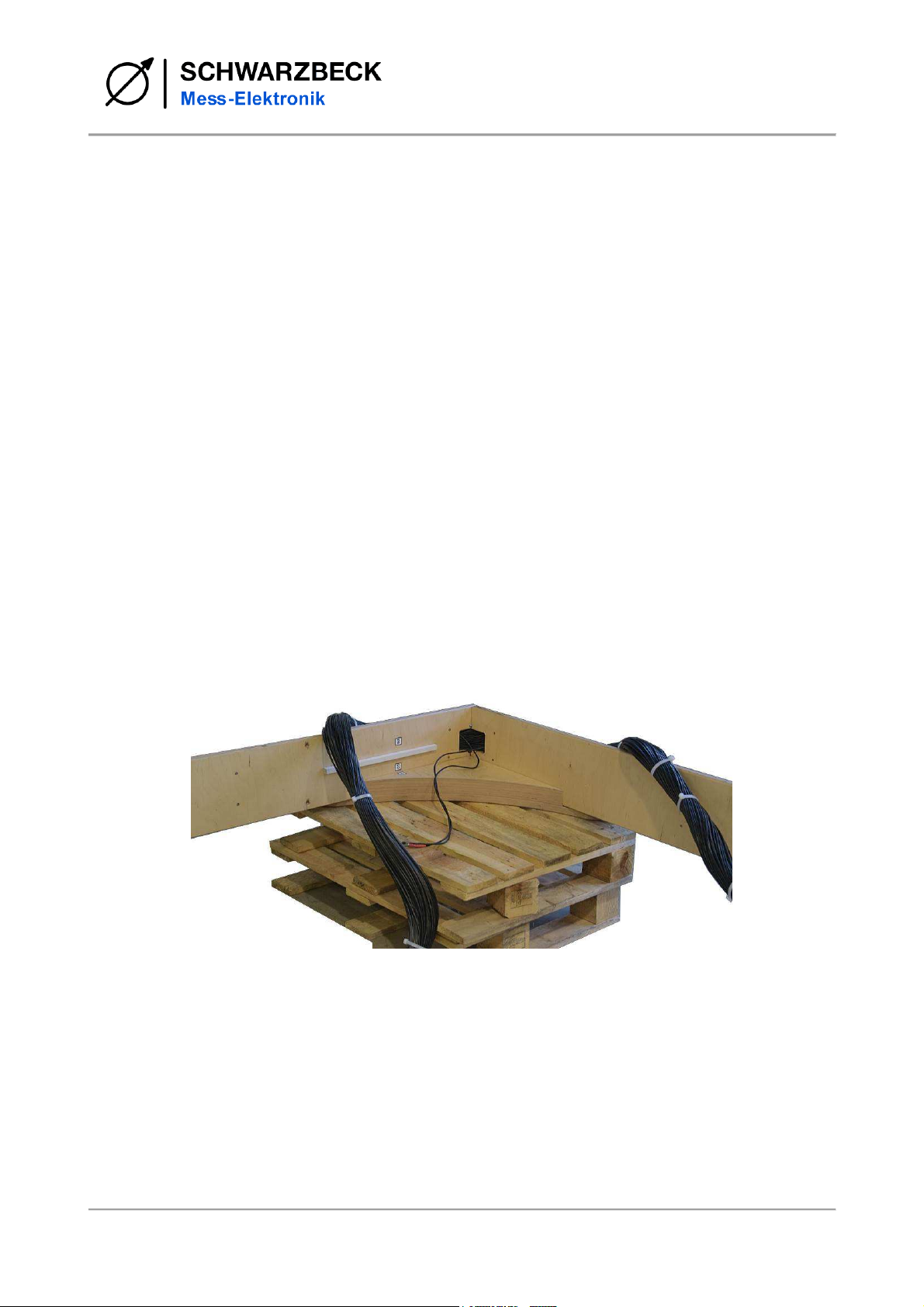
Beim Hantieren mit dem Kabelstrang muß sehr
vorsichtig vorgegangen werden, insbesondere ist
zu vermeiden, daß einzelne Windungen heraus-
gezogen bzw. die Isolierungen beschädigt wer-
den.
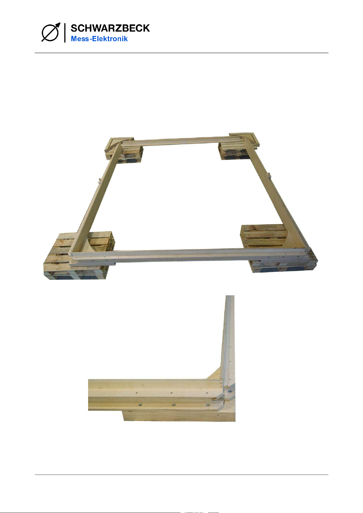
Nun wird das Kabelbündel ausgelegt und so aus-
gerichtet, daß die Kabelenden bei Ecke 01 in das
Innere des Spulenquadrats zeigen. Von außen
her, beginnend bei Ecke 01 wird das Kabelbündel
rundherum in den Windungskanal eingelegt und
falls nötig, mit etwas Schnur fixiert. Anschließend
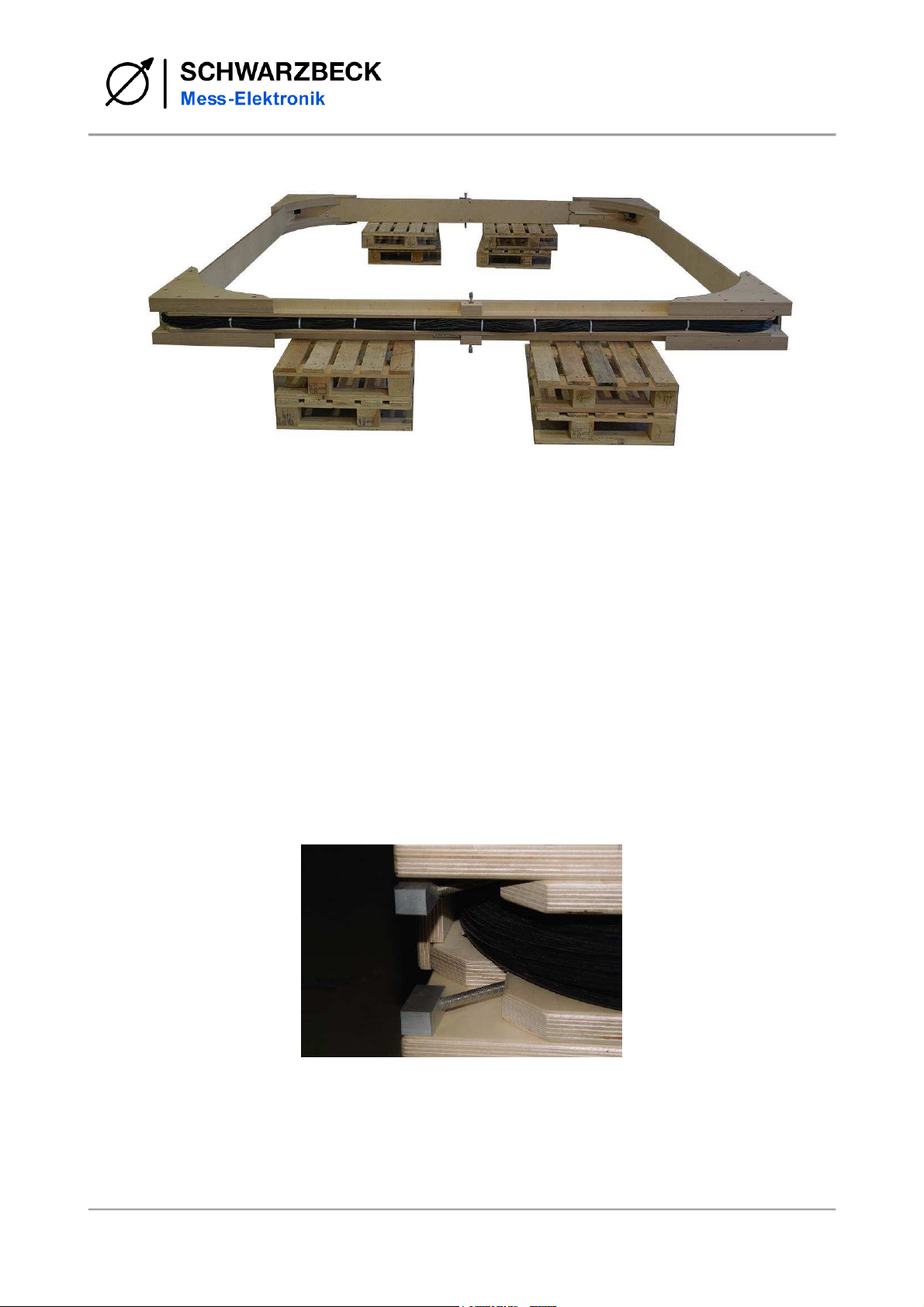
wird der Schenkel Top Coil 1 vom Inneren des
Quadrats nach Außen geschoben, um den Ka-
belstrang aufzunehmen und mit den beiden
Schenkeln Side A Coil 1 und Side B Coil 1 ver-
schraubt. Jetzt können Ecken 05 und 07 von
unten her eingelegt und mit jeweils 6 Schrauben
an den Seiten des Quadrats befestigt werden.
Nachdem alle vier unteren Eckwinkel angebracht
sind, werden die Eckwinkel 02, 04, 06 und 08 auf
der Oberseite aufgelegt und jeweils 6-fach ver-
schraubt. Das Windungspaket sollte nun mög-
lichst gleichmäßig verteilt und locker im Win-
dungskanal liegen.
The handling of the cable bundle requires
great care. It is especially important to
avoid that single turns are teared out of
the bundle. Further it is important not to
harm the isolation of the wires.
Now the cable bundle should be layed on
the ground and aligned in a way that the
end wires face towards the inner of the
coil square at Corner 01. Beginning at
Corner 01, the bundle is placed into the
legs of the square. Eventually some
strings can help to fix the cable bundle
inside the legs temporarily. Finally the leg
called Top Coil 1 is placed at the inside of
the square and moved into outwards di-
rection to pick up the bundle and to be
completed with Side A Coil 1 and Side B
Coil 1 with screws. Now the Corners 05
and 07 are placed under the square and
each of them is fixed with 6 screws. After
all four lower corners are fixed, the Cor-
ners 02, 04, 06, 08 are placed at the up-
per side of the square, each of them fixed
with 6 screws. The cable bundle should
be arranged uniformly throughout the
whole channel.
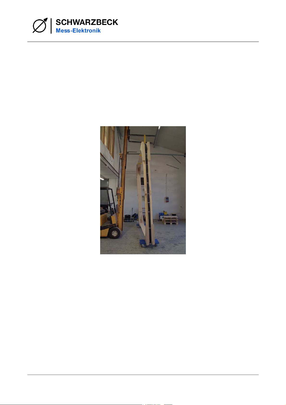
Cable bundle