6
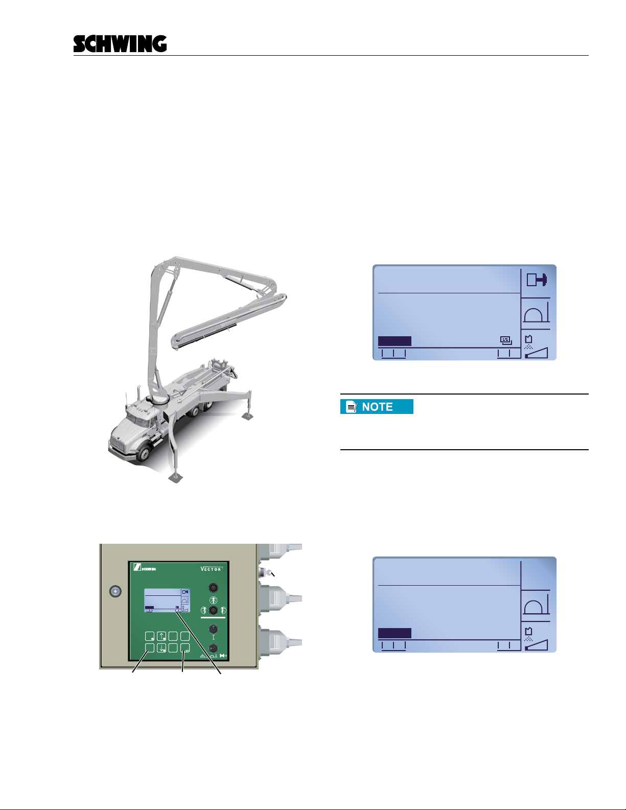
EASy Reference Guide - S38SX
Service Bulletin
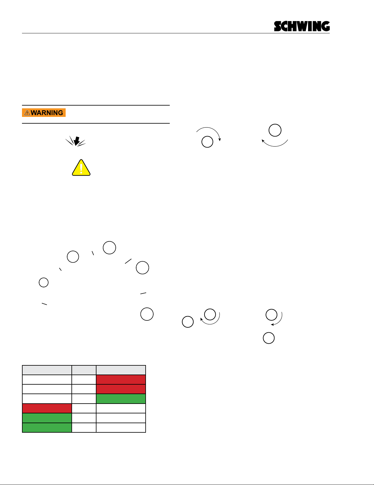
Calculating the Outrigger Load
After you nd an appropriate spot to set up the unit, you
must provide a stable base for the outriggers. If the site
you have chosen does not have stable soil conditions,
select a dierent site. Under no circumstances should
you compromise the stability of the unit by setting up on
unstable soil.
The following chart can be used as a guideline to help
you determine the load-bearing capacity of various soil
types. If you do not know what type of soil is on your job
site, the site manager may be able to tell you.
Soil Type PSI
Virgin ground 22
Asphalt 29
Compressed, crushed stone 36
Clay/silt soil, rm 43
Mixed granular soil 51
Firm, compacted gravel 58
Firm, compacted gravel (more compacted) 72
Firm, compacted gravel (more compacted,
class V)
109
Brittle, weathered rock 145
To determine the load your outriggers will impose on
the soil, divide the total force of the outrigger (shown on
a decal on the outrigger leg) by the number of square
inches of soil contact:
Soil pressure (PSI) = total outrigger force (lbs) ÷ area
of soil contact (sq. in.)
total outrigger force (lbs) =Soil pressure (PSI)
area of soil contact (sq. in.)
98419619
43,800 LBS
195 (KN)
MAX. OUTRIGGER LOAD
Figure 15
Outrigger load decal (located on outrigger leg)
Outrigger Calculations
The front outrigger decal on the S38SX shows a max-
imum force of 43,800 lbs. The steel outrigger pads are
9.4 inches in diameter (70 sq in.). Dividing 43,800 by 70
gives a soil pressure of 626 PSI:
43,800 (lbs) =626 (PSI)
70 (sq. in.)
As you can see from the Soil Type chart, the steel
pads are not big enough to be used by themselves on
any of the soil types listed. This is why the unit comes
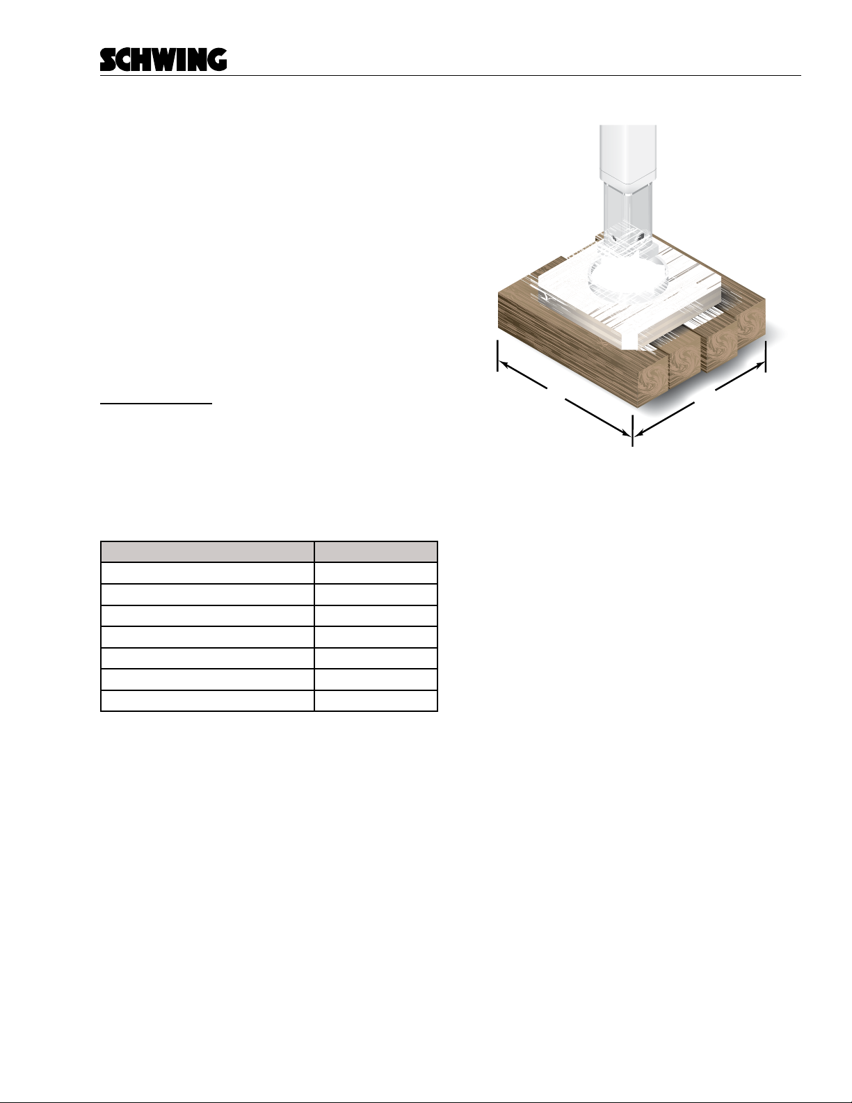
equipped with dunnage pads The pads are approxi-
mately 24” by 24” (576 sq in.). Now divide the maximum
force of 43,800 by 576:
43,800 (lbs) =76 (PSI)
576 (sq. in.)
The pressure of 76 PSI is suitable for rm, compacted
gravel (more compacted, class V). If you had to set up
on virgin ground, asphalt, or one of the other soil types
listed, you would need to use additional cribbing.
24”
24”
Figure 16
Dunnage Pads provided with unit.