FISBA READYBeam bio 1 Owner's manual

Technical Instruction
FISBA READYBeamTM
A compact multi-wavelength laser module
October 2021


Content
1 Safety 4
1.1 Explanation of symbols 4
1.1.1 General safety instructions 4
1.1.2 Laser safety 4
1.1.3 Laser area 4
1.2 Warning and information labels 6
1.3 Correctandspecieduseoftheunit 6
1.4 Warranty conditions 7
1.4.1 Limits of the warranty 7
2 Technical system 7
2.1 Laser module 7
2.2 Installation and commissioning 8
2.2.1 Unpacking and checking for visible damage 8
2.2.2 Installation 8
2.2.3 Operating the FISBA READYBeamTM 8
2.2.4 Software Setup 8
2.2.5 Software interface 9
2.2.6 Modulation mode 10
Appendix 12
Data sheet 14
4
1 Safety
1.1 Explanation of symbols
This symbol is used for all points in these operating instructions to which special
attention is to be paid so that all directives, regulations, instructions and the correct
work sequence are observed, and to prevent minor or serious damage to the laser
system or plant.
1.1.1 General safety instructions
The operating instructions and the safety instructions are to be read and observed
prior to installation and commissioning! The operating instructions must be read,
understood and followed by the operators responsible for the unit. Along with the
in structions in these operating instructions, also observe the generally applicable
safety and accident prevention regulations! All work on installation and commissioning
as well as all maintenance is to be performed by appropriately qualied personnel.
National accident prevention regulations, EN and IEC standards are to be observed.
Appropriately qualied personnel in the context of these basic safety instructions are
persons who are familiar with the tting, installation, placing in operation and operation
of the product and have qualications appropriate to their task.
1.1.2 Laser safety
The unit is a class 3B laser device. Both the direct beam and its reections from
di ffuse reective surfaces are dangerous.The unit emits strong power beams in the
visible spectral range (approx. 400 nm to 700 nm, for more detailed information see
the data sheet, page 14). The radiation can cause irreversible damage to the eyes if the
necessary protective measures are not taken.
1.1.3 Laser area
The laser area is the area in which the values for the maximum permissible irradiation
can be exceeded. Here the possibility of unintentional deection of the laser beam is
also to be taken into account. If operational equipment other than that given in this
manual or another procedure is used, dangerous exposure to the radiation may result.
Laser system screened inside a protective cover
By using suitable screening it can be ensured that people are not exposed to the laser
radiation. In this way the laser class is reduced and it is possible to work with the
closed arrangement without additional limitations or further measures.

5
However, in this case the following requirements apply to the protective cover:
· The protective cover must be appropriate to adequately shield the laser
radiation. It is therefore necessary to use laser safety glass or laser safety
lm for viewing windows.
· The cover itself as well as any doors or aps in the cover must be protected
using the interlock circuit that automatically shuts down and inhibits the laser
immediately on intentional or unintentional opening.
If the interlock circuit is disabled for service or maintenance work on the system with
the cover open, the laser area is enlarged again and the regulations in the next section
“Presence of persons in the laser area” apply.
Presence of persons in the laser area
In the laser area, people are subject to hazards, in particular ocular. Therefore the
follow ing measures must be taken and the following safety regulations observed:
· The room must have an emergency exit.
· The room must be optically screened from the environment (e.g. laser safety
lm on the windows).
· The laser area is to be kept as small as possible, to be bounded by suitable
screening and protected against access by unauthorized persons. The num-
ber of persons in the laser area should be reduced to the minimum.
· There must be a warning device on all entrances to the room that indicates
the laser radiation hazard.
· If the entry doors are not protected using the interlock circuits, opening the
doors easily from the outside must be impossible to prevent thoughtless
entry.
· All persons who are in the laser area during operation must be informed
about the dangers of the laser radiation.
· Laser safety glasses/goggles must be worn in the laser area. The operating
organisation must ensure that suitable safety glasses/goggles are available.
The glasses/goggles are selected in accordance with DIN EN 207. Please see
the data sheet on the unit for the actual wavelength of your laser. Herein-
after, the term safety glasses is always used to refer to suitable laser safety
glasses/goggles. Caution: in some circumstances your laser safety glasses/
goggles may not protect you from a powerful red pilot beam.
· There must not be any potentially explosive substances in the laser area.
Easily inammable substances may catch re.
· Glossy reective equipment must be either removed from the laser area or
covered. Windows and reecting walls are also to be covered with material
with low inammability.

6
1.2 Warning and information labels
The following warning labels are tted to laser and processing head:
The READYBeam is an OEM certied laser. Please be advised that it has no dedicated
Key Switch. If operated via PC with the software installed, be cautioned that sudden-
ly unplugging it during “Lasing,” will cause it to emit radiation when plugged in the
next time. Always make sure to turn it to the “off” position prior to shutting down the
computer.
1.3 Correctandspecieduseoftheunit
It is forbidden to commission the laser system until it has been ensured that the
ma chine or plant in which the laser system has been tted complies with the appli-
cable safety regulations. The organisation operating the plant is solely liable for any
damage caused by incorrect use of the unit. The organisation operating the system is
respon sible for the correct conditions in relation to operation, maintenance and repair.
The only personnel to be tasked with operation, maintenance and repair are personnel
who have been adequately instructed in the function of the laser system and who
have also been instructed specically on the dangers and risks of incorrect handling of
the system.
7
1.4 Warranty conditions
The warranty period is 12 months from delivery. The warranty covers the entire laser
module. The warranty will become void on the
· unauthorized opening of the unit‘s components
· operation of the unit in an unauthorized conguration
· improper use, storage or transport (e.g. vibration, temperature shock, the
action of frost)
1.4.1 Limits of the warranty
No warranty of the suitability of the product for specic applications is provided.
FISBA is not liable for indirect, direct or consequential damages caused by the use of
this product.
2 Technical system
The laser module emits laser radiation with different wavelengths. Combination of
different laser diodes can emit radiation in the UV, VIS and/or NIR range. The different
combinations are documented within the data sheet, see page 14.
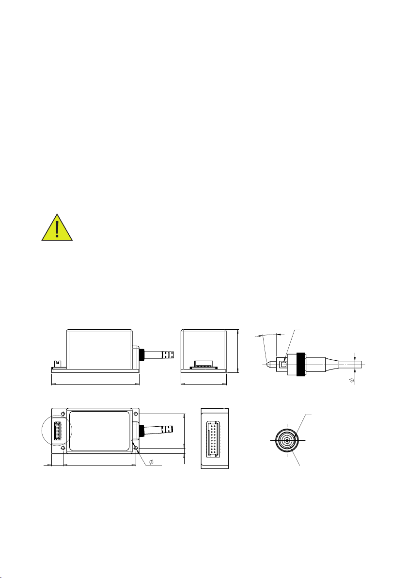
2.1 Laser module
Dimensions of the laser module in mm:
77 40
37
10 64
5
30
2.9
A
A
01
20 19
02
Pin assignment Samtec SFSD-10-28G24.00SR
01
VIN red N
11
RS485B
02
VIN red P
12
RS485A
03
VIN green N
13
GND
04
VIN green P
14
GND
05
VIN blue N
15
GND
06
VIN blue P
16
GND
07
GND
17
+12V...+24V
08
Enable red
18
+12V...+24V
09
Enable green
19
+12V...+24V
10
Enable blue
20
+12V...+24V
CAD-System: SolidWorks
00.237.83-010
SAP Material:
A4
Format
Format
www.fisba.com
1:1
Massstab
/ Scale
Werkstoff
Material
Änderungs-Nr.
Revision no.
Benennung
/ Description
1 / 1
Blatt / Anz
Sheet / no. of
Zeichnungs-Nr.
/ Drawing no.
Freigegeben
Approved
Erstellt
Prepared
READYBeam BIO
Streng vertraulich. Alle Rechte vorbehalten. Die Vervielfältigung
und die Verarbeitung mit elektronischen Systemen ist ohne
schriftliche Genehmigung der FISBA AG nicht gestattet.
Revision
Revision
+
E-18006
Gewicht
Weight
130.13 g
Geändert
Modified
Strictly confidential. All rights reserved. Reproduction and
processing of data in electronic systems or in any form whatever
is not permitted without written authority of FISBA AG.
Status
Status
in Bearbeitung
Oberfläche
Surface
Dimension nach Oberflächenbehandlung
Dimensions after surface treatment
Kanten gebrochen 0.1...0.2x45°
Edges chamfered 0.1...0.2x45°
Allgemeintoleranzen nach ISO2768-fH
General tolerances according to ISO2768-fH
Toleranz-Grundsatz nach ISO8015
Tolerancing ISO8015
Alle Masse in mm
All dimensions in mm
FC Connector Key
Laser Exit Aperture
8°
3
FC Connector Key
Narrow Key
Slow Axis Alignment
Polarisation Direction
FC Connector Key
Laser Exit Aperture
8°
3
FC Connector Key
Narrow Key
Slow Axis Alignment
Polarisation Direction
Connector: Samtec SFSD-10-28G24.00SR
Pin assignment: documented in the appendix (Table 1 on page 12)
8
2.2 Installation and commissioning
Note that the laser module with electronic driver is not a product for direct use.
Security elements, such as interlock, and emergency switch are not included in
the laser module. If the laser module is used as part of system or product, then the
responsibility for safety lies with the product development team of the product.
When operating the laser module, the laser safety regulations must be observed.
2.2.1 Unpacking and checking for visible damage
Check the completeness of the delivery and check that all the items supplied are in
good condition. In case of errors please contact FISBA AG (readybeam@sba.com).
If possible, keep the packaging in which the laser system was supplied. It will then
be possible to pack the unit in its original packaging and transport it safely in case of
repair.
2.2.2 Installation
The laser module can be mounted with screws on a at bottom plate. The bottom
plate should be cooled and the heat transfer should be at least 7W to hold the module
on a stable operating temperature. The laser module READYBeam is TEC-controlled.
Incorrect cooling effects the laser power and can destroy the laser diodes. During
assembly of the laser module on a plane cooling surface, attention is required so that
no tension can apply to the casing. Tension inuences the beam quality very strongly.
The connection must be handled carefully.
2.2.3 Operating the FISBA READYBeamTM
· The safety regulations must be carefully observed
· A power supply between +12 and +24V with max. 4 Ampere is needed
to start the READYBeam
· FISBA READYBeamTM can be started digital with the software application
and RS485 interface or analog based controlled
2.2.4 Software Setup
· Visit sba.com/readybeam-software to download the software
· Unpack the les from downloaded folder
· Start “RGB Service Software Setup.msi” and follow the
installation instructions
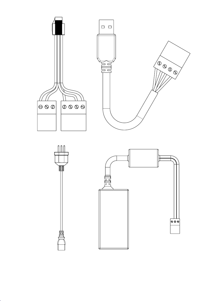
· You need an USB - RS485 interface cable for the digital operating mode
See the details in the appendix (Figure 1 on page 13)

9
· Connect the USB plug to your laptop and the RS485 plug to the laser module
interface cable
· Connect the power supply to the interface cable
· Connect the interface cable to the laser module connector
· Start the READYBeam software
· Now it is possible to control the lasers via the software
2.2.5 Software interface
The software interface allows a fast start up of the READYBeam with all main
functions.
· Connect power supply
· Connect RS485 interface cable
· Connect the interface cable to the READYBeam
· Switch On +12/+24V Power
· Start software
· Wait 1 minute for temperature stabilization
1. Set Modulation Mode: choose “Digital”
2. Set Power Value 1 (red), Power Value 2 (green) and Power Value 3 (blue):
values in % of the max. laser power
3. Switch the Laser on/off with Digital Enable 1, 2 or 3
4. Enter the command with “WriteCong”Button
The READYBeam software is provided for download at:
sba.com/readybeam-software

10
2.2.6 Modulation mode
On the Interface, the three channels can be set as either on “Digital” to control
On/Off modulation via software with a maximum pulse frequency of 100 Hz, or
to “Analog” for external control in On/Off mode or continuous waveform modulation.

11
Software Control External Control
Digital
On/Off
modulation
Up to 100Hz
Analog
On/Off
modulation
Up to 1M Hz
Continuous
waveform
Up to 20kHz
On/Offmodulation
On/Off modulation is best when the operator wants fast and accurate modulation with
discrete signals. Digital modulation is possible with two options. Option one is over
the SW up to 100Hz. Option two over a 0-3.3V TTL input signal up to 1MHZ. For digital
modulation over SW, choose “Digital” from the “Modulation Mode” drop-down menu
on the main screen and set “Pulse Enable” to ON and set “On Time “ and “Off Time”.
The unit of On and Off Time is ms. For digital modulation over TTL input signal, choose
“Analog” from the “Modulation Mode” drop-down menu on the main screen and use
a function generator or a similar external signal source for the 0-3.3V TTL input Signal.
A function generator, or similar external signal source, is needed to drive the modula-
tion.
Continuous waveform
To modulate the laser power choose “Analog” from the “Modulation Mode” drop-
down menu. The signal is calibrated from 0.33V to 3.3V. This corelates with 10% to
100% of laser power. Below 0.33V the laser power is not longer linear and below the
threshold current the laser is no longer in lasing mode. A function generator, or similar
external signal source, is needed to drive the modulation.

12
Appendix
Pin conguration and power values
Connector: Samtec SFSD-10-28G24.00SR
Enable Laser: low = 0V, high = 3.3V
Analog In: 0.33V … 3.3V --> 10% ...100% of Laser power
Power: +12V … + 24V max. 4A
Pin 1 is marked on the connector with arrow (not notch)
Pin 1 Analog In- Laser red
Pin 2 Analog In+ Laser red
Pin 3 Analog In- Laser green
Pin 4 Analog In+ Laser green
Pin 5 Analog In- Laser blue
Pin 6 Analog In+ Laser blue
Pin 7 Gnd
Pin 8 Enable Laser red
Pin 9 Enable Laser green
Pin 10 Enable Laser blue
Pin 11 RS 485 B
Pin 12 RS 485 A
Pin 13 Gnd
Pin 14 Gnd
Pin 15 Gnd
Pin 16 Gnd
Pin 17 Power +12V … +24V
Pin 18 Power +12V … +24V
Pin 19 Power +12V … +24V
Pin 20 Power +12V … +24V
Table 1
13
USB RS-485
Power RS-485
Module
Power
Power supply
Electric
Cable
Figure 1

14
Data sheet FISBA READYBeamTM
Technical Specications
FISBA READYBeam™
Technical specications
Wavelength 1)
405 nm 450 nm 488 nm 520 nm 638 nm 660 nm
FISBA READY BeamTM bio 1 1006061 xxx
FISBA READY BeamTM bio 2 1008062 xxx
FISBA READY BeamTM ind 1 1006062 xxx
FISBA READY BeamTM ind 2 1007773 x x x
Output power calibrated values 2) 40 mW 40 mW 30 mW 30 mW 40 mW 40 mW
Power stability 8 h < 2%
Fiber type SM/PM, 3 µm core, end capped, APC Connector
Fiber cable length 1 m
Polarisation ratio 3) typ.17 dB
Spatial mode TEM 00
M2 < 1.1
Optical noise RMS, 20Hz – 20MHz typ. 0.2, max. 0.5 %
Laser operation modes CW, modulated
Digital modulation TTL input
Digital modulation frequencies 1 MHz
Digital rise time 10 – 90% 11 ns
Digital fall time 90 – 10% 11 ns
Analog modulation bandwidth 0 – 3.3 V input voltage
Analog modulation frequencies 20 KHz
Analog rise time 10 – 90% 12 µsec
Analog fall time 90 – 10% 12 µsec
Laser safety class 3B
Max. storage temperature range - 10° C to + 60° C
Operational temperature range + 15° C to + 40° C
Power consumption typ. 5 W, max. 12 W
Temperature stabilization internal TEC controlled
Communication interface RS 485
1)
Laser center wavelength tolerances: 405: 400 – 410nm ; 450: 440 – 460nm; 488: 486 – 490nm; 520: 515 – 530 nm; 638: 632 – 643nm; 660: 655 – 665nm
2)
linear calibrated power range from 10% to 100% (max)
3)
min.13dB, max. 26 dB

15
Denition of QR Code information
Specication1 Itemnumber
Specication2 Serialnumber
Specication3 Finalinspectiondate
CAD-System: SolidWorks
SAP Material:
A4
Format
Format
www.fisba.com
1:1
Massstab
/ Scale
Werkstoff
Material
Änderungs-Nr.
Revision no.
Benennung
/ Description
1 / 1
Blatt / Anz
Sheet / no. of
Zeichnungs-Nr.
/ Drawing no.
Freigegeben
Approved
Erstellt
Prepared
Streng vertraulich. Alle Rechte vorbehalten. Die Vervielfältigung
und die Verarbeitung mit elektronischen Systemen ist ohne
schriftliche Genehmigung der FISBA AG nicht gestattet.
Revision
Revision
Gewicht
Weight
99.09 g
Geändert
Modified
Strictly confidential. All rights reserved. Reproduction and
processing of data in electronic systems or in any form whatever
is not permitted without written authority of FISBA AG.
Status
Status
in Bearbeitung
Oberfläche
Surface
Dimension nach Oberflächenbehandlung
Dimensions after surface treatment
Kanten gebrochen 0.1...0.2x45°
Edges chamfered 0.1...0.2x45°
Allgemeintoleranzen nach ISO2768-fH
General tolerances according to ISO2768-fH
Toleranz-Grundsatz nach ISO8015
Tolerancing ISO8015
Alle Masse in mm
All dimensions in mm
READYBeam Front View - mit Labels
i

© FISBA AG

FISBA AG
FISBA Photonics GmbH
FISBA LLC
FISBA (Shanghai) Co., Ltd.
Rorschacher Str. 268
9016 St.Gallen
Switzerland
Schwarzschildstrasse 10
12489 Berlin
Germany
6296 E.Grant Rd Suite 150
Tucson, AZ 85712
United States
World Plaza, No. 855
9F Pudong South Rd.
Puong District
Shanghai City
China
sba.com |readybeam@sba.com
This manual suits for next models
7
Table of contents


