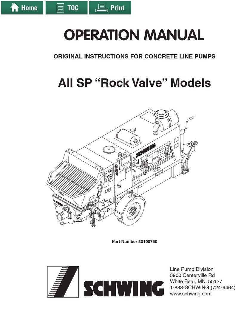
Schwing SP 500 User manual

Operation Manual
SP 500 / 750-15 / 750-18 / 1000 / 1250
Part# 98418850
Revision: 1.1
Date: 02/13/17
5900 Centerville Road
St. Paul, MN 55127
1-888-SCHWING (724-9464)
www.schwing.com

CALIFORNIA
PROPOSITION 65 WARNING
Diesel engine exhaust and some of its
constituents are known to the State of
California to cause cancer, birth defects,
and other reproductive harm.

Operation Manual
SP 500 / 750-15 / 750-18 / 1000 / 1250
Copyright © 2017, Schwing America, Inc. All rights reserved
Part# 98418850
Revision: 1.1
Date: 02/13/17


5
Table of Contents
SP 500 / 750-15 / 750-18 / 1000 / 1250 Operation Manual
Table of Contents
Introduction................................................ 9
Manufacturer’s Statement ................................ 11
Concrete Pump Nomenclature .........................12
Identication Tag (ID Tag).................................12
How to order missing tags.............................13
Specications .......................................... 15
Concrete Pump Specications .........................17
SP 500...........................................................17
SP 750-15......................................................18
SP 750-18......................................................19
SP 1000.........................................................20
SP 1000HP....................................................21
SP 1250.........................................................22
Optional Equipment..........................................23
Safety........................................................ 25
Safety Alert Symbols ........................................27
Safety Manual...................................................28
How to Order Additional Safety Manuals.......28
Schwing phone numbers...............................28
Warning Labels (Decals) ..................................28
Product Overview.................................... 31
Concrete Pump Circuit Overview ..................31
Twin-circuit switching vs Single-circuit..............32
Safety Devices..................................................34
Emergency Stop Buttons (E-Stop) ................34
Dump Valve ...................................................34
Emergency Stop (E-Stop) manifold...............35
Hopper Grate Interlock Switch.......................35
Manual Bleed-O Valve.................................36
Pressure Relief Valves ..................................36
Safety guards ................................................36
Warning Horn.................................................37
Machine Overview............................................38
Pumpkit Overview..........................................39
S1/S2/S3 Control Valve .................................40
Accumulator / Accumulator Manifold .............40
Waterbox .......................................................40
Hopper...........................................................41
Fuel Tanks .....................................................41
Power Pack ...................................................41
SCT (Schwing Control Technology)..................42
HMI (Human Machine Interface) ......................43
Navigation Pane ............................................43
LCD Screens ....................................................44
Start up Screen..............................................44
Engine Status Screen....................................44
Warning Messages and Symbols ..................44
Warning Messages........................................45
E-stop Warnings ............................................45
General Warnings..........................................45
Pump Status Screen......................................46
Menu Screen .................................................46
Pump Codes Screen .....................................46
Engine Codes Screen....................................47
PLC I/O Screen .............................................47
Operator Keypad Screen...............................47
Radio Remote Screen ...................................47
Cable Remote Screen ...................................47
Options Screen..............................................48
Oil temperature Sensor Settings Screen.......48
Greaser Settings Screen ...............................48
Stroke Limit Settings Screen .........................49
Language Screen ..........................................49
Machine Options Screen ...............................49
Operator Panel Keypad....................................50
Keypad Buttons ................................................50
Cable Remote...................................................53
Keypad Buttons ................................................53
Radio Remote (Optional)..................................56
Radio Remote Buttons and Lights....................57
Concrete Pump Error Codes ............................59
Pump Codes Screen .....................................59
Input Error Codes ..........................................59
Output Error Codes .......................................59
Error Cause ...................................................59

6
Table of Contents
SP 500 / 750-15 / 750-18 / 1000 / 1250 Operation Manual
Operation.................................................. 61
Preparing for the Job........................................63
Personal Protection .......................................63
Pipeline and Clamps......................................63
Tools and Accessories...................................63
Tow Vehicle....................................................64
Tow Vehicle Pre-Check..................................64
Stationary Pump Pre-Check ..........................64
Attaching the Tow Hitch .................................65
Towing the Stationary Pump..........................66
Machine Loading/Unloading.............................67
Lifting with a Crane........................................67
Lifting with a Forklift.......................................67
Loading on a atbed trailer............................67
Unit Setup.........................................................67
Selecting the setup location ..........................67
Laying out the pipeline...................................68
Machine Preparation .....................................68
Starting the Machine.........................................70
Checking the machine...................................70
Shutting the Machine Down..............................71
Lubricating Slurry..............................................71
Lubricating the pipeline..................................71
Controlling the Concrete Pump ........................74
Stroke Limiter ................................................74
Cable Remote................................................74
Wireless Remote (Optional) ..........................75
Safe pairing of Transmitter to Receiver .........75
Pumping the Job...............................................77
Time constraints ............................................78
Cold conditions ..............................................78
Delays............................................................78
Keep the water box full ..................................78
Blockages......................................................79
Cleanout ...........................................................80
Clean the waterbox........................................83
Preparing for travel........................................83
External Cleaning .............................................84
High Pressure Washer...................................84
Use of Cleaning Agents.................................84
Protecting New Paint.....................................84
Special Pumping Situations..............................85
Quick cleanout...............................................85
Cold-weather pumping ..................................85
Emergency Procedures....................................87
Emergency Override Button ..........................87
Loss of Radio/Cable remote..........................87
Optional Equipment..........................................88
Hydraulic Outriggers......................................88
Hopper Vibrator .............................................88
Auto Greaser .................................................88
Maintenance............................................. 89
Hoses and Fittings............................................91
Torque specications .....................................91
Welding precautions......................................91
Adjusting relief valves....................................91
Removing safety devices...............................92
Lock Out - Tag Out procedure .......................92
Replacing the hydraulic pump .......................92
Hydraulic Oils ...................................................93
General information .......................................93
Specic information .......................................93
“Industrial” gear lubricant codes ...................93
Vehicle gear box oil codes.............................93
Hydraulic Oil Recommendations ...................94
Biodegradable Hydraulic Oils ...........................94
Filtration............................................................95
General information .......................................95
Specic information .......................................95
Bypass Check valve ......................................96
Scheduled Maintenance...................................97
Maintenance Chart ........................................97
Daily maintenance............................................98
Weekly maintenance ......................................101
Monthly maintenance .....................................103
Semi-annual maintenance .............................104

7
Table of Contents
SP 500 / 750-15 / 750-18 / 1000 / 1250 Operation Manual
Annual maintenance.......................................105
Change hydraulic oil for age reasons..........105
Unscheduled maintenance.............................105
Changing rams ............................................105
Ram Change Mode .....................................105
Remove the old rams ..................................106
Install the new rams.....................................108
Changing the Material Cylinders ................. 110
Accumulator Charging Procedure ............... 110
Setting main relief / Pressure cut o............ 113
Setting the soft switch relief pressure ......... 114
Set accumulator pressure cut-o................. 115
Set the agitator pressure. ............................ 115
Appendix ................................................ 117
Hydraulic Oil Viscosity Chart .......................... 119
Torque Specications for Metric Bolts ............120
Torque Chart...................................................121
Dacromet/Geomet 500 Coating...................121
Torque Chart...................................................122
Black and Silver Chromated........................122
Recommended Emergency Hose Kit .............123
Fitting Wrench Sizes.......................................123
Straight ttings.............................................123
Banjo ttings...................................................124
End Cap Separate from Stem .....................124
End Cap Part of Stem..................................124
Weld-on Ends / Coupling Comparison ..........125
Minimum Pipe Wall Thickness........................126
Single Wall...................................................126
Minimum Pipe Wall Thickness........................127
Twin Wall .....................................................127
Output Charts .................................................128
Using a Nomograph........................................134
The quadrants .............................................136
Glossary of Terms...........................................141
Additional Reading Material............................145
Alphabetical Index................................. 147
Short Instructions.................................. 151
Preparation.....................................................153
Starting the Machine.......................................153
Checking the machine.................................154
Shutting the Machine Down............................154
Controlling the Concrete Pump ......................155
Stroke Limiter ..............................................155
Cable Remote.................................................155
Cable Remote Functions .............................156
Radio Remote (Optional)................................156
Radio Remote Functions .............................157
Emergency Procedures..................................158
Emergency Override Button ........................158
Loss of Radio/Cable remote........................158


9
Introduction
SP 500 / 750-15 / 750-18 / 1000 / 1250 Operation Manual
Manufacturer’s Statement .............................11
Concrete Pump Nomenclature......................12
Identication Tag (ID Tag)..............................12
How to order missing tags.............................13
Introduction


11
Introduction
SP 500 / 750-15 / 750-18 / 1000 / 1250 Operation Manual
Manufacturer’s Statement
Schwing America is a member of the Schwing Group,
a worldwide designer, manufacturer and distributor of
premium concrete production and handling equipment,
headquartered in Herne, Germany. Schwing, commit-
ted to supporting its customers’ success, excels in pro-
ducing high quality concrete equipment used in even
the most demanding construction applications, through
innovative engineering, premiere manufacturing and
optimum after-sales support. Schwing America, located
in St. Paul, Minnesota, oers industry leading concrete
pumps, truck mixers, batch plants, reclaimers and gen-
uine parts for distribution in North and Latin America.
The information contained in this operation manual is
absolutely necessary for the setup, operation, mainte-
nance, and servicing of your concrete pump. All opera-
tors should become familiar with the information in this
manual as it will promote safety, eciency of operation
and long life of the equipment. Keep this manual and
all included literature in a safe and convenient location.
Read and understand this manual before operating, re-
pairing, or adjusting your Schwing concrete pump. The
individuals who operate and maintain it must be trained
and have knowledge of the equipment. Death or severe
injury can occur if this equipment is misused or poorly
maintained.
The illustrations contained in this manual are intended
to clarify text passages. They may look slightly dier-
ent from your concrete pump, but this has only been
allowed if it does not fundamentally change the factual
information.
Technical modications that are made to this machine
will be documented in each new edition of the operation
manual.

12
Introduction
SP 500 / 750-15 / 750-18 / 1000 / 1250 Operation Manual
Concrete Pump Nomenclature
The complete model number of a Schwing
concrete pump is designated by the following
code:
SP 750-18
90/50 x 1000:180
The code is broken down as follows:
Stationary Pump
Model Number
18 cm Diameter Material Cylinder Bore
SP 750 18
Pumpkit90 / 50 x 1000 : 180
Differential Cylinder
Bore Diameter
90mm
Differential Cylinder Rod Diameter
50mm
Differential Cylinder Stroke Length
1000mm
Material Cylinder Bore Diameter
180mm
How to reach us
If you encounter a circumstance that is not covered by
this manual, Schwing America’s Service Center will be
more than happy to assist you with all of your parts and
service needs.
• Service Center 1-888-292-0262
• Spare Parts 1-800-328-9635
• Spare Parts FAX (651) 429-2112
• Minnesota (main oce) (651) 429-0999
To place an order for spare parts, go online to
Schwingparts.com, or call our toll free parts line from
anywhere in the continental United States. Spare Parts
hours are Monday through Friday, 6:00 AM to 6:00 PM
(central time). Orders will also be accepted via fax, 24
hours/day.
When contacting the Service Center please provide the
concrete pump model and serial number. You can nd
the model and serial number on the Main ID tag that is
mounted to the subframe of the unit (Figure 2).
Identication Tag (ID Tag)
The ID tag (Figure 1) lists the model and serial number
of the concrete pump. This tag also provides informa-
tion on the pumpkit, weights, year of manufacture, ma-
terial and hydraulic system pressures.
ID tags and serial numbers shown in this manual
are for “REFERENCE ONLY”. Locate each of the
tags on your own unit to determine specic infor-
mation for your pump.
98380587 02
SUBSIDIARY OF
SUBSIDIARIA DE
Schwing America
5900 Centerville Rd
White Bear, MN 55127
Phone:
651-429-0999
www.schwing.com
Schwing Gmbh
Heerstrasse 9-27
D-44653 Herne / Germany
Phone +49-2325-987-0
www.schwing.de
This product is covered by one or more U.S. patents - see patent decal /Este producto está cubierto por una o más patentes de Estados Unidos-vea la etiqueta
MODEL
MODELO
SERIAL #
# DE SERIE
YEAR
ANO
MAX
SPM
Concrete
Pump / Bomba
De Concreto
Agitator
El Agitador
Accumulator
El Acumulador
Auxiliary
Auxiliar
P.S.I.
bar
P.S.I.
bar
P.S.I.
bar
P.S.I.
bar
P.S.I.
bar
Tongue Weight
Lengua De Peso
Allowable Vertical Tongue Load
Carga Vertical Permisible
Allowable Horizontal Tongue Load
Carga Horizontal Permisible
HP
kW
Material
WEIGHTS/LOADS/PESO/CARGA
HYDRUALIC PRESSURES/PRESIONES HIDRAULICAS MATERIAL PRESSURE/PRESIONES
LBS
N
LBS
N
LBS
N
Total Weight
Peso Total
LBS
N
RS
RS
PS
PS
Figure 1
ID Tag

13
Introduction
SP 500 / 750-15 / 750-18 / 1000 / 1250 Operation Manual
How to order missing tags
If ID tags are missing or have been removed, you can
order new tags through Schwing America’s Service
Center. Simply provide the serial number of your con-
crete pump and new ID tags can be created. The serial
number is punched into the steel subframe near the ID
Tag (Figure 2).
Figure 2
ID Tag Location
98380587 02
SUBSIDIARY OF
SUBSIDIARIA DE
Schwing America
5900 Centerville Rd
White Bear, MN 55127
Phone:
651-429-0999
www.schwing.com
Schwing Gmbh
Heerstrasse 9-27
D-44653 Herne / Germany
Phone +49-2325-987-0
www.schwing.de
This product is covered by one or more U.S. patents - see patent decal /Este producto está cubierto por una o más patentes de Estados Unidos-vea la etiqueta
MODEL
MODELO
SERIAL #
# DE SERIE
YEAR
ANO
MAX
SPM
Concrete
Pump / Bomba
De Concreto
Agitator
El Agitador
Accumulator
El Acumulador
Auxiliary
Auxiliar
P.S.I.
bar
P.S.I.
bar
P.S.I.
bar
P.S.I.
bar
P.S.I.
bar
Tongue Weight
Lengua De Peso
Allowable Vertical Tongue Load
Carga Vertical Permisible
Allowable Horizontal Tongue Load
Carga Horizontal Permisible
HP
kW
Material
WEIGHTS/LOADS/PESO/CARGA
HYDRUALIC PRESSURES/PRESIONES HIDRAULICAS MATERIAL PRESSURE/PRESIONES
LBS
N
LBS
N
LBS
N
Total Weight
Peso Total
LBS
N
RS
RS
PS
PS
9838058702
SUBSIDIARYOF
SUBSIDIARIADE
SchwingAmerica
5900CentervilleRd
WhiteBear,MN55127
Phone:
651-429-0999
www.schwing.com
SchwingGmbh
Heerstrasse9-27
D-44653Herne/Germany
Phone+49-2325-987-0
www.schwing.de
Thisproductiscovered by one or more U.S. patents - see patent decal /Este producto está cubierto por una o más patentes de Estados Unidos-vea la etiqueta
MODEL
MODELO
SERIAL#
#DESERIE
YEAR
ANO
MAX
SPM
Concrete
Pump/Bomba
DeConcreto
Agitator
ElAgitador
Accumulator
ElAcumulador
Auxiliary
Auxiliar
P.S.I.
bar
P.S.I.
bar
P.S.I.
bar
P.S.I.
bar
P.S.I.
bar
TongueWeight
LenguaDePeso
AllowableVerticalTongueLoad
CargaVerticalPermisible
AllowableHorizontalTongueLoad
CargaHorizontalPermisible
HP
kW
Material
WEIGHTS/LOADS/PESO/CARGA
HYDRUALICPRESSURES/PRESIONESHIDRAULICAS MATERIALPRESSURE/PRESIONES
LBS
N
LBS
N
LBS
N
TotalWeight
PesoTotal
LBS
N
RS
RS
PS
PS

14
Introduction
SP 500 / 750-15 / 750-18 / 1000 / 1250 Operation Manual

15
Specications
SP 750-15 / 750-18 / 1000 / 1250 Operation Manual
Concrete Pump Specications......................17
SP 500...........................................................17
SP 750-15......................................................18
SP 750-18......................................................19
SP 1000.........................................................20
SP 1000HP....................................................21
SP 1250.........................................................22
Optional Equipment .......................................23
Specications


17
Specications
SP 750-15 / 750-18 / 1000 / 1250 Operation Manual
Concrete Pump Specications
SP 500
Concrete Pumpkit 80/50 x 1000:150
Concrete Valve Long Rock
Maximum Strokes/minute 32.5
Maximum Concrete Volume 45 cu. yd3/hr 35 cu. m3/hr
C4.4 Tier 3 - Diesel Motor 80 hp 60 Kw
C3.4 Tier 4 - Diesel Motor 74.5 hp 55.5 Kw
Electric Motor 75 hp 56 Kw
Output - Hydraulic Pumps 65 gpm 240 L/min
Hydraulic Pumps RPM- Diesel 2200 rpm
Hydraulic Pumps RPM- Electric 1800 rpm
Maximum Hydraulic Pressure 3872 psi 267 bar
Maximum Pressure on Concrete 1100 psi 75.8 bar
Maximum Aggregate Size 1.5” 38.1 mm
Pumping Cylinder Diameter 6” 152.4 mm
Stroke Length 39“ 990.6 mm
Dierential Cylinder Diameter 3” 80 mm
Charging Hopper Height 50.5” 1280 mm
Fuel Tank Capacity 33.5 gal. 127 L
Hydraulic Tank Capacity 53 gal. 200 L
Gross Weight N/A N/A
Length 186” 4712 mm
Width 72” 1833 mm
Height (Tier 3) 82” 2080 mm
Height (Tier 4) 88” 2226 mm
Remote Control Cable Length 100’ 30.5 m
* Max RPM of the hydraulic pumps is calculated while the pump is under a full load. Depending on the unit it is ac-
ceptable for the max RPM to vary slightly from the published estimate.

18
Specications
SP 750-15 / 750-18 / 1000 / 1250 Operation Manual
SP 750-15
Concrete Pumpkit 80/50 x 1000:150
Concrete Valve Long Rock
Maximum Strokes/minute 35
Maximum Concrete Volume 50 cu. yd3/hr 38 cu. m3/hr
C4.4 Tier 3 - Diesel Motor 100 hp 75 Kw
C3.4 Tier 4 - Diesel Motor 100 hp 75 Kw
Electric Motor 100 hp 75 Kw
Output - Hydraulic Pumps 65 gpm 240 L/min
Hydraulic Pumps RPM- Diesel 2200 rpm
Hydraulic Pumps RPM- Electric 1800 rpm
Maximum Hydraulic Pressure 3872 psi 267 bar
Maximum Pressure on Concrete 1100 psi 75.8 bar
Maximum Aggregate Size 1.5” 38.1 mm
Pumping Cylinder Diameter 6” 152.4 mm
Stroke Length 39“ 990.6 mm
Dierential Cylinder Diameter 3” 80 mm
Charging Hopper Height 51” 1292 mm
Fuel Tank Capacity 40 gal. 150 L
Hydraulic Tank Capacity 112 gal. 424 L
Gross Weight N/A N/A
Length 197” 4997 mm
Width 76” 1929 mm
Height (Tier 3) 96” 2438 mm
Height (Tier 4) 102” 2590 mm
Remote Control Cable Length 100’ 30.5 m
* Max RPM of the hydraulic pumps is calculated while the pump is under a full load. Depending on the unit it is ac-
ceptable for the max RPM to vary slightly from the published estimate.

19
Specications
SP 750-15 / 750-18 / 1000 / 1250 Operation Manual
SP 750-18
Concrete Pumpkit 90/50 x 1000:180
Concrete Valve Long Rock
Maximum Strokes/minute 35
Maximum Concrete Volume 70 cu. yd3/hr 53.5 cu. m3/hr
C4.4 Tier 3 - Diesel Motor 100 hp 75 Kw
C3.4 Tier 4 - Diesel Motor 100 hp 75 Kw
Electric Motor 100 hp 75 Kw
Output - Hydraulic Pumps 65 gpm 240 L/min
Hydraulic Pumps RPM- Diesel 2200 rpm
Hydraulic Pumps RPM- Electric 1800 rpm
Maximum Hydraulic Pressure 4350 psi 300 bar
Maximum Pressure on Concrete 1100 psi 75.8 bar
Maximum Aggregate Size 1.5” 38.1 mm
Pumping Cylinder Diameter 7” 177.8 mm
Stroke Length 39“ 990.6 mm
Dierential Cylinder Diameter 3.5” 90 mm
Charging Hopper Height 51” 1292 mm
Fuel Tank Capacity 40 gal. 150 L
Hydraulic Tank Capacity 105 gal. 400 L
Gross Weight 9320 lbs. 41.4 kN
Length 200” 4840mm
Width 76” 1835 mm
Height (Tier 3) 96” 2438 mm
Height (Tier 4) 102” 2590 mm
Remote Control Cable Length 100’ 30.5 m
* Max RPM of the hydraulic pumps is calculated while the pump is under a full load. Depending on the unit it is ac-
ceptable for the max RPM to vary slightly from the published estimate.

20
Specications
SP 750-15 / 750-18 / 1000 / 1250 Operation Manual
SP 1000
Concrete Pumpkit 90/50 x 1000:180
Concrete Valve Long Rock
Maximum Strokes/minute 35
Maximum Concrete Volume 70 cu. yd3/hr 53.5 cu. m3/hr
Diesel Motor (C4.4 Tier 3) 139 hp 104 Kw
Diesel Motor (C4.4 Tier 4) 137 hp 102 Kw
Electric Motor 125 hp 93 Kw
Output - Hydraulic Pumps 65 gpm 240 L/min
Hydraulic Pumps RPM- Diesel 2200 rpm
Hydraulic Pumps RPM- Electric 1800 rpm
Maximum Hydraulic Pressure 4350 psi 300 bar
Maximum Pressure on Concrete 1100 psi 75.8 bar
Maximum Aggregate Size 1.5” 38.1 mm
Pumping Cylinder Diameter 7” 177.8 mm
Stroke Length 39“ 990.6 mm
Dierential Cylinder Diameter 3.5” 90 mm
Charging Hopper Height 51” 1292 mm
Fuel Tank Capacity 40 gal. 150 L
Hydraulic Tank Capacity 105 gal. 400 L
Gross Weight 9150 lbs. 40.7 kN
Length 200” 4840mm
Width 76” 1835 mm
Height (Tier 3) 96” 2440 mm
Height (Tier 4) 94” 2400 mm
Remote Control Cable Length 100’ 30.5 m
This manual suits for next models
4
Table of contents
Other Schwing Water Pump manuals
Popular Water Pump manuals by other brands

Jung Pumpen
Jung Pumpen MULTICUT G2D-01 Installation and operator's manual

PSG Dover
PSG Dover WILDEN P100 Advanced Plastic Engineering, operation & maintenance

Grundfos
Grundfos CHI Series Installation and operating instructions

CleanCraft
CleanCraft DWS 1105 Operation instructions

DAB
DAB FK Instruction for installation and maintenance

RIDGID
RIDGID SEP-500 manual