TxIsoRail 4-20 mA
ISOLATED TEMPERATURE TRANSMITTER – OPERATION MANUAL V1.0x H
SPECIFICATIONS
Senso
r
inpu
t
:
Use
r
defined.
The
suppo
r
ted
senso
r
s
a
r
e
listed
in
Table
1
,
along
with
thei
r
maximum
r
anges.
The
r
mocouples
:
Types
J,
K,
R,
S,
T,
N,
E
and
B
to
IEC
60584
(
ITS
-
90
)
.
Impedance
>>
1
M
Ω
P
t
100
:
Excitation:
180
µ
A,
2
o
r
3
-
wi
r
e
connection
(
fo
r
2
-
wi
r
e
senso
r
s,
tie,
te
r
minals
2
and
3
togethe
r)
.
α
=
0.00385,
acco
r
ding
to
IEC
60751
(
ITS
-
90
)
.
Vol
t
age
:
0
to
50
mVdc,
0
to
10
Vdc.
Impedance
>>
1
M
Ω
.
*
No
t
e
:
0
-
10
Vdc
input
type
r
equi
r
es
an
inte
r
nal
jumpe
r
switching.
0
to
20
mA,
4
to
20
mA.
Impedance
15.0
Ω
(
+
1.9
Vdc
)
.
CONFIGURATION
If
the
t
r
ansmitte
r
is
al
r
eady
configu
r
ed
as
r
equi
r
ed
by
the
application
(
senso
r
type,
r
ange,
etc
)
,
it
may
be
installed
and
used
r
ight
away.
Howeve
r
,
if
a
distinct
configu
r
ation
is
r
equi
r
ed,
this
can
be
done
th
r
ough
the
TxCon
f
ig
so
ft
wa
r
e
and
the
TxCon
f
ig
In
t
e
rf
ace
.
The
TxConfig
inte
r
face
and
softwa
r
e
can
be
pu
r
chased
f
r
om
the
manufactu
r
e
r
o
r
at
its
autho
r
ized
dist
r
ibuto
r
s
and
r
ep
r
esentatives.
Updates
fo
r
the
softwa
r
e
a
r
e
available
at
ou
r
website.
To
install
the
TxConfig
softwa
r
e,
r
un
the
Tx_se
t
up.exe
file
and
follow
the
inst
r
uctions.
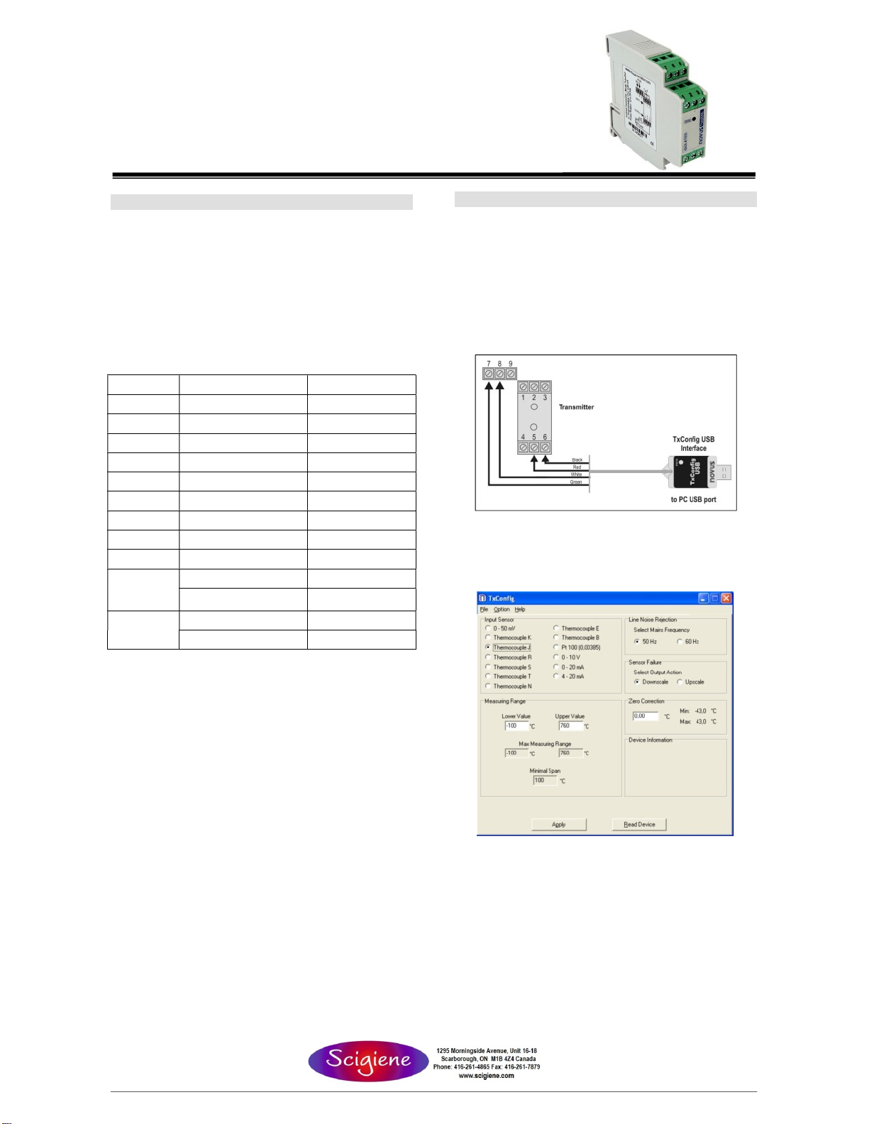
The
TxConfig
inte
r
face
connects
the
t
r
ansmitte
r
to
the
PC,
as
shown
in
Fig.
1
.
Sensor Type
Thermocouple K
Thermocouple J
Thermocouple R
Thermocouple S
Thermocouple T
Thermocouple N
Thermocouple E
Thermocouple B
Pt100
Voltage
Current
Range
-150 to 1370 °C / -238 to 2498 ºF
-100 to 760 °C / -148 to 1400 ºF
-50 to 1760 °C / -58 to 3200 ºF
-50 to 1760 °C / -58 to 3200 ºF
-160 to 400 °C / -256 to 752 ºF
-270 to 1300 °C / -454 to 2372 ºF
-90 to 720 °C / -130 to 1328 ºF
500 to 1820 °C / 932 to 3308 °F
-200 to 600 °C / -328 to 1112 ºF
0 to 50 mV
* 0 to 10 V
0 to 20 mA
4 to 20 mA
Minimum measurement span
100 °C
100 °C
400 °C
400 °C
100 °C
100 °C
100 °C
400 °C
40 °C
5 mV
1 V
2 mA
2 mA
Fig. 1 – TxConfig Interface USB connections
Once
the
connection
is
accomplished,
the
softwa
r
e
shows
the
configu
r
ation
options
of
the
t
r
ansmitte
r
model
attached.
Access
the
Help
fo
r
usage
inst
r
uctions.
The
TxConfig
sc
r
een
in
shown
in
Fig.
2
.
Table 1 – Transmitter input sensors’
Ou
t
pu
t:
2
-
wi
r
e
4
-
20
mA,
linea
r
with
r
espect
to
the
measu
r
ed
signal.
Resolu
t
ion
:
0.001
mA
(
14
bits
)
To
t
al
Accu
r
acy
:
Bette
r
than
0.3
%
of
the
maximum
span
fo
r
the
r
mocouples
and
0.2
%
fo
r
Pt100
and
voltage;
Response
Time
:
<
500
ms
Isola
t
ion
:
Between
the
senso
r
and
the
4
-
20
mA
loop
(
1000
V
/
1
min
)
.
Powe
r
Supply
:
12
to
35
Vdc,
ac
r
oss
the
t
r
ansmitte
r
;
Maximum
Load
(
RL
)
:
RL
(
max.
)
=
(
Vdc
–
12
)
/
0.02
[
Ω
]
We
r
e:
Vdc=
Powe
r
supply
voltage
Ope
r
a
t
ing
Tempe
r
a
t
u
r
e
:
-
40
to
85
°
C
Humidi
t
y
:
0
to
90
%
UR
Elec
tr
omagne
t
ic
Compa
t
ibili
t
y
:
EN
50081
-
2,
EN
50082
-
2
In
t
e
r
nal
p
r
o
t
ec
t
ion
agains
t
pola
r
i
t
y
inve
r
sion.
Cold
junc
t
ion
compensa
t
ion
f
o
r t
he
r
mocouples.
Fig. 2 – TxConfig main screen
The
fields
in
the
sc
r
een
mean:
1.
Inpu
t
Senso
r
:
Choose
the
desi
r
ed
tempe
r
atu
r
e
senso
r
among
the
available
options.
See
Table
1
.
2.
Measu
r
ing
Range
:
Defines
the
beginning
and
the
end
of
the
r
ange.
When
the
Low
Scale
Limit
is
configu
r
ed
with
a
value
highe
r
than
the
Full
Scale
Limit,
the
cu
rr
ent
output
will
have
a
dec
r
escent
behavio
r
(
20~4
mA
)
.
The
values
configu
r
ed
in
these
fields
can
not
be
beyond
the
senso
r
measu
r
ing
r
ange.
The
minimum
span
value
has
to
be
obse
r
ved
as
well
(
see
Table
01
)
.
1
/
3