manuals.online logo
Brands
  1. Home
  2. •
  3. Brands
  4. •
  5. scigiene
  6. •
  7. Transmitter
  8. •
  9. scigiene TxMiniBlock User manual

scigiene TxMiniBlock User manual

1/2
TxMiniBlock
TEMPERATURE TRANSMITTER –OPERATING MANUAL V1.0X
1INTRODUCTION
TxMiniBlock is a 4-20 mA 2-WIRE Pt100 temperature transmitter to be
assembled in heads. The desired temperature measurement range as well as
other transmitter features can be easily configured through the TxConfig
software and the TxConfig-USB interface.
The output current has a linear behavior relative to the temperature measured
by the sensor.
2SPECIFICATIONS
Sensor input: Pt100.
Maximum Range: -200 to 650 ºC
Minimum Span: 40 ºC
3-wires, Excitation of 0.20 mA, = 0.00385, according
NBR 13773.
To use 2-wires Pt100, connect together terminals 2 and
3.
Total accuracy (Tamb 25 ºC): Maximum error 0.2 % of the maximum range
for Pt100;
Response time: < 100 ms
Output: Current of 4-20 mA or 20-4 mA, 2-wires; linear relative to the
temperature measured by the sensor.
Output resolution: 0.004 mA (12 bit)
Power supply: 12 to 35 Vdc across the transmitter
Maximum load (RL): RL (max.) = (Vdc –12) / 0.02 []
Where: Vdc= Power supply voltage (12 to 35 Vdc)
Operating temperature: -40 to 50 °C
Humidity: 0 to 90 % RH
Calibration thermal drift: ± 40 ppm / °C full range
Electromagnetic compatibility: EN 50081-2, EN 50082-2
No electrical isolation between the sensor and the 4-20 mA loop.
Internal protection against supply voltage polarity inversion.
Housing in ABS, 34 mm diameter and maximum height of 18 mm.
3CONFIGURATION
If the Pt100 sensor is already configured, no intervention is necessary;
installation can be immediately performed. When a configuration change is
required, it can be made with the TxConfig software; it is then sent to the
transmitter using the TxConfig Interface.
The TxConfig interface has a complex electronic circuit. Do
not use any other interface or cable connection to USB; the
product will be damaged and this damage is not covered
under warranty.
TxConfig interface and software are comprised in the Transmitter Setup Kit that
can be purchased from the manufacturer or from authorized dealers. The
software can be upgraded for free at the manufacturer’s website. To install, run
Tx_setup.exe and follow the instructions.
The interface connects the transmitter to the computer, as show in Figure 01.
Figure 01 –TxConfig USB Interface connections
During setup, the transmitter must be powered electrically. The TxConfig
interface itself supplies the power, but this depends on the computer used.
Another way is to run the setup with the transmitter connected to this process,
using the energy from the same source that feeds this process (loop). See
Figure 02.
Figure 02 –TxConfig Interface connections –Loop powered
After the connections are made, the user must run the TxConfig software
and, if necessary, use the Help topic to configure the transmitter.
Figure 03 shows the main screen of the TxConfig software.
Figure 03 –Main screen of the TxConfig software
The fields in this screen have the following purposes:
1. Input Sensor: Pt100 (0.00385).
2. Measurement Range: Defines the transmitter measurement range.
Lower range limit corresponds to the desired temperature for a current of
4 mA.
Upper range limit corresponds to the desired temperature for a current of
20 mA.
When the Lower Limit is set with a value higher than the Upper Limit value, the
output current operates between 20 and 4 mA.
The chosen values cannot exceed the Sensor Range shown in this field
and cannot establish a band with width (span) lower than the Minimum
Range value indicated below in this field. See table below.
Type of Sensor
Maximum
Measurement Range
Minimum
Measurement Range
TxMiniBlock Transmitter
2/2
Pt100
-200 a 650 °C
40 °C
Table 01 –Transmitter input sensor
3. Filtration Optimization: Filters the measurements made by the
transmitter eliminating interferences from the electrical system that feeds
the process.
4. Sensor Failure: Establishes the behavior of the output when problems are
presented by the sensor. When Minimum is selected, the output current shifts to
< 4 mA (down-scale), typically used in refrigeration. When Maximum is selected,
if shifts to > 20 mA (up-scale), typically used for heating.
5. Zero Correction: Corrects minor errors presented by the transmitter, for
example, when the sensor is changed. See item Operation in this manual.
6. Transmitter Information: In this field, there are data that identify the
transmitter. This information must be informed in any consultation with the
manufacturer.
7. Read Configuration: When pressed, this allows one to read the
configuration on the transmitter connected.
8. Send Configuration: When pressed, this allows one to send the
configuration to the transmitter connected.
Note: If, on the purchase order, the user does not define a specific
configuration, the following configuration will be set:
•Pt100 sensor, range 0 to 100 °C, 0 °C zero correction.
•Filter to 60 Hz and maximum output for sensor failures.
4MECHANICAL INSTALLATION
The TxMiniBlock transmitter is suitable to be installed on heads.
Figure 04 –Transmitter dimensions
5ELECTRICAL INSTALLATION
Polyamide housing for the terminals.
Section of the wire: 0.14 a 1.0 mm².
Recommended Torque: 0.8 Nm.
RECOMMENDATIONS FOR INSTALLATION
•Input signal conductors should run away from power and contactor wires,
if possible, in grounded conduits.
•The instruments must be powered by a suitable network for
instrumentation.
•System failure should always be taken into account when designing a
system to avoid irreversible damage to equipment or people. Installing
RC filters (47 and 100 nF, in series) is strongly recommended at
contactor coils or any other inductors.
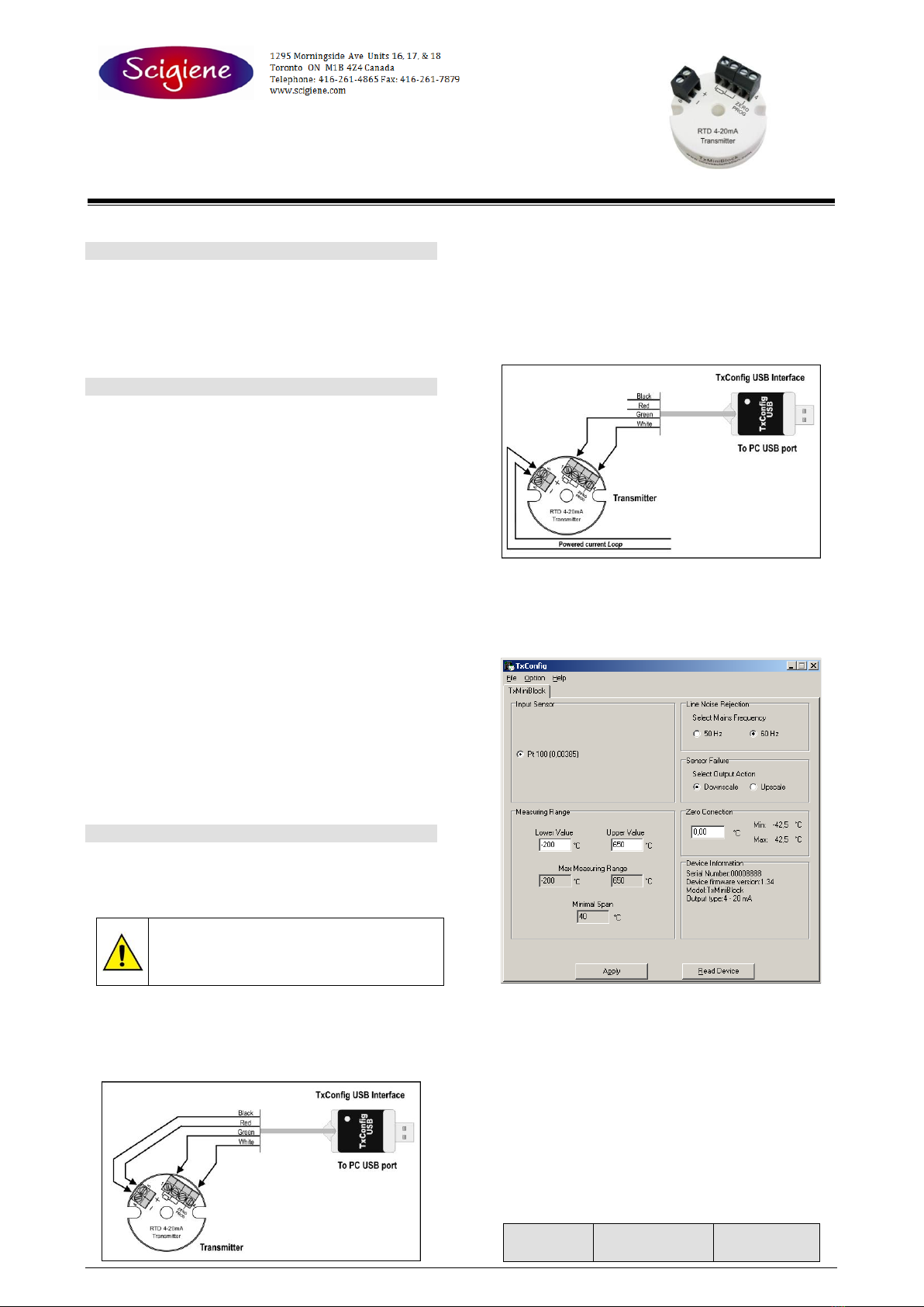
ELECTRICAL CONNECTIONS
Figure 05 below shows the transmitter wiring. Terminals 1, 2 and 3 are used
for sensor input. For 2-wire Pt100, terminals 2 and 3 shall be connected
together. The LOAD represents the input shunt of an instrument measuring
the 4-20 mA current loop.
The figure below shows the electrical connections required. Terminals 1, 2 and
3 are used for the Pt100 input. For 2-wire Pt100, terminals 2 and 3 must be
interconnected.
Figure 05 –Transmitter electrical connections –Pt100
The LOAD represents the input shunt of an instrument measuring the 4-20
mA current loop (indicator, controller, recorder, etc).
6OPERATION
The sensor input is factory calibrated. Recalibration in the field is not
recommended, but it can be accomplished through the TxConfig software.
Contact the factory for the calibration procedure.
When necessary, fine adjustments to the transmitter output current can be
accomplished directly at the transmitter. To do so, short circuit transmitter
terminals 1and 4. After 2seconds, the output current starts to increase
gradually until it reaches 0.8 mA above the initial value. After reaching that
value, it drops to 0.8 mA below the initial value, increasing gradually again.
The user must monitor the output current and open the circuit when the current
reaches the desired value.
The offset correction can also be accomplished through the TxConfig
software. The TxConfig interface can be connected to the transmitter while it
is operating in the process. See in Figure 03 the Zero Correction field in the
main screen of the TxConfig software.
The user must choose the sensor span most suitable to the application. The
maximum and minimum sensor spans are limited in the TxMiniBlock and in
the TxConfig software. The user can configure any value within those two
limits.
It is important to note that the accuracy of the transmitter is always based on
the maximum range of the Pt100 sensor, regardless of the configured span. .
Example:
•Pt100 maximum span = 850 °C; 0.2% accuracy.
•Maximum error = 1.7 °C (0.2 % de 850 °C)
The error is the same no matter if total span is used (-200 to 650 °C) or a
narrower user-defined span is used, like 0 to 100 °C.
Note: When using a Pt100 simulator, make sure the TxMiniBlock’s Pt100
excitation current (0.20 mA) is compatible with the simulator specification.
7SAFETY INFORMATION
Any control system design should take into account that any part of the system
has the potential to fail. This product is not a protection or safety device and
its alarms are not intended to protect against product failures. Independent
safety devices should be always provided if personnel or property are at risk.
Product performance and specifications may be affected by its environment
and installation. It’s user’s responsibility to assure proper grounding, shielding,
cable routing and electrical noise filtering, in accordance with local regulations,
EMC standards and good installation practices.
8SUPPORT AND MAINTENANCE
This product contains no serviceable parts inside. Contact our local distributor
in case you need authorized service.
9LIMITED WARRANTY AND LIMITATION OF LIABILITY
NOVUS warrants to the original purchaser that this product is free from defects
in material and workmanship under normal use and service within one (1) year
from the date of shipment from factory or from its official sales channel to the
original purchaser.
NOVUS liability under this warranty shall not in any case exceed the cost of
correcting defects in the product or of supplying replacement product as herein
provided and upon the expiration of the warranty period all such liability shall
terminate.
For complete information on warranty and liability limitations, check
appropriate section in our web site

Other scigiene Transmitter manuals

scigiene TxBlock User manual

scigiene

scigiene TxBlock User manual

scigiene TxIsoRail User manual

scigiene

scigiene TxIsoRail User manual

Popular Transmitter manuals by other brands

Phonak Roger Covert user guide

Phonak

Phonak Roger Covert user guide

Evikon E2615-LEL user manual

Evikon

Evikon E2615-LEL user manual

Crestron DM-TX-4KZ-202-C Do guide

Crestron

Crestron DM-TX-4KZ-202-C Do guide

PR electronics PRetop 5334 manual

PR electronics

PR electronics PRetop 5334 manual

Crestron HD-TXA-4KZ-101 Getting started

Crestron

Crestron HD-TXA-4KZ-101 Getting started

Audiovox 128-5971 Installation sheet

Audiovox

Audiovox 128-5971 Installation sheet

Yongnuo ST-E2 user manual

Yongnuo

Yongnuo ST-E2 user manual

Sony WLL-CA50 Maintenance manual

Sony

Sony WLL-CA50 Maintenance manual

FISCHER DE23 Series operating manual

FISCHER

FISCHER DE23 Series operating manual

EYC FTS34 Operation manual

EYC

EYC FTS34 Operation manual

GESTRA LRG 16-4 Installation instructions manual

GESTRA

GESTRA LRG 16-4 Installation instructions manual

Extron electronics XTP T VGA user guide

Extron electronics

Extron electronics XTP T VGA user guide

Horizon Hobby REVOLUTION RVOF1106 manual

Horizon Hobby

Horizon Hobby REVOLUTION RVOF1106 manual

EMERGENCY BEACON CORPORATION EBC-406HM Instruction and maintenance manual

EMERGENCY BEACON CORPORATION

EMERGENCY BEACON CORPORATION EBC-406HM Instruction and maintenance manual

Sony DWZ-B50I quick start guide

Sony

Sony DWZ-B50I quick start guide

Hides HV-100E Quick installation guide

Hides

Hides HV-100E Quick installation guide

JUMO ecoTRANS Lf 01 operating instructions

JUMO

JUMO ecoTRANS Lf 01 operating instructions

Lectrosonics MM400 operating instructions

Lectrosonics

Lectrosonics MM400 operating instructions

manuals.online logo
manuals.online logoBrands
  • About & Mission
  • Contact us
  • Privacy Policy
  • Terms and Conditions

Copyright 2025 Manuals.Online. All Rights Reserved.