manuals.online logo
Brands
  1. Home
  2. •
  3. Brands
  4. •
  5. BAPI
  6. •
  7. Transmitter
  8. •
  9. BAPI Delta Style User manual

BAPI Delta Style User manual

Installation and Operating Instructions
Delta Style Room Humidity Transmitter with Optional Temp. Sensor
BA/#-Hxxx-R
Building Automation Products, Inc., 750 North Royal Avenue, Gays Mills, WI 54631 USA
Tel:+1-608-735-4800 • Fax+1-608-735-4804 • E-mail:[email protected] • Web:www.bapihvac.com
Specications subject to change without notice.
27417_ins_Delta_RH
1 of 4
rev. 04/15/14
LOCATION: Avoid mounting on outside walls or in direct sunlight.
JUNCTION BOX (J-Box), (Fig. 3)
1. Pull the wire through the wall and out of the junction box, leaving about
six inches free.
2. Pull the wire through the hole in the base plate.
3. Stuff insulation into box behind the sensor plate and screw the plate
rmly to the J-box.
4. Secure the back plate to the box using the #6-32 x 5/8 inch mounting
screws provided.
5. Terminate the unit according to the guidelines in the Termination section.
6. Attach cover by latching it to the top of the base, rotating the cover down
and snapping it into place.
7. Secure the cover by backing out the lock-down screws using a 1/16”
Allen wrench until it is ush with the bottom of the cover.
DRYWALL MOUNTING (Similar to Fig. 3 but without the J-Box)
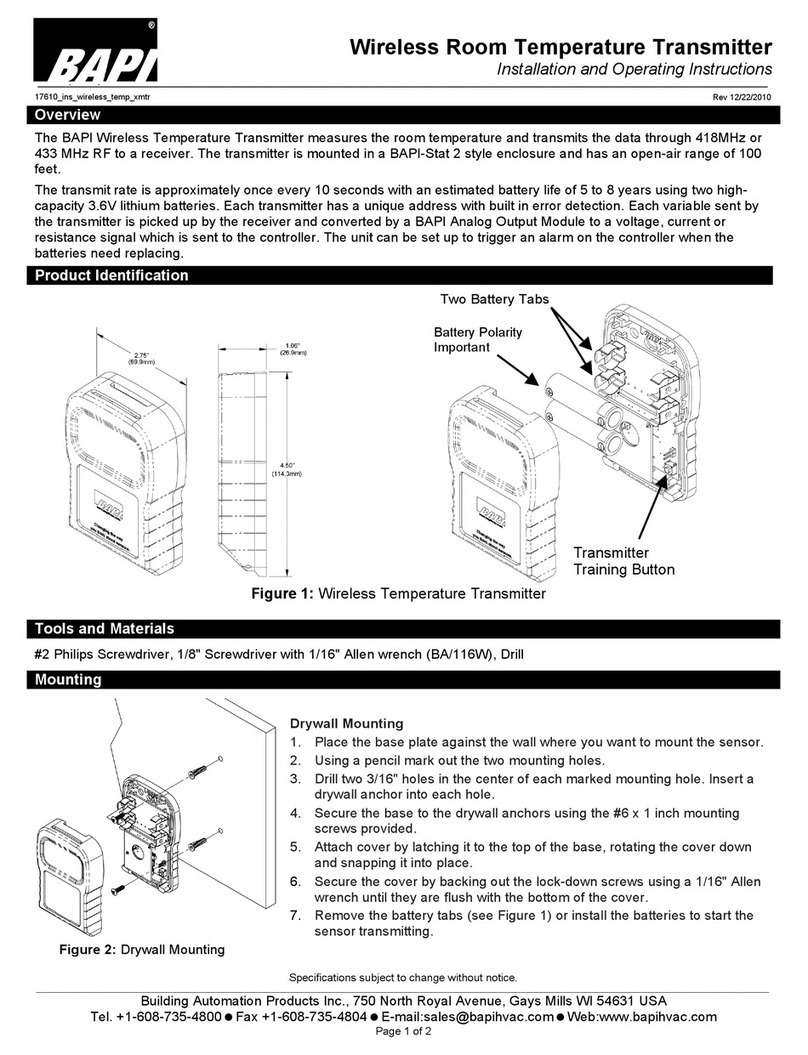
1. Place the base plate against the wall where you want to mount the
sensor and mark the two mounting holes and the area where the wires
will come through the wall.
2. Drill two 3/16” holes in the center of each marked mounting hole. Insert a
drywall anchor into each hole.
3. Drill one 1/2” hole in the middle of the marked wiring through hole area.
4. Pull the wire through the wall and out the 1/2” hole, leaving about six inches free.
5. Pull the wire through the hole in the base plate.
6. Stuff insulation into the wall behind the sensor plate and screw the plate rmly to the wall anchors.
7. Secure the base to the drywall anchors using the #6 x 1” mounting screws provided.
8. Terminate the unit according to the guidelines in the Termination section.
9. Attach cover by latching it to the top of the base, rotating the cover down and snapping it into place.
10. Secure the cover by backing out the lock-down screws using a 1/16” Allen wrench until it is ush with the sides of the
cover.
Note: In any wall-mount application, the wall temperature and the temperature of the air within the wall cavity can cause
erroneous readings. The mixing of room air and air from within the wall cavity can lead to condensation, erroneous
readings and sensor failure. To prevent these conditions, BAPI recommends sealing the conduit leading to the
junction box with berglass insulation.
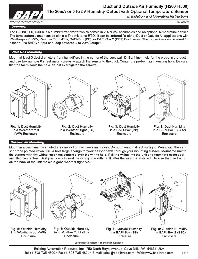
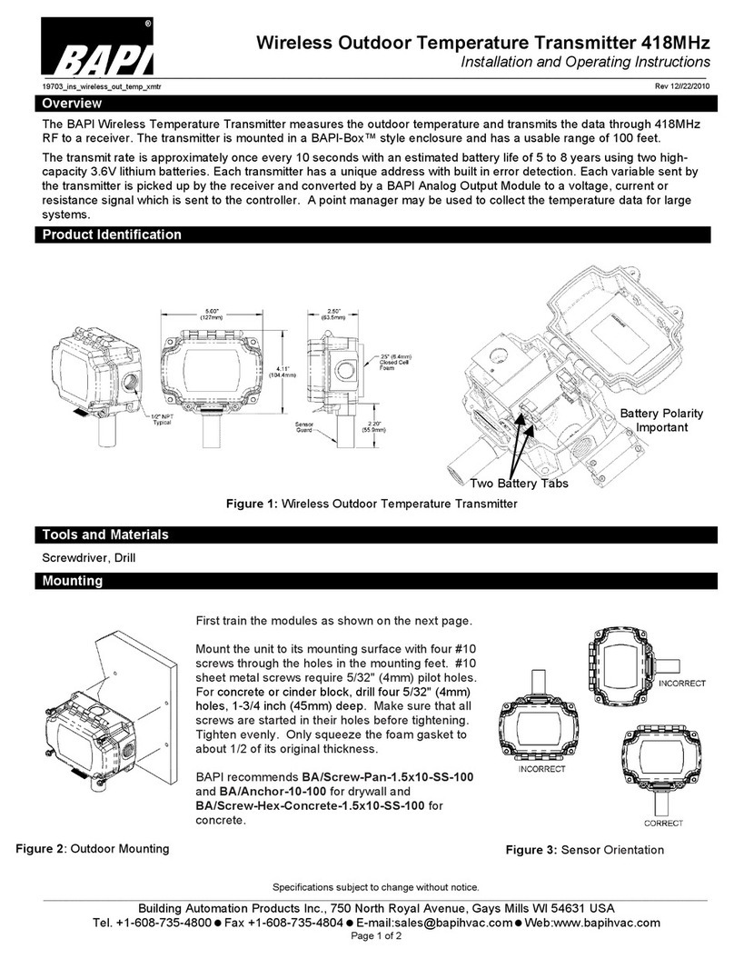
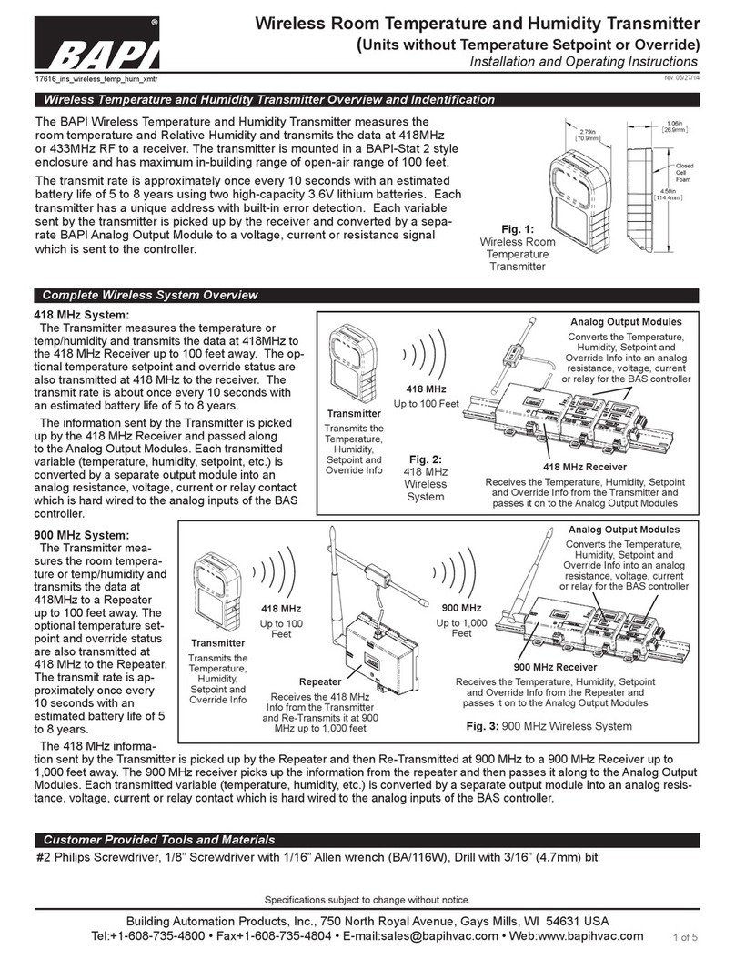
The Delta Style room humidity transmitter
measures relative humidity (RH) and outputs a
0 to 100% RH on either a 4 to 20mA, 0 to 5V or
0 to 10V signal. It can be ordered with optional
temperature sensor and LCD display. The unit is
powered by a wide selection of AC or DC power
depending on the signal selection. The optional
LCD display can selectively show RH and/or
temperature values. The optional temperature
sensor can use any 2-wire passive sensor.
Overview and Indentication
Fig. 1: Delta Style Room
Humidity Transmitter without
Display
Fig. 2: Delta Style Room
Humidity Transmitter with
Display
Fig. 3: Delta Style Unit Installation.
Mounting hardware is provided for both
junction box and drywall installation
(junction box installation shown).
Mounting
Installation and Operating Instructions
Delta Style Room Humidity Transmitter with Optional Temp. Sensor
BA/#-Hxxx-R
Building Automation Products, Inc., 750 North Royal Avenue, Gays Mills, WI 54631 USA
Tel:+1-608-735-4800 • Fax+1-608-735-4804 • E-mail:[email protected] • Web:www.bapihvac.com
27417_ins_Delta_RH
2 of 4
rev. 04/15/14
BAPI recommends using twisted pair of at least 22AWG and sealant lled connectors for all wire connections. Larger gauge wire
may be required for long runs. All wiring must comply with the National Electric Code (NEC) and local codes. Do NOT run this
device’s wiring in the same conduit as AC power wiring.
BAPI’s tests show that uctuating and inaccurate signal levels are possible when AC power wiring is present in the same conduit
as the signal lines. BAPI does not recommend wiring the sensor with power applied as accidental arcing may damage the
product and will void the warranty.
Fig. 4: Circuit Board (shown with
optional temperature sensor)
4 to 20mA Humidity Output Termination
TERMINAL LEGEND FUNCTION
GND .................................... 4 to 20mA Loop Humidity Signal (To analog input of controller)
V+ ....................................... Main DC Power (See power requirements in specications)
V OUT ................................. Not Used (No termination)
TEMP +............................... Optional Passive Temp. Sensor (No polarity for RTDs or Thermistors)
(“+” terminal is the 5 to 30 VDC bias voltage for Semiconductors)
TEMP - ............................... Optional Passive Temp. Sensor (No polarity for RTDs or Thermistors)
(“-” terminal is the temperature signal for Semiconductors)
0 to 5VDC or 0 to 10VDC Humidity Output Termination
TERMINAL LEGEND FUNCTION
GND .................................... Ground for Power and Reference for the Humidity Voltage signal
V+ ....................................... Main Power (See power requirements in specications)
V OUT ................................. Humidity Voltage Signal Output (0 to 5VDC or 0 to 10 VDC)
TEMP +............................... Optional Passive Temp. Sensor (No polarity for RTDs or Thermistors)
(“+” terminal is the 5 to 30 VDC bias voltage for Semiconductors)
TEMP - ............................... Optional Passive Temp. Sensor (No polarity for RTDs or Thermistors)
(“-” terminal is the temperature signal for Semiconductors)
Notes: 1. Transmitter is common ground (CG) for voltage outputs
2. “TEMP +” and “TEMP -” terminals are isolated to only the temperature sensor.
Termination
Optional Communication Jack Wiring
C35 Comm.
Jack on
Delta Style
Unit Base
(Front View)
Fig. 5: C35 Comm Jack
(3.5mm plug shown for clarity)
C35 Comm.
Jack on
Delta Style
Unit Base
(Back View)
Norm: The sensor will operate normally
High: Sets the sensor value to the HIGH
temperature (see table at right)
Low: Sets the sensor value to the LOW
temperature (see table at right)
Sensor Type Low Temp (40° F) High Temp (105° F)
Resistance Value Resistance Value
1000Ω RTD 1.02KΩ (41.2°F) 1.15KΩ (101.5°F)
3000Ω Thermistor 7.87KΩ (39.5°F) 1.5KΩ (106.8°F)
10K-2 Thermistor 30.1KΩ (39.2°F) 4.75KΩ (105.8°F)
10K-3 Thermistor 26.7KΩ (35.9°F) 5.11KΩ (108.4°F)
10K-3(11K) Thermistor 7.32KΩ (43.7°F) 3.65KΩ (105.2°F)
Optional Test and Balance Switch (SW1) Operation
T&B Switch (SW1) Position and Sensor Output
BAPI does not recommend wiring the sensor with power applied as accidental arcing may damage the product
and will void the warranty.
Installation and Operating Instructions
Delta Style Room Humidity Transmitter with Optional Temp. Sensor
BA/#-Hxxx-R
Building Automation Products, Inc., 750 North Royal Avenue, Gays Mills, WI 54631 USA
Tel:+1-608-735-4800 • Fax+1-608-735-4804 • E-mail:[email protected] • Web:www.bapihvac.com
Specications subject to change without notice.
27417_ins_Delta_RH
3 of 4
rev. 04/15/14
10 Second Toggle Humidity Display Only
Temp. Display Only
J2 Jumper “On”
Degrees = °F
°F or °C Indication (for display units only)
The jumper on J2 determines whether the unit will
display in Fahrenheit or Celcius. With the jumper
“On”, the unit displays in Fahrenheit which is the
factory default. (See diagrams at right.)
J2 Jumper “Off”
Degrees = °C
Humidity Reading Offset (for display units only)
The Humidity reading can be offset by ±5% by turning
POT R20. (See diagram at right.)
Zero Humidity Offset (centered) is the factory
default. Turning clockwise increases the Humidity
Offset by up to +5%. Turning counterclockwise
decreases the Humidity Offset by up to -5%.
Unit Interval Toggle Rate Between Display of Temperature and Humidity (for display units only)
POT R6 sets the approximate toggle rate between
temperature and humidity display of 3 to 15 seconds. POT
R6 can also be used to set a constant display of either
temperature or humidity. (See diagram at right.)
Specications
Power: Reverse polarity protected.
4 to 20 mA Output ........ 10 to 35 VDC, 22mA max
0 to 5 VDC Output ........ 10 to 35 VDC, 22mA max
12 to 24 VAC, 0.53VA max
0 to 10 VDC Output) ..... 15 to 40 VDC, 6mA max
15 to 28 VAC, 0.14VA max
Note: half wave DC power is recommended. If AC power is
used, it must be shielded from the signal wiring.
Sensor:
Humidity ............. Capacitive w/ temperature compensation
& digital output.
%RH resolution is 8 bit
Optional Temp. ... Passive Thermistor, RTD or
Semiconductor with bias of 5 to 30VDC
Filter: None
RH Accuracy: RH Sensor chip
200 ±2%, from 20% to 80%RH @77ºF
200 ±3%, from <20% to >80%RH @77ºF
300 ±3%, from 0% to 100%RH @77ºF
Resolution RH sensor 0.4%
Temp Display Accuracy: Temperature Chip only
Temperature ±0.6˚C @25˚C
Resolution Temp sensor 0.2˚
Optional Temp Sensor Accuracy: Passive 2 wire only
Thermistor* ......... (std) ±0.36ºF, (±0.2ºC)
(High) ±0.18ºF, (±0.1ºC), [XP] option
RTD ................... Platinum (PT), 3.85Ω/ºC for 1KΩ RTD
Platinum (PT), 0.385Ω/ºC for 100Ω RTD
Nickel (Ni), 2.95Ω/ºF for the JCI RTD
Solid State .......... AD592, bias 5-30VDC
Output: Updated every 2 seconds
RH (0 to 100%) 4 to 20mA, 0 to 5VDC or 0 to 10VDC
Temperature Passive Resistance or Semiconductor
Impedance:
Current 700Ω @ 24VDC minimum
Voltage 10KΩ maximum
Terminals: Cage clamp, 16 to 22 AWG
Wiring: 2 to 6 pair depending on options
Mounting:
Standard 2”x4” J-box or drywall, screws provided
Field Humidity Calibration Offset: (Factory calibrated)
%RH Adj. Potentiometer, ±5%
Enclosure Material: ABS Plastic, UL94V-HB
Optional Display: 3.5 digit LCD
Dimensions ......... 0.5”H x 1.1”W, Digits .4”H
(13.34 x 29.21mm), (Digits 10.29mm H)
Range ................ 0 to 100%, -58 to 199.5˚F (-50 to 150˚C),
factory set
Span ................... 0 to 100%, 32 to 122˚F (0 to 50˚C), factory set
Resolution .......... 0.5%RH or 0.5˚F or °C
Units ................... ˚F or ˚C, Board jumper (J2)
Update ................ Every 2 seconds, factory set
Alternating .......... Temp/RH, adjustable 3-15 seconds or xed
temperature or humidity
Power up ............ 0% RH & 0.0˚ at power up for OK
Then reads value after 2 seconds
Fault ...................
RH 100% or Temp 0% for sensor fault after 500 sec.
Optional Comm. Jack:
-C35 3.5mm Phono jack
Optional Test & Balance Switch:
-TB 3 position switch High/Normal/Low
Passive temp sensor output only
Environmental Ambient Range:
Temp 32º to 122ºF, (0º to 50ºC)
Humidity 5% to 95% RH (Non-Condensing)
Agency: RoHS, UL94V-HB,
CE* (EN50081-1:1998, EN61000-6-2)
*All passive thermistors 10KΩ and smaller
are CE Compliant
Installation and Operating Instructions
Delta Style Room Humidity Transmitter with Optional Temp. Sensor
BA/#-Hxxx-R
Building Automation Products, Inc., 750 North Royal Avenue, Gays Mills, WI 54631 USA
Tel:+1-608-735-4800 • Fax+1-608-735-4804 • E-mail:[email protected] • Web:www.bapihvac.com
Specications subject to change without notice.
27417_ins_Delta_RH
4 of 4
rev. 04/15/14
1 Mount and wire the transmitter per the instructions above (Mounting and Termination)
2 Read the optional passive sensor value at the controller. It should show the room temperature per the accuracy spec above.
3 Test and Balance option is described in the “Conguration Adjustments” above and will only affect the optional passive tem-
perature sensor [TEMP +] and [TEMP -] output. As you switch from High to Low and to Norm you should see the resistance
change per the table in section “Optional Test & Balance Switch”.
4 If the controller is not hooked up or power has not been applied yet, disconnect the [TEMP +] wire and measure the [TEMP
+] terminal and [TEMP –] terminal with an Ohm meter for a thermistor or an RTD. A solid state sensor must be read from a
controller. The resistance should correlate with the temperature in the room. Resistances to temperature charts are available
on line at BAPI web site “BAPIHVAC.com”. Reconnect the [TEMP +] wire when nished.
5 Power up the transmitter and read the output values after 2 seconds, per the instructions below.
• Voltage Output: Read the voltage output with a volt meter from [GND] to [V OUT]. Read the RH voltage in proportion to
the RH sensor. See the Humidity Formula chart below.
• Current Output; Read the current output with a current meter in series with the [GND] terminal and eld wire. Read the
RH current (between 4-20mA) in proportion to the RH sensor. See the Humidity Formula chart below.
6 If this is a display transmitter then follow the “Conguration Adjustments” to set the °F or
°C indication and unit interval toggle rate.
• °F or °C Indication: Set the display units to ˚F or ˚C as needed with J2 jumper
• Unit Interval Toggle Rate: Set the temp. and humidity display rotation with R6.
Problems:
General Troubleshooting
Incorrect Humidity
Incorrect Temperature
Faulty %RH/Temperature
Sensor Chip
Commissioning
Diagnostics
Possible Solutions:
• Determine that the input is set up correctly in the controller and building automation software.
• Check wiring at the sensor and controller for proper connections.
• Check for corrosion at either the controller or the sensor. Clean off the corrosion, re-strip the
interconnecting wire and reapply the connection. In extreme cases, replace the controller,
interconnecting wire and/or sensor.
• Label the interconnecting sensor wires then disconnect them at the sensor end and controller end.
With the wires disconnected at both ends, measure the resistance from wire-to-wire with a multi-
meter. The meter should read greater than 10 Meg-ohms, open or OL depending on the meter.
Now short the interconnecting wires at one end. Go to the other end and measure the resistance
from wire-to-wire with a multi-meter. The meter should read less than 10 ohms (22 gauge or larger,
250 feet or less). If either test fails, replace the wire.
• Check power supply/controller voltage supply.
• Disconnect sensor and check power wires for proper voltage (see specications).
• Check all controller software parameters (V/I/Ω).
• If available, check the sensor against a calibrated instrument such as a hygrometer.
• Determine if the sensor is exposed to an external environment different from the room (conduit
draft, diffuser above, radiation below, etc.).
• Adjust the offset POT R20 to your reference value (±5%). (See “Humidity Reading Offset” section)
• Determine that the sensor’s wires are properly connected to the correct controller input terminals.
• Check the wires at the sensor and controller for proper connections.
• Measure the physical temperature at the temperature sensor’s location using an accurate
temperature standard. Output to Controller; Disconnect the temperature sensor’s wire terminals
[TEMP+] & [TEMP-] and measure the temperature sensor’s resistance across the sensor
output pins with an ohmmeter. Compare the temperature sensor’s resistance to the appropriate
temperature sensor table on the BAPI web site (BAPIHVAC.com). If the measured resistance is
different from the temperature table by more than 5% call BAPI technical support.
• Determine if the sensor is exposed to an external environment different from the room (conduit
draft, diffuser above, radiation below)
• On power up, a normally-operating unit will display 0%RH and 0.0 ˚F or °C for 2 seconds. After
2 seconds, the unit will begin to display the actual %RH and temperature. If there is no display
reading after 500 seconds (0%RH and 0.0°F or °C), then the unit will default to a %RH reading of
100% and a temp reading of 0.0°, indicating a bad sensor. Replace the unit.
Output Humidity Formula
4 to 20mA %RH =(mA-4)/0.16
0 to 5VDC %RH = V/0.05
0 to 10VDC %RH = V/0.1
2 to 10VDC %RH = (V-2)/0.08

Other BAPI Transmitter manuals

BAPI 418MHz User manual

BAPI

BAPI 418MHz User manual

BAPI BA/T100 Manual

BAPI

BAPI BA/T100 Manual

BAPI Wireless Room Temperature Transmitter User manual

BAPI

BAPI Wireless Room Temperature Transmitter User manual

BAPI BAPI-Stat Quantum Slim Owner's manual

BAPI

BAPI BAPI-Stat Quantum Slim Owner's manual

BAPI H200 User manual

BAPI

BAPI H200 User manual

BAPI Wireless Room Temperature and Humidity... User manual

BAPI

BAPI Wireless Room Temperature and Humidity... User manual

Popular Transmitter manuals by other brands

RKI Instruments 65-2424RK Operator's manual

RKI Instruments

RKI Instruments 65-2424RK Operator's manual

PNI Valentine F800 user manual

PNI

PNI Valentine F800 user manual

IEI Technology Reporter PIR-300 manual

IEI Technology

IEI Technology Reporter PIR-300 manual

GEIGER Remote AIR GF2900 Original assembly and operating instructions

GEIGER

GEIGER Remote AIR GF2900 Original assembly and operating instructions

Mighty Module MM4431 manual

Mighty Module

Mighty Module MM4431 manual

Emerson Rosemount 644 Reference manual

Emerson

Emerson Rosemount 644 Reference manual

Evikon PluraSens E2670-O2 user manual

Evikon

Evikon PluraSens E2670-O2 user manual

dymax BlueWave MX-275 user guide

dymax

dymax BlueWave MX-275 user guide

EDOBE XDOM IMRF user guide

EDOBE

EDOBE XDOM IMRF user guide

Ramsey Electronics FM25B Assembly and instruction manual

Ramsey Electronics

Ramsey Electronics FM25B Assembly and instruction manual

Lightware UMX-TPS-TX120 quick start guide

Lightware

Lightware UMX-TPS-TX120 quick start guide

Vaisala CARBOCAP GMT220 SERIES user guide

Vaisala

Vaisala CARBOCAP GMT220 SERIES user guide

BD Sensors DMK 457 operating manual

BD Sensors

BD Sensors DMK 457 operating manual

Lectronics DCHT quick start guide

Lectronics

Lectronics DCHT quick start guide

Sony DWT-P01N operating instructions

Sony

Sony DWT-P01N operating instructions

William Sound WIR TX-9 DC Installation guide & user manual

William Sound

William Sound WIR TX-9 DC Installation guide & user manual

HETRONIC NOVA XL quick start guide

HETRONIC

HETRONIC NOVA XL quick start guide

CETEC Sparta 625A Technical manual

CETEC

CETEC Sparta 625A Technical manual

manuals.online logo
manuals.online logoBrands
  • About & Mission
  • Contact us
  • Privacy Policy
  • Terms and Conditions

Copyright 2025 Manuals.Online. All Rights Reserved.