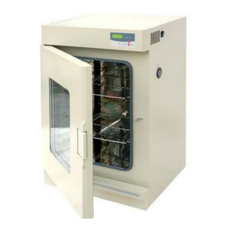
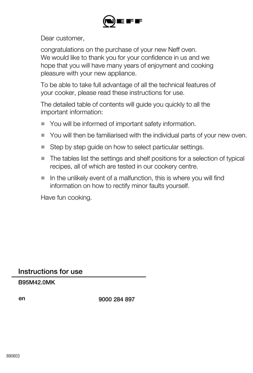
SciQuip Oven-S Series User manual

This Manual applies to:
Please read thisGuide attentively beforeusing and be
careful of keepingthe Manual incase of contingentuse.
User's Manual
Oven-S Series
Blast Air Oven

1.Grounding outlet to avoid accidental electric shock or fire disaster.
2.Do not attempt to repair the product yourself. Do not open th e power box indiscriminately to
avoid electric shock.
3.Please an the independent mains jack socket. Make sure the proper plug with outlet. Loose
connection will result in overheating, electric shock, or even fire disaster.
4.Do not pull out the plug when it is operating. Do not drag the wire to plug the outlet.
5.Do not damage the wires or use the undesignated wires. Do not try to extend the wires or attach
wires at the middle by yourself. Improper handling of wires will result in fire or electric shock.
6.Plug the outlet with wet will get risk of electric shock.
7.Do not put fingers, rods or other kinds of foreign bodies into the inlet or outlet of air.
8.In case of malfunction or burning smell, the unit must be immediately unplug and ceased for
further checking, or use a circuit breaker to cut off the power supply. Continuance of abnormal state
will result in fire caused by overheating.
9.The electric power supply must be cut off under following situations:
9.1.When opening the door of power box. Without cutting off power supply, the opening of the door
will probably result in electric shock.
9.2.When replacing the fuse. Replacing the fuse without cutting off the power supply will probably
result in electric shock.
9.3.When the malfunction occurs. Mishandling will result in the further damage of the equipment or
accidental injury.
9.4.When not using for a long period of time. The dust accumulated on the outlet may leads to fire
cause by electric leakage.
9.5.When moving the equipment. Moving the equipment connected with power supply will
probably result in electric shock.
Danger! (Warnings against likely injury or death.)
Please be sure to follow the instructions, which are
really important for your safety.
Safety instruction!
1.The unit must be placed horizontally on solid, flat floors.
2.The unit must be provided with sufficient clearance on all sides of the unit, at least 20cm.
3.Do not leave the unit in a location exposed to direct sunlight or near heater.
4.The unit must be kept faraway from source of electromagnetic interference.
5.When in normal operation, culture inside the incubator should be placed to the extent of which
the air flow inside the equipment is not affected to keep the temperature uniformity in the working
chamber.
6.Make sure the shelves inside the chamber is placed horizontally.
7.Open or close the door heavily will probably leads to the damage of the equipment.
8.When in operation, do not open the door indiscriminately which will affect the temperature
inside.
9.The exterior of equipment must be kept away from volatile, flammable, explosive liquids or
gases.10.Please keep the chamber clean. Regular cleaning is required.
Instructions to keep the normal life and proper
operations of the equipment!
Apart from the above warnings and instruction, there are
several other special reminder with a exclamation point
within a triangle, please read and follow. Any neglect will
probably lead to hidden trouble, serious damage, or
accidental injury.
Attention!
Attention!
Attention
Please close the door immediately after take/put the sample,otherwise the
temperature control precision could the affected.
If the door had to be opened for a long time, please power off the unit.

1.Key features
2.Technical Specifications
3.Control Panel
4.Preparation and Start-up
5.Switch between operating modes
6.
Settings for Program control mode
8.Setting and Application of other functions
.Operation and Switch off
10.Electric theorem
11.Normal Malfunction and Debugging
Setting of parameter under the
constant temperature control mode
7.
9
7.
8.Setting and Application of other functions
Table of contents
1.Key features
1.Individualized 10 segments, 18-step preset programmes achieve temperature preset timing
programs or reciprocating, stepped, ladderlike temperature running.
2.Sound heat insulation design and the transparent glass door meet European security
standard.
3.Automatic poweron and poweroff, timing operation, clock indicating, poweroff recovery,
parameter recalling and encryption, temperature indicating and correcting, RS-232 interface
and built-in microprinter.
4.Monitoring timer, independent exceeding guard, over temperature protector(adjustable).
5.Independent protector for electric leakage and over current.
6.Self-diagnosed techniques, such as power cut alarm, sensor failure alarm, and upper and
lower temperature limit exceeding alarm.
7.Highly responsive thermal sensor and environmental scanning microprocessor chip.
8.Three-dimensional heating technology ensures the solid temperature uniformity in the
working chamber.
9.Sound airway structure and gentle airflow circulation design.
10Unique design of chamber guaranties the cleanliness of the sample.
11.Mirror stainless steel chamber, electro polished stainless steel shelves and toughened
glass internal door.
12.The luxurious and elegant profile with aesthetic designing.
1

2.Technical Specifications
Oven-55s
Oven-30S
Oven-110S
Oven-210S
Oven series (Heater is on the back of the chamber, horizontal air-flow)
2
Illustration of ControlPanel
3.Control Panel
3
2.For Oven-210S
LCD Display
TM
COLD
Increase button
Decrease button
Temperature button
Print button
SET
button
Time
button
Graphic chart display button
Temperature exceeding alarm indicator
Heating indicator
Actual Temperature indicator
Time indicator
Operating status indicator
Setted Temperature Indicator
Status keeping indicator
Refrigeration indicator
Operating button
R/H/SR/H/S SETSET
COLD
HOLD
RUN
PV
SV
TM
Status keeping indicator
Operating status indicator
Actual Temperature indicator
Setted Temperature Indicator
Refrigeration
indicator
Time indicator
LCD Display Heating indicator
Temperature exceeding alarm indicator
Graphic chart display button
Temperature button
Decrease button
Print button
Decrease button
SET button
Operating button
Time button

Refrigeration indicator:
When the refrigerating system is working, this indicator will be on.
SET button:
Press this button to change the parameter
Increase button:
Press this button, the parameter will increase by one digit, the parameter will keep increasing while this button is held on.
Decrease button:
Press this button, the parameter will decrease by one digit, the parameter will keep decreasing while this button is held on .
Graphic Chart Display button:
Press this button to display the graphic chart of actual temperature and setted temperature.
Temperature button:
Press the button to display the value of actual temperature and setted temperature.
Time button:
Press the button to display the running time and setted timer.
Operating button:
Under Normal mode, press the button to start running the unit. Press the button again to stop running.
Under Programmable mode, press the button to start running the unit. Press it again to enter into
holding status. Press this button for more than 3 seconds to escape from the programming.
Print indicator:
Press the button to print the time and actual temperature (Printer is an optional accessory)
Heating indicator:
When the heater is connected with power supply, this indicator will be light. This indicator will twinkle
when the real temperature close to the preset value.
:
Display the value of the setted temperature and actual temperature
Setted Temperature Indicator:
Time indicator:
When screen displays the operating time, this indicator will be light, twinkles when the screen displays preset time.
Operating status indicator:
When the equipment is well functioned, this indicator will be light.
Status keeping indicator:
Under program control mode, when the equipment is in the state of temperature keeping, this indicator will be light.
ALARM
HEATING
PV
SV
TM
RUN
HOLD
COLD
R/H/S
Temperature exceeding alarm indicator:
When the temperature inside the chamber abnormal, the indicator flashes and the alarm beepes.
Display the graphic chart of the setted temperature and actual temperature
45
4.Preparation and Start-up
1.The unit must be placed horizontally on solid, flat floors and provided with sufficient clearance on
all sides of the unit, at least 20cm.
2.Configuration of power supply of AC 220~240V 50/60Hz and capacity not less than the
corresponding value in technique specification with socket reserved for the use of this equipment.
Attention!
Only use a properly grounded outlet, verify the local voltage of power supply
before start, we are not responsible for damages caused by incorrect voltage of
power supply.
3.Connect the plug of power supply of the equipment with an independent jack socket.
4.Turn on the master switch on the right side of the equipment, power is applied to the unit, the LCD
displays the following in turn:
Time Function
Preset Temperature/Measured Temperature
1.1. Stop the current operation by pressing the R/H/S button; the indicator of Run goes off.
.
"" ""
1.2 Press "Set", enter code "1", press "Set" again to enter the page of "Control Mode", press
"increase/decrease" to choose from "Fix Value" or "Programme". Press "Set" again to confirm.
1
Hold on for 3 seconds
Decrease
button
Change/Confirm
button
Increase
button
SETSET
SETSET SETSET
Increase
button
Change/Confirm
button
Change/Confirm
button
Control Mode
5.Switch between operating modes

7.Setting for program control mode
6.Setting of parameter under the constant temperature control mode
1.Set temperature&running time
1.Press the SET key and enter the password 3 . Press the SET key again to enter into the temperature
setting function. Press the Increase or Decrease key to set the desired temperature. Press the Set key to
enter into the timer setting function. Press the Increase or Decrease key to set the desired running time.
Press the Set key to confirm the setting.
3
SETSET SETSET
SETSET
Set temperature
SETSET
Change/Confirm
button
Hold on for 3 seconds
Increase
button
Change/Confirm
button
Increase
button
Decrease
button
Set running time
Change/Confirm
button
Increase
button
Decrease
button
Change/Confirm
button
Special attention:
The unit has a timer range of 1~999minutes. When the
time parameter is setted as 0 , the unit will keep
running constantly.
Simplified instruction on the setting of constant temperature control mode
The program can be set up to 10 temperature control segments; one ramp step and one hold step for each
segment, and can be run up to 99 times in cycle.
1. Stop the current operation by pressing the "R/H/S" button first; the indicator of "Run" goes off.
2. Press "Set", then press "Increase" and enter code "2", press "Set" again to enter the page of "Segment 1
Ramp Time" (RT). Then press 'Increase/Decrease' button to enter the desired value, and press "Set" again
to confirm. The "Ramp End Temperature" (RET) and "Hold Time" (HT) of each segment can be set in the
same way. (Each segment contains 3 parameter settings, "RT", "RET", "HT")
6.Setting of parameter under the constant temperature control mode 3. For the program with less than 10 segments, user should set a terminating point for the whole
program; simply press "Decrease" to set the "RT" of the followed idle segment as "end", then the
whole program terminates there. Otherwise, set it as "cycle", if repeat running of the whole
program is needed. For example, for a program with only two segments, after finishing setting the
"Segment 2, Hold Time", user should press "Set" to enter the page of "Segment 3, Ramp Time";
then press "Decrease" and set it as "End", if only once operation is needed, alternatively, set as
"Cycle" if multiple repeat operation.
4. Keep pressing "set" to skip the pages of the rest idle segments settings, and enter the page of
"hold segment deviation", enter the deviation temperature limit.
"Hold Segment Deviation (HSD)" is the temperature deviation limit for the condition of entering
the "Hold" step.
4.1. If "HSD" is set as "0", the program enters the "Hold" step on time priority, which means no
matter if the actual temperature reaches at "RET", the "Hold" step will be triggered as soon as the
"RT" dues.
4.2. If "HSD" is set as "N", (N>0), then the program will enters the "Hold" step on temperature
priority, which means the "Hold" step will only be triggered when the actual temperature reaches
at RET¡À N , no matter if the "RT" run out.
7
Start Temperature ( )
Ramp Time (RT) (min)
Ramp End Temperature (RET) ( )
Hold Time (HT) (min)
Segment
30
1
5,(R1)
10,(H1)
-
2
5,(R2)
10,(H2)
Case A: HSD=0
6

8
According to the diagrams shown above, In both cases of A and B, because of the power
limitation of heaters, it can only be heated up to 35 from 30 for the 5 mins of R1, still
5 lower than the "RET".
In Case A, it goes straight to the "H1"step,which includes another 5 mins to heat up to
40 , leaving the actual retaining time only 5 mins instead of the nominated, 10mins.
In case B, it will keep heating up to 39.9 (40 -0.1 ), and then the "Hold" step starts
for exactly 10 mins, which is 5 mins longer than that in Case A.
If it's the same situation in Segment 2, in Case A, the whole program runs 30 mins in total,
while 40 mins in Case B.
5. Press "Set" to enter the page of "Programme Parameter, Cycle", press
"Increase/Decrease" to set the times of repeat running of the whole program. The running
is to be repeated only if the segment setting ends with "Cycle" mentioned in 2.3.
6. Press "Set" again to finish setting of program control mode.
If a "Pause" of the running program needed, simply press "R/H/S", and
the "Run" indicator twinkles, and press it again to resume. To restart the
program, press the "R/H/S" and hold for 3 seconds to quit the existing
program first, the "Run" indicators goes off, and press "R/H/S" again to
restart the whole program.
Case B: HSD=0.1
Attention!
2
SETSET SETSET
SETSET SETSET
SETSET SETSET
SETSET SETSET
SETSET
Hold on for
3 seconds
Change/Confirm
button
Increase
button
Increase
button
Decrease
button
Change/Confirm
button
Increase
button
Decrease
button
Change/Confirm
button
Increase
button
Decrease
button
"Hold Time" (HT)
Change/Confirm
button
Increase
button
Decrease
button
Change/Confirm
button
Increase
button
Decrease
button
Change/Confirm
button
Increase
button
Decrease
button
Change/Confirm
button
Increase
button
Decrease
button
Change/Confirm
button
Increase
button
Decrease
button
The 10thprogram segment
Cycle time
Simplified instruction on the setting of program control time and temperature
9
Segment
"Ramp Time" (RT)
"Ramp End
Temperature" (RET)
Segment 1
Segment 1
"Segment 2
Ramp Time" (RT)
"Ramp End Temperature" (RET)
Segment 2
Segment 2
Hold Time (HT)
Segment 3
"Ramp Time" (RT)
"Ramp End Temperature" (RET)
Segment 3
SETSET
Increase
button
Decrease
button
Change/Confirm
button
Segment 3
SETSET
Change/Confirm
button
Segment 4
Ramp Time (RT)
SETSET
Increase
button
Decrease
button
Change/Confirm
button

8.Setting and Application of other functions
5
SETSET SETSET
Change/Confirm
button
Hold on for 3 seconds
Increase
button
Change/Confirm
button
Increase
button
Decrease
button
Illustration of overtemperature alarming value setting
Overtemperature alarming value SETSET
Change/Confirm
button
When real temperature is beyond this value, the equipment alarms continuously and the alarm indicator
turns on, heating output is automatically cut off. Press the Increase or Decrease button to set
this parameter, press the Change/Confirm button again to confirm the change.
When alarming, press the Temperature button to mute.
Attention!
1.When this ALHC value is 0 , equipment will not alarm.
2.Change the setting temperature o can terminate the temperature exceeding
alarm.
3.When deviation is back to the range you set, the equipment terminate the
temperature exceeding alarm automatically.
4.Press the Operating button can make the equipment stop running.
10
Simplified instruction on the setting of time
2.Setting of the clock
Press the SET key and enter the password 4 . The clock time can be changed when
deviation between clock time and standard time occurs.
Press the SET key and enter the password 4 .Press the SET key again to enter into the
temperature setting function. Press the Increase or Decrease key to set the disiredon to input
the password 4 , press the SET key again, screen displays the time value, press the
Increase or Decrease button to change the time value, press the SET key one more
time, screen display the year value, press the Increase or Decrease button to change
the year value, press the SET key one more time, screen display the month value, press the
Increase or Decrease button to change the month value,press the SET key one
more time, screen display the date value, press the Increase or Decrease button to
change the date value.
Time value
Year value
Month value Date value
4
SETSET SETSET
SETSET SETSET
Change/Confirm
button
Hold on for 3 seconds
Increase
button
Change/Confirm
button
Increase
button
Decrease
button
Change/Confirm
button
Increase
button
Decrease
button
Change/Confirm
button
Increase
button
Decrease
button
SETSET
Increase
button
Decrease
button
11

3. Power-off recovery
This equipment has power-off recovery function. When the external power is
recovered after a sudden cut off and the deviation of temperature inside is within
2 , the equipment can automatically recover to run according to the originally
designed programme.
4. Setting of Graphic chart to display the time
Press the SET key to enter the password 8 , Press the Set key again to enter
into setting of graphic chart display function. Press the Increase or Decrease key to
modify the timer.. Press the Set key to confirm the new setting.
9.Operation and Switch off
8
SETSET SETSET
SETSET
Change/Confirm
button
Hold on for 3 seconds
Increase
button
Change/Confirm
button
Increase
button
Decrease
button
Graphic chart recording time value
Change/Confirm
button
Simplified instruction on the setting of Graphic chart recording time
12
1.When the above setting is finished, press the Operating button and the equipment runs
according to the designed programme, the operating indicator RUN turns on.
2.When the equipment is in the state of temperature control or programme control, the heating
indicator lights or twinkles means the heating is connected and it is normal.
3.When in operation, if you need to change parameter, press the Operating button to stop
running, change the parameter after the operating indicator turns off.
4.When operating time increases in operation, twinkles by second. When operating time reaches the
preset value, heating output will be stopped, the operating indicator turns off. At this time, the power
control transformer is still connected to power supply, so turn off the main switch on the right side of
the equipment to switch off the equipment.
9.Operation and Switch off
AC.220~240V 50/60Hz
Heater
Blower Control unit
DC power unit
Temperature
measuring unit
Display unit
Keyboard
10.Electric theorem
13
5.Air ventilation Adjustment
For discharge the excess humidity evaporation, the unit
is equipped with a adjustable air ventilation.
Turn the knob clockwise located on the right sidewall
to open up air vent, or anti-clockwise to close. Air vent
located on the back wall.

11.Normal Malfunction and debugging
Encountered symptoms Possible cause Debugging
Power on without display
1.Power supply is not connected. Check the power supply system to see if there is voltage
2.Block have access to jack socket Plug the equipment firmly
3.The power switch have not been turned on Turn on the power switch on the right side of the equipment
4.The fuse is broken Replace the fuse with new one of same specification
5.Malfunction of power box circuit occurs. Notify the manufacturer for repair service
Equipment enter into
the state of temperature
exceeding alarm
1.Equipment has not yet enter into the state of
constant temperature
Wait a minute and observe for a while
2.Setting of the parameter is unreasonable Refer to the operating procedure and change or re-set parameter
3.Malfunction of heating system occurs Notify the manufacturer for repair service
Real temperature is lower
than the setting temperature,
thus activate the lower
temperature deviation alarm
1.Equipment has not yet enter into the state of
constant temperature
2.Temperature deviation alarm value is too small
Wait a minute and observe for a while
Reset the alarm value
3.Abnormal condition occurs with the heater Notify the manufacturer for repair service
Screen displays nothing
or lack of stroke or distortion
1.Equipment is disturbed by high frequency
2.Eliminate the source of disturbance and restart the
operation
3.Block has access to displaying circuit
Eliminate the source of disturbance and restart the operation
Refer to professionals for check or repair service
Notify the manufacturer for repair service
14
This manual suits for next models
4
Table of contents
Other SciQuip Oven manuals