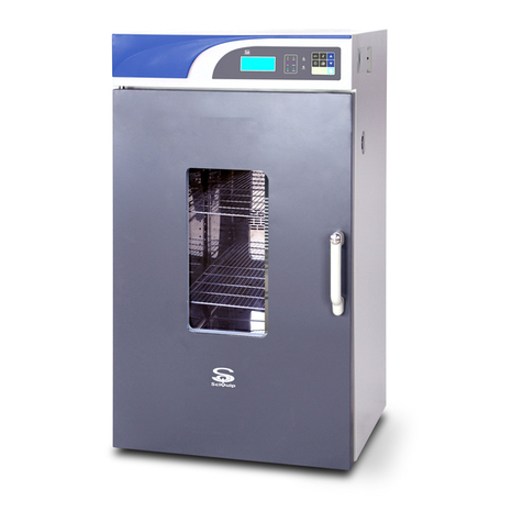
SciQuip Oven-HT Series User manual

User’s Manual
This Manual applies to:
Oven-HT series(horizontal airflow from back)
Oven-80HT/140HT/230HT
Oven-HT series
Blast Air Oven

SciQuip blast air oven has achieved good reputation and trust among various
clients for its advanced temperature controlling technology, sound framework design,
excellent exterior moulding and outstanding professional workmanship. This products have
been continuously exported to the dominant companies in Europe, America and East Asia.
Blast Air Oven applies dry heat to stopping microorganism oxygenation and protein
denaturation, affecting electrolyte concentration, hence, killing the residual microorganism
in some time.
The Blast Air Oven is widely used in the field of biochemistry, chemical pharmacy, medical
sanitation, agriculture and environment protection, etc. It is an ideal equipment for thermal
denaturation and induration of specimens, and the drying, sterilization, baking operations of
specimens like food, electronic components, building material, etc.
“SciQuip” thank you for your trust in its product!
Since the date of your purchase of this product, after-sale service will always be with you.
No matter what questions you meet in your using, please do not hesitate to contact us
whenever you want.
Safety instruction!
Thanks!
Thank you very much for your purchase of our Oven-HT series blast air
oven of which is specially designed for you. Your choice indicates
that you have very high requirement on style and performance of automatic
blast air oven.
Reminder
The manual should be read and understood thoroughly, because it
can help you to master the operating method and feature of this high-
tech product. Prior to operation, we strongly recommend you to read
this manual completely so that you can master all the function to the
utmost extent.

Safety instruction!
1.Grounding outlet to avoid accidental electric shock or fire disaster.
2.Do not attempt to repair the product yourself. Do not open the door of power box by
unprofessionals to avoid electric shock..
3.Please use the independent mains jack socket. Make sure the proper plug with outlet.
Loose connection will result in fire disaster caused by overheating.
4.Do not pull out the plug when it is operating. Do not drag the wire to plug the outlet.
5.Do not damage the wires or use the undesignated wires. Do not try to extend the wires or
attach wires at the middle by yourself. Improper handling of wires will result in fire or electric
shock.
6.Plug the outlet with wet will get risk of electric shock.
7.Do not put flammable or explosible object inside the chamber.
8.When in operation, the window of the equipment has a relative high temperature, so any
physical contact with it should be avoided.
9.To avoid burn, do not fetch the object inside the chamber until the temperature inside is
drop to normal, except security measure has been taken.
10.Do not put fingers, rods or other kinds of foreign bodies into the inlet or outlet of air.
11.In case of malfunction or burning smell, the unit must be immediately unplug and ceased
for further checking.
12.The electric power supply must be cut off under following situations:
12.1.When opening the door of power box.
12.2.When replacing the fuse.
12.3.When the malfunction occurs.
12.4.When not using for a long period of time.
12.5.When moving the equipment.
Danger!
Warnings against likely injury or death
Safety instruction!
Please be sure to follow the instructions, which are
really important for your safety.

!
I
1.The unit must be placed horizontally on solid, flat floors.
2.The unit must be provided with sufficient clearance on all sides of the unit, at least 20cm.
3.Do not leave the unit in a location exposed to direct sunlight or near heater.
4.The unit must be kept faraway from source of electromagnetic interference.
5.When in normal operation, culture inside the incubator should be placed to the extent of
which the air flow inside the equipment is not affected to keep the temperature uniformity in
the working chamber.
6.Make sure the shelf inside the chamber is horizontal.
7.Open or close the door heavily will probably leads to the damage of the equipment.
8.When in operation, do not open the door indiscriminately which will affect the temperature
inside.
9.The exterior of equipment must be kept away from volatile, flammable, explosive liquids or
gases.
10.Please keep the chamber clean. Regular cleaning is required.
Attention!
Instructions to keep the normal life and proper operations of
the equipment!
Attention!
Apart from the above warnings and instruction, there are several
other special reminder with a exclamation point within a
triangle, please read and follow. Any neglect will probably lead
to hidden trouble, serious damage, or accidental injury.
Attention!
Please close the door immediately after take/put the sample,otherwise the
temperature control precision could the affected.

Table of Contents
1.Key features 1
2. Technical Specifications 2
3. Control Panel 2
4. Preparation and Start-up 4
5. Setting of the Control Mode 4
6. Setting of the parameter under the constant
temperature control mode 5
7. Setting of the parameter under the programme control mode 7
8. Setting and Application of other functions 10
9. Operation and Switch Off 12
10. Electric theorem 13
11. Normal Malfunction and debugging 13

1
1. Key features
1.Individualized 10 segments, 18-step preset programmes achieve temperature preset
timing programs or reciprocating, stepped, ladderlike temperature running.
2.Sound heat insulation design and the transparent glass door meet European security
standard.
3.Automatic poweron and poweroff, timing operation, clock indicating, poweroff recovery,
parameter recalling and encryption, temperature indicating and correcting, RS-232 interface
and built-in microprinter.
4.Monitoring timer, independent exceeding guard, over temperature protector(adjustable).
5.Independent protector for electric leakage and over current.
6.Self-diagnosed techniques, such as power cut alarm, sensor failure alarm, and upper and
lower temperature limit exceeding alarm.
7.Highly responsive thermal sensor and environmental scanning microprocessor chip.
8.Three-dimensional heating technology ensures the solid temperature uniformity in the
working chamber.
9.Sound airway structure and gentle airflow circulation design.
10Unique design of chamber guaranties the cleanliness of the sample.
11.Mirror stainless steel chamber, electro polished stainless steel shelves and toughened
glass internal door.
12.The luxurious and elegant profile with aesthetic designing.
13.Air ventilation Adjustment
For discharge the excess humidity evaporation, the unit is equipped with a adjustable air
ventilation.
Turn the knob clockwise located on the right sidewall to open up air vent, or anti-clockwise to
close. Air vent located on the back wall.

2.Technical Specification
Model
Oven-80HT
Oven-140HT
Oven-230HT
Volume (L)
80
140
230
Heating Mode
Back Heating
Programmable Control
(9Segment/18 steps)
Standard
Temperature Range (°C)
Ambient+5 to 300
Temperature Accuracy
(°C)
0.1
Temperature Uniformity
(%)
< ±2.5% (@max temperature)
Display
LED
Alarm
Enabled
Timer (min)
1-999
Settings
Digital
Grids Included
2(max13)
2(max17)
2(max21)
Grid Size (mm) (WxD)
319*330
385*405
475*485
Chamber Dimensions
(mm) (WxDxH)
375*365*550
450*440*685
520*540*800
Exterior Dimensions
(mm) (WxDxH)
565*495*960
640*570*1095
720*670*1290
Packing Dimensions
(mm) (WxDxH)
650*590*1130
720*670*1255
800*720*1450
Net/Gross Weight (kg)
58/98
70/104
104/150
Power (W)
220V 50/60Hz
3. Control Panel
2

3
Change/Confirm button:
Press this button to display clock time. Hold on this button for 3 seconds to change the
parameter, and press this button again to confirm the change.
Increase button:
Press this button, the parameter will increase by one digit, the parameter will keep
increasing while this button is held on.
Decrease button:
Press this button, the parameter will decrease by one digit, the parameter will keep
decreasing while this button is held on .
Program button:
Press this button to set the program control parameter.
Temperature button:
Press this button to display the preset temperature, press this button again to confirm
the change.
Time button:
Press this button to display the operating time, press this button again to display the
preset time.
Operating button:
Under constant temperature control mode, press this button to start operation and press
it again to stop operation. Under programme control mode, press this button to start
operation and press it again to keep the status, hold on this button for 3 seconds to stop
operation.
Temperature exceeding alarm indicator:
When real temperature exceeds the upper or lower temperature limit, alarm will be
activated, this indicator will be light and the buzzer will keep alarming.
Heating indicator:
When the heater is connected with power supply, this indicator will be light. This
indicator will twinkle when the real temperature close to the preset value.
Real temperature Indicator:
When the screen is displaying the real temperature, this indicator will be light.
Temperature setting Indicator:
When the screen displays the preset temperature, this indicator will be light.
Time indicator:
When screen displays the operating time, this indicator will be light, twinkles when the
screen displays preset time.
Operating status indicator:
When the equipment is well functioned, this indicator will be light.
HEATING
SV
TM
RUN

4
Status keeping indicator:
Under program control mode, when the equipment is in the state of temperature keeping,
this indicator will be light.
Refrigeration indicator:
When the refrigerating system is working, this indicator will be on.
4.Preparation and Start-up
n and 1.After the equipment is positioned according to the points for attention, press down the
pressing board on the castor to fix so as to avoid any move when using.
2.Configuration of power supply of AC 220~240V 50/60Hz with capacity not less than the
power required in the specification. Use a dedicated jack socket for this equipment.
3.Connect the plug of power supply of the equipment with an independent jack socket.
4.Turn on the master switch on the right side of the equipment, power is applied to the
unit, the five digital tube displays the following in turn: PHTC3, Time, Real temperature.
Then the equipment is in the state of readiness.
5.Setting of the control mode
This equipment has two operating mode, i.e. constant temperature control and programme
control, users can choose one according to their need.
Hold on the “Change/Confirm” button for 3 seconds, the screen displays “CIP”and a second
later “0”, press the “Increase” button to input the password “1”, then press the “Change/Confirm”
button, the screen will display the original control mode: “Ctr=”means constant temperature
control, “CtrP”means programme control. Press the “Decrease” or “Increase”button to change
the control mode. Press the “Change/Confirm” button to confirm the change.
Attention:
Press the “Change/Confirm” button to display time. When in setting operation, If
the button is left untouched for 3 minutes, the screen will automatically switch to
display the real temperature.
HOLD
COLD
Attention!
Only use a properly grounded outlet, verify the local voltage of power
supply before start, we are not responsible for damages caused by
incorrect voltage of power supply.
PHTC3
25.1
10.25

5
Simplified instruction on the setting of control mode
6.Setting of parameter under the constant temperature control mode
1.Setting Temperature Parameter
Press the “Temperature”button to display the real value(one decimal), the green PV indicator turns on.
Press the “Temperature”button again, the screen displays the preset parameter(one decimal), the yellow
SV indicator turns on. Press the “Increase”or “Decrease”button can change the parameter.
2.Setting Time Parameter
Press the “Time”button to display operating time or the preset time delay switch on, the red TM indicator
turns on. Press the “Time”button again to display the preset timing parameter(minute, one decimal), the
red TM indicator twinkles. Press the “Increase”or “Decrease”button can change the parameter.
Press the “Time”button again, the screen will display the operating time(minute, one decimal), the red
TM indicator turns on. When in operation, the decimal point twinkles every second, the displaying time
increase by 0.1 every 6 seconds.
3.Press the“Change/Confirm” button to confirm the change.
Attention:
When the control mode is programme control, press “Programme”
button and the first digit displaying on the screen will be “P”.
Special Attention!
When the timing range is within 1-999 minutes and the parameter is
“0”, the equipment will work continuously.

6
Simplified instruction on the setting of constant temperature control mode
Below is a graph showing the relation under normal condition between
time and temperature when temperature keeps increasing. It can be
referred to when setting temperature and time.

7
7.Setting of parameter under the programme control mode
2.Every time the “Program”button is pressed, parameter symbol and number will be displayed
alternately on the screen, temperature(℃) and time(minute) have one decimal on display. Press the
“Decrease”or “Increase”button to set the temperature and time parameter. Refer to the graph two
to see the operating process.
1.P.SLO -The starting time parameter of the programme
2.P.tr1 -Heating time of the slope part of the first programme segment
3.P.SL1 -The ending temperature of the slope part of the first programme segment
4.P.td1 -Time of temperature retaining of the temperature retaining part of the first programme
segment
5.P.tr2 -Heating time of the slope part of the second programme segment
6.P.SL2 -The ending temperature of the second programme segment
7.P.td2-Time of temperature retaining of the temperature retaining part of the second programme
segment
The rest may be deduced by analogy
P.td9-Time of temperature retaining of the temperature retaining part of the ninth programme segment
P.Hb-Feedback value, condition for entering the retaining segment(℃, one decimal)
P.PLC-Cycle time(1-99)

8
Each program segment have two small segment, i.e. slope segment and temperature retaining segment
(refer to graph three), and consist of three parameter: the temperature ascending time of the slope
segment, the ending temperature of the slope segment, the temperature retaining time of the
temperature retaining segment. When the slope segment ends, program enters into the temperature
retaining segment, the setting temperature is the ending temperature of the slope segment. The ending
temperature of the last slope segment is the starting temperature of next slope segment. This equipment
has up to 9 program segment to set (9 slope segment + 9 temperature retaining segment). When you do
not need all the 9 segment, you can set the temperature ascending time of the next segment left unused
to be“-1”and the screen will display “End”.
Simplified instruction on the setting of program control time and temperature

9
3.When setting is finished and program parameter is not displayed on screen, press the “Operating”
button, the red operating indicator RUN turns on, the program begin running from the first program
segment. At this time, if screen is switch to display the preset temperature, the process in which
temperature changes with time canbe seen on the screen. If screen switch to display operating time, the
process of time change can be seen. When temperature and time are displaying on the screen, the first
digit tube displays the current program segment. When the slope segment is over and goes into the
temperature retaining segment, the yellow indicator HOLD turns on. When the ninth segment or the End
segment is over, operation stops, the screen displays “Stop”. When in operation, the control program
adjust the output incessantly to make the real temperature follow the preset temperature.
4.When in operation, press the “Operating” button to enter into the retaining state, the indicator RUN
twinkles, operating time is on hold, press the “Operating” button again to resume operation, the red
indicator turns on, the operating time continue to count . If the “Operating” button is held on for 3 seconds
at this time, operation will be stopped and screen displays “Stop”.
5.If you want to start operation from a randomly selected segment, press the “Program” button to display
the program segment, then press the “Operating” button when the segment you want is displayed on the
screen. The program begin operation from the segment displayed on the screen and take the current real
temperature as the starting temperature.
6.The setting and application of the parameter Hb (feedback value). Parameter Hb is the condition for
temperature to enter from the slope segment into the retaining segment. When setting of each program
segment is over, screen displays“Hb”(℃,one decimal), press the “Increase” or “Decrease” button to set
the Hb parameter. If the parameter is “0”, the slope segment ends and enter into the retaining segment
unconditionally. When the parameter is bigger than “0”and the deviation between the real temperature
and the preset temperature of the retaining segment is smaller than the Hb parameter, the program
re-enter into the retaining segment and the retaining time begin to count.
7.The setting and application of the parameter PLC(cycle time). When in program operation, this
equipment has a cycle time of 1-99. Setting method: Press the “Program” button until the screen displays
the “P.PLC ”and number alternately, press the “Increase”or “Decrease” button to set the cycle time.
When the time of slope segment or retaining segment of a certain program segment is “STEP”(when the
screen displays “End”, subtract 1 one more time) and program reaches this segment, the cycle time
subtract 1, program jump to the first segment to renew operation in cycle. When cycle time reduce to “0”,
program skip the cycle and run the next segment of “STEP”. When in operation and operating time is on
display, hold on the ‘Decrease“ button to display the balance cycle time.
Attention!
When the Hb parameter is “0”, the slope segment ends and enter into
the retaining segment unconditionally.

10
8.Setting and Application of other functions
1.Setting of the delayed time of turning on the equipment
This equipment can achieve time delay switch on. When the parameter of time delay is not “0”, the
equipment can switch on automatically after time delay.
Hold on the “Change/Confirm” button for 3 seconds, screen displays “CIP”, a second later “0”, press the
“Increase”button to input the password “2”, press the “Change/Confirm” button again and the screen will
display the delay time to switch on the equipment, the symbol “ddtl”and number displays alternately on
the screen(minute,one decimal), press the “Increase”or “Decrease”button to set the parameter, press the
“Change/Confirm” button to confirm the change. Press the “Operating”button at this time, the yellow
indicator HOLD turns on and the preset time begin to count down. When time reduce to “0”, indicator
HOLD turns off, operation begins, the red operating indicator RUN turns on(Under programme control
mode, operation of programme segment begins.).
Simplified instruction on the setting of time delay switch on
2.Setting of the temperature exceeding alarm
Hold on the “Change/Confirm” button for 3 seconds, screen displays “CIP”, a second later “0”, press the
“Increase”button to input the password “3”,press the “Change/Confirm” button again, screen displays
symbol and number alternately:
1)Prnt( the use of interface of printer)
2)ALH(upper limit alarm value, ℃, one decimal) When the real temperature reaches this value, the
equipment cut off the heating output automatically thus stop the operation. Press the “Increase”or
“Decrease”button to change the ALH value, then press the“Change/Confirm” button again to confirm
the change.
Attention!
When the parameter of time delay is not “0”, the equipment can
switch on automatically after time delay.
Special Attention:
The upper limit alarm valuemust be larger than thepreset temperature.

11
3)ALHC(The alarm value of deviation of real temperature and the setting temperature, ℃, one decimal)
When real temperature is beyond this value, the equipment alarms continuously and the alarm indicator
turns on, heating output is automatically cut off. Press the “Increase”or “Decrease”button to set this
parameter, press the “Change/Confirm” button again to confirm the change.
Simplified instruction on the setting of temperature exceeding alarm
3.Setting of the clock
Press the “Change/Confirm” button to display the clock on the screen. The clock time can be changed
when deviation between clock and standard time occurs.
Hold on the “Change/Confirm” button for 3 seconds, screen displays “CIP”, a second later “0”, press the
“Increase”button to input the password “4”, press the “Change/Confirm” button again, screen displays
the hour value, press the “Increase”or “Decrease”button to change the hour value, press the
“Change/Confirm” button one more time, screen display the minute value, press the “Increase”or
“Decrease”button to change the minute value, press the “Change/Confirm” button at last to confirm the
change.
Simplified instruction on the setting of time
Attention!
1.When this ALHC value is “0”, equipment will not alarm.
2.Change the preset temperature or enlarge the ALHL value can terminate the
temperature exceeding alarm.
3.When deviation is back to the range you set, the equipment terminate the
temperature exceeding alarm automatically.
4.Press the “Operating”button can make the equipment stop running.

12
9.Operation and Switch off
1.When the above setting is finished, press the “Operating”button and the equipment runs
according to the designed programme, the red operating indicator RUN turns on.
2.When the equipment is in the state of temperature control or programme control, the red
heating indicator turns on or twinkles means the heating is connected and it is normal.
3.When in operation, if you need to change parameter, press the “Operating”button to stop
running, change the parameter after the operating indicator turns off.
4.When in operation, the operating time increases and twinkles by second. When operating
time reaches the preset value, heating output will be stopped, the operating indicator turns off.
At this time, the power control transformer isstill connected to power supply, so turn off themain
switch on the right side of the equipment to switch off the equipment.
4.Power-off recovery
This equipment has power-off recovery function.
When the external power is recovered after a
sudden cut off and the deviation of temperature
inside is within 2℃, the equipment can
automatically recover to run according to the
originally designed programme
.
5.Air ventilation Adjustment
For discharge the excess humidity evaporation,
the unit is equipped with a adjustable air
ventilation.
Turn the knob clockwise located on the right
sidewall to open up air vent, or anti-clockwise to
close. Air vent located on the back wall.

13
10.Electric theorem
11.Normal Malfunction and debugging
Encountered
symptoms
Possible cause
Debugging
Power on without display
1. Power supply is not cinnected
2. Block have access to jack socket
3. The power switch have not been
turned on
4. The fuse is broken
5. Malfunction of power box circuit
occurs
Check the power supply system to see if there is
voltage
Plug the equipment firmly
Turn on the power switch on the right side of the
equipment
Replace the fuse with new one of same
specification
Notify the manufacturer for repair service
Equipment enter into the state
of temperature exceeding
alarm
1. Equipment has not yet enter into the
state of constant temperature
2. Setting of the parameter is
unreasonable
3. Malfunction of heating system
occurs
Wait a minute and observe for a while
Refer to the operating procedure and change or
re-set parameter
Notify the manufacturer for repair service
Real temperature is lower than
the setting temperature, thus
activate the lower temperature
deviation alarm
1. Equipment has not yet enter into the
state of constant temperature
2. Temperature deviation alarm value
is too small
3. Abnormal condition occurs with the
heater
Wait a minute and observe for a while
Reset the alarm value
Notify the manufacturer for repair service
Screen displays nothing or
lack of stroke or distortion
1. Equipment is disturbed by high
frequency
2. Eliminate the source of disturbance
and restart the operation
3. Block has access to displaying
circuit
Eliminate the source of disturbance and restart
the operation
Refer to professionals for check or repair service
Notify the manufacturer for repair service
This manual suits for next models
3
Table of contents
Other SciQuip Oven manuals