Scotsman DC33 User manual

Introduction
The Scotsman RF33 Compact Refrigerator is a
unique product, capable of being built into a
cabinet because of its front vented, forced-air
cooling system.
It’s also designed to be a companion to
Scotsman’s DC33 Automatic Ice Machine. To
prevent door interference when installed to the left
of a DC33, the RF33 comes from the factory with
the door hinged on the left. The door swing may
be reversed to suit the installation.
The RF33 keeps its interior cool by removing heat
from the freezing compartment at the top of the
storage area and exhausting that heat out the right
front grill.
Table of Contents
Specifications . . . . . . . . . . . . . . . . . . . . . . . . . . . . . . . . page 2
Installation . . . . . . . . . . . . . . . . . . . . . . . . . . . . . . . . . page 3
Customizing . . . . . . . . . . . . . . . . . . . . . . . . . . . . . . . . . page 4
Reversing door swing . . . . . . . . . . . . . . . . . . . . . . . . . . . . . page 5
Installation & Operating . . . . . . . . . . . . . . . . . . . . . . . . . . . . page 6
Routine Maintenance . . . . . . . . . . . . . . . . . . . . . . . . . . . . . page 7
Problems . . . . . . . . . . . . . . . . . . . . . . . . . . . . . . . . . . page 8
Specialized Service . . . . . . . . . . . . . . . . . . . . . . . . . . . . . . page 9
This product manual is intended to be a resource
for installation, routine maintenance, and service
diagnosis.
Although there have been several changes in
appearance and components, this manual covers
all models of the RF33.
Aparts list is located in the center of this manual,
printed on colored paper.
Note the warning symbol where it appears in this
manual, it is an alert that there may be some
hazard noted in that section of the manual.
Keep this manual for future reference.
This manual was printed on recycled paper.
Scotsman reserves the right to make design changes
and/or improvements at any time. Specifications and
design are subject to change without notice.
RF33
November 1992
Page 1

Specifications of RF33A-1WA:
Cabinet dimensions are critical to a built in
installation. The diagrams illustrated below show
the details of the cabinet construction.
Note: Right and Left
Placement of Machines Will
Not Affect Performance.
1/2"
1.3 cm
2"
5.1 cm
29 7/8"
74.0 cm
4"(10.2 cm)
to bottom of
legs
Capacity Insulation Compressor Condenser Type
3 + cubic feet 1" foamed in place
polyurethane 1⁄16 H.P. Forced Draft
RF33
November 1992
Page 2

Installation:
After the carton has been removed, check for any
concealed damage. Check the unit interior and
exterior. After this check, the unit may be installed.
Open the door and remove all packing materials,
including warranty packet, tape, and warranty
registration. Note: Keep the filler plate for use
when reversing door swing.
Wipe the interior of the cabinet with soap and
water to remove any manufacturing or shipping
residue.
The RF33 will work fine as a free standing
refrigerator, minimal attention to leveling, electrical
power supply and no obstruction of air flow will
provide an adequate environment.
The RF33 is only designed to be operated indoors.
Malfunctions due to outdoor operation will not be
covered by warranty.
Excessive heat (over 100oF.) will cause poor
performance.
When built in, some precautions must be taken:
Size: The space occupied by the refrigerator is:
••15 1⁄4" wide (including screw heads at the base)
••24" deep to the front edge of the door handle
••33 3⁄8" high (33 7⁄8" to the top of the door hinge).
There is a kick plate at the bottom front of the
cabinet, the louvers in that kick plate allow air
to flow through the cooling mechanism, and
those louvers must not be blocked at any time.
The cabinet legs should be flush with the floor, so
that the refrigerator may be pulled out without
damage to the floor.
The electrical supply must be near enough so that
an extension cord is not used. The power
requirements are 115 volts AC, 60 cycle, single
phase (normal U.S. house current). Scotsman
recommends that the refrigerator not be connected
to a circuit with high amperage equipment already
on it. Check with a licensed electrician for
recommendations. Be sure to follow all applicable
electrical codes.
The RF33 is UL listed, meaning it has met certain
requirements for electrical safety. Any modification
or substitution of components may violate those
requirements, and Scotsman will not be
responsible for any RF33 so modified. Always use
Scotsman replacement parts.
Air Flow of RF33
Air In Air Out
Kickplate
RF33
November 1992
Page 3

Customizing Door Panel:
Acustom door panel may be installed in front of
the standard one. Any panel 14 3⁄4" wide, 28 15⁄16"
high and 1⁄4" thick or less at the edges may be
used as a decorator panel. Examples of decorator
panels include wood to match the adjacent
cabinets; metal of different colors to match nearby
appliances; or just about any material that will fit.
Scotsman has a stainless steel panel available to
fit this machine, the kit number is SS33. If the
material is less than 1/4" thick, the space between
the new panel and the original may be filled with
cardboard.
1. Remove single screw and the left hand hinge
filler plate from the top of the door.
2. Remove two screws from the top of the door
and lift off the door handle.
3. Open the door slightly, about one-third
or so; then, remove the front screw holding
the hinge to the door.
4. Loosen the rear screw of the hinge just
enough to allow the door to sag or move
forward. This will allow access to the top of
the channels at the right and left edges of
the door.
5. From the top of the door, insert the
decorator panel (pre-cut) evenly into the
channels; carefully slide the panel all the
way down until the panel is fully into the
bottom channel.
6. Check that the panel is the in all the
way and does not protrude past the top
edge of the door.
7. Push the top hinge corner of the door IN
to align screw hole in the hinge with the
screw hole in the door. Install the screw
previously removed. Tighten the other
screw.
8. Replace the door handle and filler plate;
secure with screws previously removed.
Note: These Two Kits Are Currently
Available to Change Panel Color:
TP33 contains 2 sandalwood panels.
WP33 contains 2 white panels.
Hinge filler
plate
Custom Panel,
Thin Panel
Shown With
Filler.
Parts Involved in Customizing Door Panel
Hinge
Door with
groove
Door Handle
RF33
November 1992
Page 4

Reversing Door Swing:
The RF33 was shipped with the door hinged at the
left. The door and hinges are designed for placing
the hinges on either the right or the left side of the
cabinet. Moving the hinges to the right allows the
door to pivot from the right side.
Note: There is a part, packed with the machine,
that is required for this procedure.
1. Open the door and remove the three screws
holding the lower hinge to the cabinet.
2. With the door open enough to see both screws
at the top door hinge, remove the two screws. The
door is now free of the cabinet.
3. Remove the single screw and the hinge filler
plate from the top of the door.
4. Install the other filler plate (shipped inside
refrigerator compartment) onto the top corner of
the door where the hinge was.
5. Remove the three plastic plugs from the top
front corner where the hinge will mount.
6. Remove the three plastic plugs from the lower
front corner where that hinge will mount.
7. Remove the three screws holding the top hinge
to the cabinet. Remove that hinge from the top
and, flipping it upside down, install it onto the
bottom of the door, on the opposite side using the
original screws.
8. Remove the hinge assembly from the bottom of
the door, and flip it upside down; secure it to the
cabinet at the opposite side top position with the
original screws.
9. Hold the door up to the cabinet. Secure the door
to the top hinge with the original screws.
10. Secure the bottom hinge to the cabinet with
the original screws.
11. Place the plastic plugs removed earlier into the
empty holes.
12. Check operation of the door by opening and
closing it.
Door Handle
Filler Plate
Hinge
Hinge
Magnetic
Gasket
Door
Reverse Hinges From Top to Bottom and Left to Right To
Reverse Door Swing
RF33
November 1992
Page 5

Installation
The machine should not be installed in a room that
falls below 50oF.
Level the cabinet by turning the leveling legs at the
base of the refrigerator.
Plug the refrigerator into the electrical power
supply.
Do not slide into place until the unit has been
started.
Operation:
To begin operation: Open the door, locate the
temperature control knob in the upper right portion
of the interior and rotate that knob clockwise until it
is about at the mid position.
The compressor and fan motor should both be
operating, unless the refrigerator is below 35oF.
Check that air is flowing out the right side of the
grill.
The metal portion of the freezing compartment will
soon feel cold. That is the signal that the
refrigerator is functioning and the cabinet may now
be placed in its installed position.
The refrigerator will require some
time to cool the air and cabinet
interior. If desired, a thermometer
may be placed in the interior and
the temperature checked. The
RF33 should maintain
approximately 40oF. interior
temperature.
Note: As warm products are
placed in the refrigerator, the
refrigerator will likely operate for
some time to cool them. When the
refrigerator is empty, it will switch
on and off frequently because
there’s only air inside, and the
temperature of the air changes
quickly.
The temperature of the
Refrigerator may be adjusted by
rotating the temperature control
knob: Turn the knob clockwise for
colder and counterclockwise for
warmer.
Placing ice trays in the freezing
compartment will reduce
refrigerating capacity.
Use: The refrigerator is
permanently lubricated, no oiling is
required. There are two things that
do require periodic maintenance:
The air cooled condenser and the
build up of frost on the freezing
compartment.
Temperature
Control
Plastic Drip
Tray
Freezing
Compartment
Location of Temperature Control
RF33
November 1992
Page 6

Routine Maintenance & Cleaning
General recommendations are to keep the interior
clean by occasionally washing it out, and if
anything should spill inside, wiping up the spill
immediately.
The condenser is a coil at the bottom of the
machine where air flows through to exhaust the
heat from the cabinet. The condenser should be
cleaned at least twice a year. The freezing
compartment should be defrosted whenever 1⁄4" of
frost has built up on it.
1. Condenser cleaning: The cleaner the condenser
is the less time the refrigerator will have to operate
to keep the interior at the correct temperature.
A. Remove screws and the kickplate at the bottom
of the cabinet.
B. Locate condenser on the left side, earlier
models had the condenser near the front, current
models have it near the back. Use a vacuum
cleaner with an attachment that can reach the
condenser. Vacuum up all lint and dust visible on
the condensers fins.
2. Defrosting: Frost will build up on the freezing
compartment, this is normal. The frost must be
periodically allowed to melt off or the refrigerator
will become ineffective and operate for very long
periods to try to maintain the set temperature.
A. Open the door and remove all items stored in
the refrigerator.
B. Remove any ice tray (if used) from the freezing
compartment.
C. Check that the plastic tray below the freezing
compartment is in place and empty.
D. Push the button located in the center of the cold
control IN.
This starts the Defrost cycle. If there is substantial
frost build up the tray under the freezing
compartment will not hold all the water, and must
be emptied; check the defrost every few hours.
The RF33 will automatically return to the
refrigeration cycle when defrost has been
completed. Note: This may take up to 24 hours, so
alternate storage of perishables is required.
Caution: Do not scrape or pry ice/frost off the
freezing compartment. It is very vulnerable to
penetration by sharp objects and if pierced, the
refrigerator will loose its refrigerant and will require
extensive service.
The most convenient time to clean the interior is
after defrosting the freezing compartment.
Defrost
Button
Condenser
Kickplate
Location of Condenser
RF33
November 1992
Page 7

Before Calling For Service:
The refrigerator is a very simple machine. Normal
use should not require technical service. If there is
a problem with the refrigerator, refer to this chart
before calling for service.
Problem Possible Cause Probable Solution
Refrigerator will not operate Not plugged in Plug in
Breaker tripped/fuse blown Reset breaker, replace fuse
check operation. If breaker trips or
fuse blows again, unplug
refrigerator and reset breaker or
replace fuse. If circuit does not fail
again, call local Scotsman Service.
Thermostat not turned cold
enough Rotate knob until unit starts. If unit
does not start, call local Scotsman
service.
Interior does not get cold enough. Thermostat set too high Rotate to colder position.
Dirty condenser Clean condenser
Frosted freezing compartment Defrost freezing compartment
Door gasket worn Replace door gasket
Cabinet in very warm space Relocate or remove excess heat.
If none of the above will correct
the problem, call local Scotsman
service.
Gets too cold inside Thermostat set too low Rotate knob counterclockwise
Thermostat defective Call local Scotsman service.
Will not defrost. Faulty thermostat Call for local Scotsman Service
Makes excessive noise Fan motor worn Call for local Scotsman service
RF33
November 1992
Page 8

Specialized Service:
The following procedures are for the qualified
service technician only.
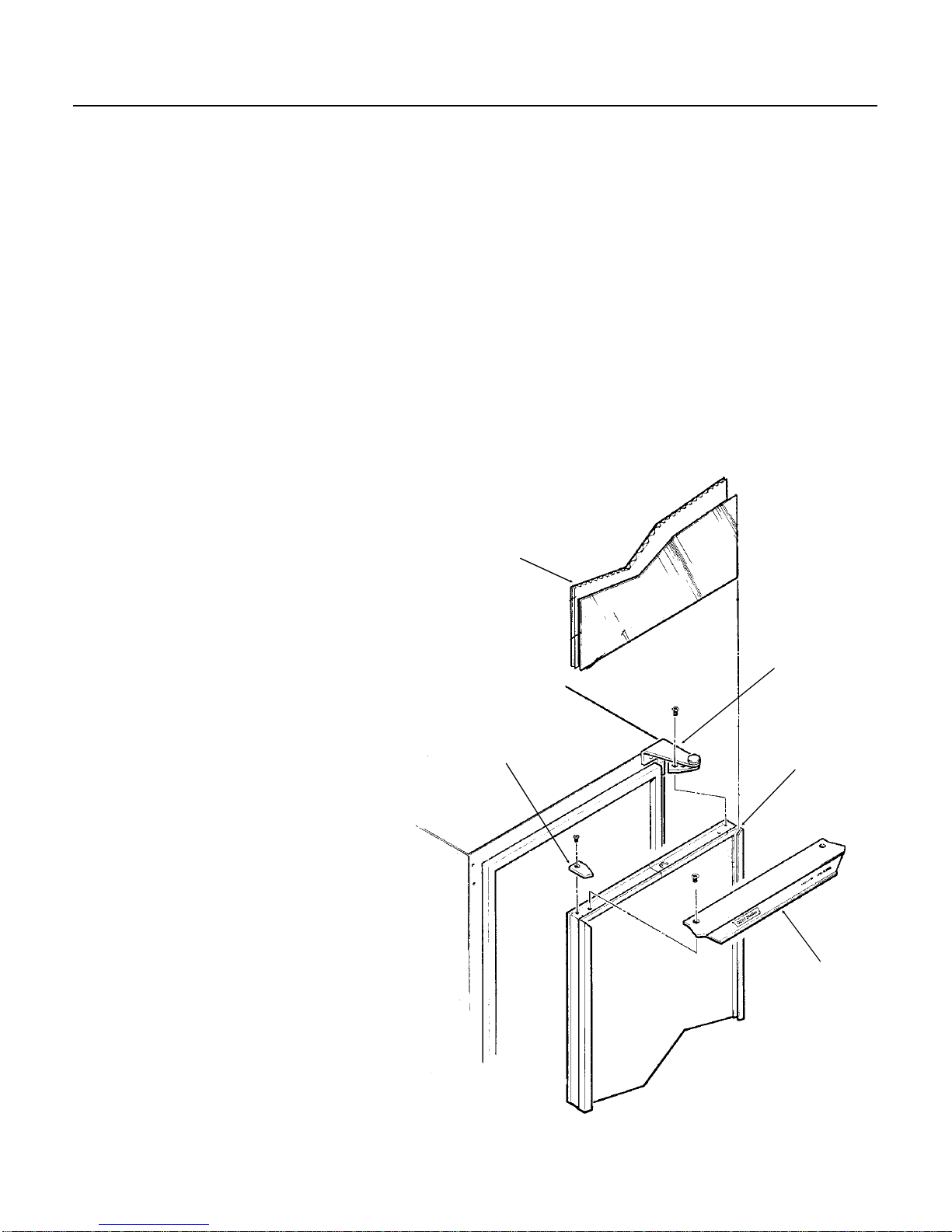
Thermostat
1. Unplug refrigerator from electrical power.
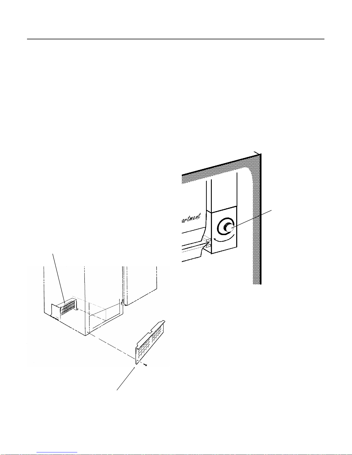
2. Open the door and pull the plastic tray out from
under the freezing compartment.
3. Lift the freezing compartment door and locate
the hinge wire behind the right side of that door.
Carefully push the hinge wire toward the center of
the door until the end of the wire has been pulled
out of the hole in the upper left wall of the
thermostat housing. Do not loose the plastic
spacer.
4. Remove the left hinge wire and spacer from the
left wall of the refrigerator liner.
5. Remove any ice trays that may be in the
freezing compartment.
6. Remove the screw and bulb holder clip to free
the end of the thermostat capillary tube from the
rear of the evaporator.
7. Remove the knob from the thermostat (pull
forward).
8. Remove two screws (retain spacers) and
separate the thermostat housing from the freezing
compartment (evaporator).
9. Remove two screws attaching the top left flange
of the thermostat housing to the inner ceiling of the
refrigerator liner.
10. Remove two screws holding the lower right
flange of the thermostat housing to the right side
refrigerator liner. The capillary tube should be free
for removal. Lower the housing until the wire
connections to the thermostat can be seen.
11. Remove the two screws from the front of the
thermostat housing and separate the housing from
the thermostat. Remove it from the unit.
12. Remove the single screw from the bottom of
the electric baffle base and cover and remove the
cover.
13. Note the position of the wires, and disconnect
the three electrical wires from the thermostat.
14. Remove the thermostat housing and
thermostat from the cabinet.
15. Separate the thermostat from the electric
baffle, pull the capillary tube out through the hole
in the rear of the left wall of the thermostat housing.
16. Reverse the above to replace.
Fan Motor
Note: Machine must be pulled out from the
installed position, and the back panel removed to
gain access to the fan motor or compressor.
1. Unplug machine from electrical power.
2. Disconnect electrical leads from fan motor at
connections.
3. Lift the cabinet up to gain access to the screws
under the base, and remove the two screws
holding the fan motor bracket to the base.
4. Lower the cabinet, and remove the fan motor
and bracket from the base.
5. Replace fan motor or blade as required.
Reverse to reassemble.
Electrical shock
hazard.
Disconnect electrical
power before beginning
service.
RF33
November 1992
Page 9

Refrigeration:
Only qualified service technicians should work on
the refrigeration system. Recovery techniques
should be used where required for the amount of
refrigerant in the system. Refrigeration ports are
not part of factory construction. Asuction side port
must be added to service the refrigeration system.
The compressor process tube is a good place to
add the port. Do not add a discharge side port, as
the minimal charge will be affected by the added
space.
Note: prior models use an aluminum condenser
with copper stubs, very careful heat sinks are
required to braze at those connections. An
example could be a flare block clamped over the
aluminum tubing of the condenser. Current models
use copper tube condensers.
The evaporators are also aluminum.
Always use a new drier whenever the sealed
refrigeration system has been opened.
Check the parts list for the correct compressor, fan
motor, blade and condenser.
Replacement of the compressor or condenser is
best done by removing the cabinet from the base.
This requires that the tubing connections to the
evaporator be cut. Removal of the screws at the
side of the base will allow the cabinet to be lifted
up and off the base.
Refrigerant charge for RF33A-1Ais 1.75 ounces of
R-12.
Refrigerant charge for RF33A-1WA-1Ais 2 ounces
of R-12.
RF33
November 1992
Page 10
Other manuals for DC33
1
This manual suits for next models
1
Table of contents
Other Scotsman Refrigerator manuals
Popular Refrigerator manuals by other brands

Whirlpool
Whirlpool GI6SDRXXQ cabinet parts

KitchenAid
KitchenAid KBFS25EVBL - 24.8 cu. ft. Refrigerator parts list

GE
GE GSH22JFXCC - Refrigerator w/ Glass ESTAR Dimensions and installation information

AEG
AEG SCT51800S0 user manual

Beko
Beko RCSA330K30XPN Instructions of use

GE
GE GTH18IBXWW - R 18.0 Cu. Ft. Top-Freezer... Dimensions and installation information