manuals.online logo
Brands
  1. Home
  2. •
  3. Brands
  4. •
  5. Panasonic
  6. •
  7. Stereo Receiver
  8. •
  9. Panasonic SG-J500 (K) User manual

Panasonic SG-J500 (K) User manual

This manual suits for next models

1

Other Panasonic Stereo Receiver manuals

Panasonic SAEX320 - RECEIVER User manual

Panasonic

Panasonic SAEX320 - RECEIVER User manual

Panasonic SAHE200 - RECEIVER User manual

Panasonic

Panasonic SAHE200 - RECEIVER User manual

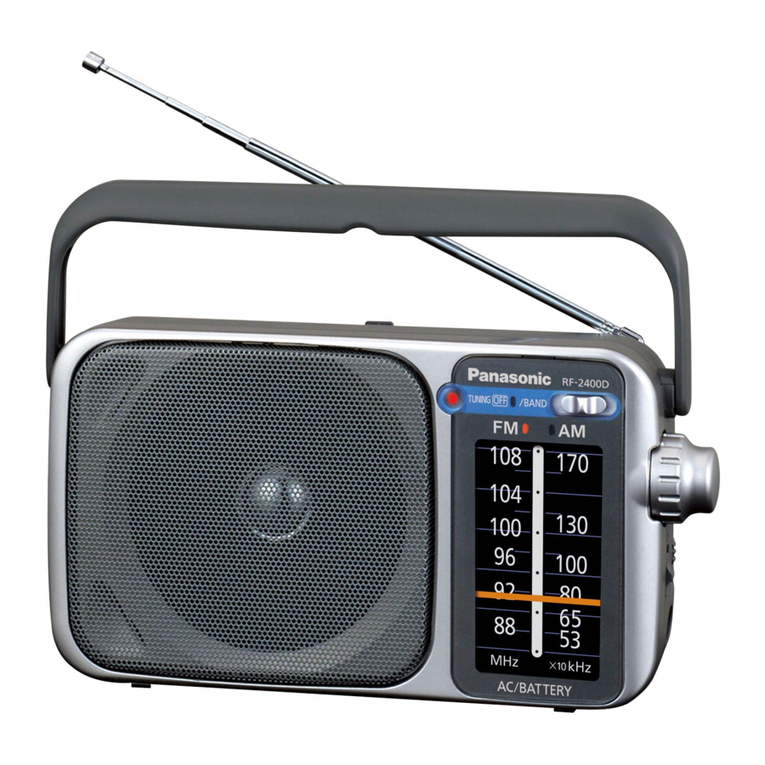
Panasonic RF-2400D User manual

Panasonic

Panasonic RF-2400D User manual

Panasonic SA-XR55E User manual

Panasonic

Panasonic SA-XR55E User manual

Panasonic RF-U700 User manual

Panasonic

Panasonic RF-U700 User manual

Panasonic RF-SW200 User manual

Panasonic

Panasonic RF-SW200 User manual

Panasonic SAHE200 - RECEIVER User manual

Panasonic

Panasonic SAHE200 - RECEIVER User manual

Panasonic SAHE70 - RECEIVER User manual

Panasonic

Panasonic SAHE70 - RECEIVER User manual

Panasonic SAHT210 - RECEIVER User manual

Panasonic

Panasonic SAHT210 - RECEIVER User manual

Panasonic SAHT210 - RECEIVER User manual

Panasonic

Panasonic SAHT210 - RECEIVER User manual

Panasonic HDMI SA-XR70E User manual

Panasonic

Panasonic HDMI SA-XR70E User manual

Panasonic SC-HT260 Operating User manual

Panasonic

Panasonic SC-HT260 Operating User manual

Panasonic SAHE200 - RECEIVER User manual

Panasonic

Panasonic SAHE200 - RECEIVER User manual

Panasonic SC-PM500 User manual

Panasonic

Panasonic SC-PM500 User manual

Panasonic RF-SW150 User manual

Panasonic

Panasonic RF-SW150 User manual

Panasonic CQ-LA1923L Building instructions

Panasonic

Panasonic CQ-LA1923L Building instructions

Panasonic SAHT220 - RECEIVER User manual

Panasonic

Panasonic SAHT220 - RECEIVER User manual

Panasonic SA-DT310E User manual

Panasonic

Panasonic SA-DT310E User manual

Panasonic SAAX730 - RECEIVER User manual

Panasonic

Panasonic SAAX730 - RECEIVER User manual

Panasonic SC-NS55 - Micro System w/ CD Player Home... User manual

Panasonic

Panasonic SC-NS55 - Micro System w/ CD Player Home... User manual

Panasonic SG-250R/25Q User manual

Panasonic

Panasonic SG-250R/25Q User manual

Panasonic SA-XR55E User manual

Panasonic

Panasonic SA-XR55E User manual

Panasonic RQ-V460 User manual

Panasonic

Panasonic RQ-V460 User manual

Panasonic AJSD955B - DVCPRO50 STUDIO DECK User manual

Panasonic

Panasonic AJSD955B - DVCPRO50 STUDIO DECK User manual

Popular Stereo Receiver manuals by other brands

Teac AG-680 Service manual

Teac

Teac AG-680 Service manual

Kenwood KR-V888D instruction manual

Kenwood

Kenwood KR-V888D instruction manual

Teac AGV1050 owner's manual

Teac

Teac AGV1050 owner's manual

Sony STR-435 operating instructions

Sony

Sony STR-435 operating instructions

Pioneer Elite SC-68 Service manual

Pioneer

Pioneer Elite SC-68 Service manual

Pioneer SX-1250 operating instructions

Pioneer

Pioneer SX-1250 operating instructions

Marantz CINEMA 70S owner's manual

Marantz

Marantz CINEMA 70S owner's manual

Kenwood KMDX92 instruction manual

Kenwood

Kenwood KMDX92 instruction manual

Yamaha RX-830 owner's manual

Yamaha

Yamaha RX-830 owner's manual

Pioneer AVH-Z7250BT owner's manual

Pioneer

Pioneer AVH-Z7250BT owner's manual

Denon AVR-1311 owner's manual

Denon

Denon AVR-1311 owner's manual

Denon AVR-S760H owner's manual

Denon

Denon AVR-S760H owner's manual

Denon AVR-X7200W Service manual

Denon

Denon AVR-X7200W Service manual

Sony XAV-1500 operating instructions

Sony

Sony XAV-1500 operating instructions

Radio Shack DX-399 owner's manual

Radio Shack

Radio Shack DX-399 owner's manual

Sony STR-DE535 - Fm Stereo/fm-am Receiver operating instructions

Sony

Sony STR-DE535 - Fm Stereo/fm-am Receiver operating instructions

Pioneer SX-1000TA operating instructions

Pioneer

Pioneer SX-1000TA operating instructions

Yamaha MusicCast TSR-5B3D owner's manual

Yamaha

Yamaha MusicCast TSR-5B3D owner's manual

manuals.online logo
manuals.online logoBrands
  • About & Mission
  • Contact us
  • Privacy Policy
  • Terms and Conditions

Copyright 2025 Manuals.Online. All Rights Reserved.

Service
Manual
MW/FM
STEREO
RADIO
WITH
CASSETTE
TAPE
DECK
AND
RECORD
PLAYER
ORDER
NO.
SD83072600C2
Portable
Stereo
SG-J500
(K),
(W)
[EX]
[EX]:
Denmark,
Specifications
AMPLIFIER
SECTION
POWer
OUtPUt
.....05..cisvsnssiccsereseess
AC:
MPO
4W
x
2
(THD
10%,
62)
RMS
1.9W
x
2
(THD
10%,
6)
DC:
RMS
3W
x
2
(THD
10%,
62)
FM
TUNER
SECTION
Frequency
Rangeé.............::cecceeees
87.5
MHz
~
108
MHz
Intermediate
Frequency
(IF)............
10.7
MHz
Sensitivity
..
2.8
uV
(at
1
kHz,
40
kHz)
(DIN)
at
752
Stereo
Separation..............ecee
34
dB
(at
1
kHz,
60
dB,
40
kHz)
AM
TUNER
SECTION
Frequency
[email protected]:cccceeees
525
kHz
~
1605
kHz
(571m
~
187
m)
Intermediate
Frequency
(IF)............
450
kHz
SONSIIVIRY
<scccicsrsiveseccssesssncenccaazerevees
220
uV/m
(1
MHz)
TAPE
DECK
SECTION
Deck
System
isccccsicsesssssssernceossoantonny
Auto
stop
Track
System.
...
4-Track,
2-Channel
Head
Type.
.....
..
Hard
Permalloy
(Rec/Play)
Double
Gap
Ferrite
(Erase)
Recording
System
...........:::c:eeee
AC
Bias
(50
kHz)
Erasing
System..
..
AC
Erase
(50
kHz)
Tape
Speed...........
..
4.8
cm/sec.
Frequency
Response
..
50
Hz
~
12
kHz
Signal/Noise
Ratio
..
50
dB
(DIN)
WOW
SclFIUtteh
ni
c.cesecvascccccesssonisncs
0.2%
(WRMS)
Panasonic
Finland
PHONO
SECTION
Turntable
System
..........ccccccceeeeeee
Belt
drive
Turntable
Platter...
.
16cm
Turntable
Speed
..............cccceceeeeee
33-1/3
rpm
and
45
rpm
PRONO-MOtOl
..sscisersissscvessesseccacsunns
Electro-Governor
DC
Motor
Cartridge
..
Ceramic
cartridge
(EPC-13STH)
RPI
ass
casted
cevesnaneuivecchseemeeoniaiensiseadk
Sapphire
tip
(EPS-41ST)
Stylus
Pressure
Range..............05
5.99
SPEAKER
SYSTEM
SHOGNOE
siccccicccnetnnuutiinneteianuiies
12
cm
Dynamic
Speaker
Input
Impedance.................
eee
62
GENERAL
Power
Consumption...................005
15W
Power
Supply
wciccisscsrcsssccessssssnsvescees
AC
110V/120V/220V/240V,
50/60
Hz
Battery:
12V
(8
x
UM-1,
“D”
size
battery)
Car
battery:
optional
car
adaptor
395
mm
x
273
mm
x
209
mm
WIGKE
vice.
cciecsascscveroivancucexeusbegrecs
5
kg
(without
batteries)
5.8
kg
(with
batteries)
*
Specifications
are
subject
to
change
without
notice
for
further
improvement.
Matsushita
Electric
Trading
Co.,
Ltd.
P.O.
Box
288,
Central
Osaka,
Japan
CONTENTS
Page
Page
SPOCIPICATIONS..........ccececccneeesserceeetessceadencccsseasseeceneeeeeesenssoees
1
IE
BIO
CK
DAG
GAIN
seicaicscin
cise
sosenstonwonaudeehatarmnuncbedevnumueen
dienes
3
OCAUSIT
OF
COMUOIS
i
css
schoncatcadeedanracenededendendeucoulwenniconel
eters
Z.
Parts
Location
of
Cabinet
and
Chassis................000000
15
Disassembly
Instructions
................ccccccceeeeeeceeeeeeeeeeeeeeeeeees
3
Replacement
Parts
List
of
Cabinet
and
Chassis...............
16
Measurements
and
Adjustment
...............:::ccceeeeeeeeeees
4~6
Parts
Location
of
Record
Playet.....................00.cccccecceeseeees
17
Tape
Deck
Service
Aid............cceceeececccceceeteeeeeeeettteeeeeeeeees
6
Replacement
Parts
List
of
Record
Player..............0000.00
17
WIRING
(COMME
CHO
NS
:oeaseasextocecentives
seeoasnseredsaecneemaymacnonenacensets
Parts
Location
of
Cassette
Tape
Deck...
18
Replacement
Parts
List
Replacement
Parts
List
of
Cassette
Tape
Deck...
«ws
19
SCHEMATIC
DIAQa
Mes
nescevcerseass
cexsonuescxnnss
vested
teeseedmesnrateta:
BIOGK:
Dia
G
Pani
sicsosscdassnaddacass
tuesecensdnadscaabamuatnesinesaaneastaisvans
20
Circuit
BOard
00...
0.00...
ccccceccce
cece
eeeeceecesesuueeessessseeesssaneseuaees
LOCATION
OF
CONTROLS
Volume
Control
i
Cassette
Button
(
pare
stop/eject,
|
,
rew,
play,
rec
Mic
Jack
Headphone
Jack
Tuning
Control
Player
Lid
Tone
Control
Player
Open
Button
Function
Button
(
apap
ened
ye
)
Telescopic
Ant.
AC
IN
Jack
DC
IN
Jack
(13.2
V)
Voltage
Selector
ae
-
:
Accessory
Box
DISASSEMBLY
INSTRUCTIONS
@
Remove
the
Power
Cord,
Battery
@
Remove
the
Cabinet
®
Remove
the
Front
Panel
and
Bracket
@
Connector
“UI
Battery
Lid
@®
Remove
the
Power
P.
C.
Board
Chassis
Ass’y
w/P.
C.
Board
@
Reinstall
the
Front
Panel-2
=
To
Replace
the
Parts
on
P.
C.
Board
Cabinet
Main
P.C.
Board
..............
Referto@~@O
my
Power
P.C.
Board..............
Refer
to
1)
~0,9
=
To
Remove
the
Cassette
Deck..........
Refer
to
@
~
@.6
=
To
Remove
the
Chassis
Ass’'y
..........
Referto@
~
86.0.60,0
=
To
Remove
the
Player...............
Refer
to
@
~
8,6
®
To
Reinstall
the
Front
Panel
...........
Referto@,@.0.0
MEASUREMENTS
AND
ADJUSTMENT
@
Radio
Control
Positions
@
Volume
Control
@
Tone
Control
@
FM
Mode
Selector
Maximum
FM
AUTO
Audible
level
of
speaker
sound
(AM-RF,
FM-RF);
Minimum
(AM-IF,
FM-IF).
@
Output
of
signal
generator
should
be
no
higher
than
necessary
to
obtain
output
reading.
@
Make
certain
that
speaker
system
is
connected
to
the
receiver
when
aligning
(or
use
relivant
dummy
load
resistors).
AM-IF
ALIGNMENT
Test
equipment
connection
is
shown
in
figure.
Place
unit
into
AM
position.
Place
the
radio
dial
setting
to
point
of
noninterference.
Adjust
T202
and
T203
for
maximum
output
and
sym-
metrical
curve.
GENESCOPE CONDITION
Frequency
450k
Hz
1F-GENESCOPE
(TP203)
(TP202)
MW-RF
ALIGNMENT
1.
2;
Test
equipment
connection
is
shown
in
figure.
Place
unit
into
MW
position.
Place
the
radio
dial
and
signal
generator
setting
to
513
kHz.
(Set
the
dial
pointer
to
the
left
end
of
the
scale
or
lower
frequency
edge.)
Adjust
L205
for
maximum
output.
Place
the
radio
dial
and
signal
generator
setting
to
600
kHz.
Adjust
L201
for
maximum
output.
Place
the
radio
dial
and
signal
generator
setting
to
1645
kHz.
(Set
the
dial
pointer
to
the
right
end
of
the
scale
or
up-
per
frequency
edge.)
Adjust
CT202
for
maximum
output.
Place
the
radio
dial
and
signal
generator
setting
to
1645
kHz.
.
Adjust
CT201
for
maximum
output.
Repeat
steps
3.
~
10.
F
M
-IF
ALIGNMENT
Test
equipment
connection
is
shown
in
figure.
Place
unit into
FM
position.
Place
the
radio
dial
setting
to
point
of
noninterference.
Adjust
T7101
for
maximum
amplitude
and
symmetrical
curve.
(Refer
to
Fig.
1)
Adjust
T201
for
maximum
amplitude
and
proper
linearity
between
about
+
100
kHz
markers.
(Refer
to
Fig.
2)
Note:
Before
aligning,
turn
the
corest
of
T201
fully
counter-
clockwise.
AM
SIGNAL
GENERATOR
CONDITION
Modulation
Modulation
Frequency
30%
400
Hz
AM
SIGNAL
GENERATOR
OSCILLO-
AC
VTVM_
SCOPE
GENESCOPE
CONDITION
Frequency
IF
GENESCOPE
FM-RF
ALIGNMENT
Test
equipment
connection
is
shown
in
figure.
Place
unit into
FM
position.
Place
the
radio
dial
and
signal
generator
setting
to
87.3
MHz.
(Set
the
dial
pointer
to
the
left
end
of
the
scale
or
lower
frequency
edge.)
Adjust
L101
and
L102
for
maximum
output.
Place
the
radio
dial
and
signal
generator
setting
to
108.6
MHz.
(Set
the
dial
pointer
to
the
right
end
of
the
scale
or
up-
per
frequency
edge.)
Adjust
CT101
and
CT102
for
maximum
output.
Repeat
steps
3.
~
6.
Note:
As
three
output
reading
will
be
present,
adjustments
must
be
made
at
center
frequency.
FM
SIGNAL
GENERATOR
CONDITION
Modulation
s
..
-
30%
Modulation
Frequenc
.
.
400
H
ay
OSCILLO-
AC
VTVM
P.
FM
SIGNAL
GENERATOR
CNT
pian:
Dummy
Antenna
J
(tP102)
(TP302)
Terminal
MEASUREMENTS
AND
ADJUSTMENT
@
Radio
FM
STEREO
ALIGNMENT
(FREE
RUN)
;
STEREO
SIGNAL
GENERATOR
CONDITION
.
Test
equipment
connection
is
shown
in
figure.
Modulation
;
0%
ei
Pe
Pilot
‘
nore
19%
Place
unit into
FM
AUTO
position.
;
FM
SIGNAL
GENERATOR
CONDITION
Place
the.
radio
dial
and
signal
generator
setting
to
98
Output
Level
60
MHz.
Adjust
VR301
for
19
kHz
+50
Hz
on
frequency
counter
reading.
Tune
a
stereo
broadcast
and
confirm
the
frequency
stays
at
FREQUENCY
19
kHz
°
COUNTER
:
gtenna
|
3irP102\(TP301)
ste
MPX-SIGNAL
GENERATOR
FM
SIGNAL
GENERATOR
.
a(TP302KTPSO2}o
Sees
02
‘
sc!
452
cet
em
602
ADJUSTMENT
POINTS
ANT
OSC
OSC
ANT
-_
|
Fe
SG-J500
(MX)(EX)
MEASUREMENTS
AND
ADJUSTMENT
ae
AZIMUTH
ALIGNMENT
Test
equipment
connection
is
shown
in
figure.
.
Playback
test
tape
QZZCAC.
(10
kHz,
—20
dB)
Speaker
.
Adjust
screw
®
for
maximum
indication
for
equal
output
Terminals
on
both
channels.
_
After
alignment,
lock
the
head
adjust
screw
@
with
lacquer.
VTVM
OSCILLOSCOPE
ERASE
BIAS
ALIGNMENT
1.
Test
equipment
connection
is
shown
in
figure.
2.
Place
unit into
TAPE
position.
3.
Place
cassette
deck
into
recording
mode.
a
4.
Adjust
VR803
for
10.5V
+0.5V
on
VTVM.
(TP801)
(TP802)
o
KN
Blade
‘Screwdriver
TAPE
DECK
SERVICE
AID
When
the
cassette
tape
is
caught
around
the
capstan
shaft:
Remove
7
screws
on
the
cabinet,
and
open
the
front
panel,
then
turn
the
flywheel
counterclockwise.
Front
Panel
VNN3LINV
d0O71
VNN3LNV
dou
dN
MOld
YOLOW
3113SSV9
LHOIY
yaNvads
aguoo
OV
<i
2s
NOILOANNOO
ONIYIM
1337
Yyayv3ads
REPLACEMENT
PARTS
LIST
NOTE:
1.
Important
safety
notice:
Components
identified
by
A.
mark
have
special
characteristics
important
for
safety.
When
replacing
any
of
these
components,
use
only
manufacturer's
specified
parts.
2.
Parts
No.
listed
in
this
Parts
List
are
Service
Parts.
Description
Part
No.
(Unit:
2)
ERD2SFI4R7
4.7
ERD2SFJ1S2
1.Sk
ERDZSFJ472
4.7
ERD2SSFUS61
S360
ERD2SSFIS61
Hoo
ERD25TJ223
Numbering
System
of
Resister
25
a
467
Type
Wattage
Tolerance
Value
scab
hackle
a
7
a
ERDZSFJ472
47k
Three
Letters
i
|
One
or
Two
Letters
Two
or
Three
Letters|
[Three
or
Four
Letters
ERDSSFISRS
6.8
Example:
Sere
“Sd
—
ERD
25
TJ
101
ERDZSFJ471
470
3
A
ERDEFCJ4R7F
4.7
R904
A
ERDSFCJU4R7F
4.7
Resistor
Type
Tolerance
>
+1%
J:
+5%
:
+10%
Carbon
Film
ERC:
Solid
ERX:
Metal
Film
ERG:
Metal
Oxide
Film
ERO:
High
Stability
Metal
Film
ERF:
Flaneproof
Wire-Wound
Bath-Tube
ERQ:
Fuse
Type
Metal
Film
Chip
Description
(Unit:
Q)
Part
No.
Description
(Unit:
Q)
R412
ERD2Z57TI153
15k
R415
ERD25TJ1
18k
'
R414
ERDZ5TJiS=
18k
R1ds
R415
ERD25FUIS62
5.k
R103
R416
ERD25FI562
5.6k
R104
nee
=.
3
R106
a
RLO?
R108
get
RLOF
=
47
47
ERDZSFI479
47
Riio
R425
ERD25TJ105
1M
R426
ERD25TJ105
iM
=
R427
ERD25TI104
100k
ERD2STJ474
es
ane
nas
ERD2SEJ182
123k
R428
ERD25S7TI104
100k
R429
ERD25TJ273
27k
‘
ERD2STJ273
27k
ERD2SFJ102
ERD2SFJ102
ERD2SFJ4R7
ERD2SFJZ21
ERD2SFJ6S82
ERD2SFU471
ERD2SFJ102
ERD2S5TJ474
ERDZSFUS62
ERDZSFJ120
ERD2STJ1S3
ERD257TJ153
ERDZSFI4
ERDESFJU4
ERD2STJ153
ERD25TJ15°
ERDZSTJIS3
ERD2STJIAISS
ERD2SFJ472
ERD2SFJ101
ERD2SFJ102
ERD2SFJ470
clin
cps
aa
25TI104
ERD25TJ274
ERD2ST327
ERD2SFJaBo
ERD25FJ680
ERD25Fd222
ERD2SFJ222
ERD25TJ1@3
ERD257TJ183
ERD2STJ1iS3
OZ
Bpeceroeri
ReOS
ERD2STJ393
SCHEMATIC
DIA
FM
RF
AMP
MIX
&
OSC
AGC
AFC
FM
IF
AMP
T2032),
sig
Te0
IC
101
TP1Ol
Q
lol
HK
A
4
AN7213
2SC
1359
‘
7
|
RIOT
CF201
¢
cere
|
AF
AMP
ot}
sleai
i
Q201
een
=
ee
Ig
2SA733
|
°
=|
———
J2
)
a
:
bs
Rais
R210
IK
s
TP
202
O
J22P
RIO9
68
FH
cv
iol
IK
clol
R108
Ic20ol
=
50
VI
3
H
$
al
eal
Cad
a
ll
a
|
ik
5
vv
oO
fo}
ey
DAMPER
D201
IOEI
FM/AM
IF}
AMP,
DET,AM
MIX
&
OSC
1c20l
AN7220A
7
AVC
ro)
D202
SF3-1
(FM
Move»
|
&
MA
!05S1
0
MONO
f
R209
100
a
28
470
"el
©—@
SWITCHING
D203
MA
I50O
Fi-
-
=
Z
nk
i
MIC
AMP
(TAPE)
(PHONO)
(TAPE)
(PHONO)
Raaz
case
as
ZO
Oo
TO
TOO
rome)
g
803,804
3
-
=
2SD1302
al
a
e
PRE
AMP
ex
ae
IC
401
a
z2
z2S
R503
APC
1228H
=
ri
oe
sT-i
REC
AMP
sis
Sx
0403,
404
2803
|[o|
¢
848.|
|
38
’
1c40!
=
=
i
i
2SC945L
|
0
()
2°
|
<Sk_
|
Rsos
Ra19
3.3K
Dm
Oeaoar
sy
|
Sf
ep
ap
R417
c4i9
|
R425 c423
ra
9
°
nS
R415
5.6K
3.3K
50V4I
IM
KO.9022
c4ol
$
$
8
i
~
H
16
MIO
el
|
3
3
2
3
g
R429
3s
8
Loh
—+
sled
ze
6
gy
TP803
TP804
0
ae
R412
g
0
+
1/5
15K
x
°
+
eo
¢5
=
re
g
os
re)
5°
fo)
0
rey
R/P
HEAD
ele
8
s}
oy
R420
3.3K
=
ot]
a
g
€
raise
56k
|
315K
50V4
Ko_0022
es)
©
R
ch——
3
—t
Z|
s
8
3
Dp
L
sl]
21
coe
=
g
2
-
R819
22K
=
@
|x
%04
|
sls
3s
:
MUT
ING
a
38
2401,
402
oe
8
a2
2SD
1302
aot
R60!
3.9K
5
$
KR
R431
1K
®
m
=
R602
3.9K
=
TH
+|
2
=I
of S|
d=
oh
R432.
1K
L__
ERASE
HEAD
Weel
e|
as
ess
[8
Mc-2
¢ &
3
MOTOR
CONTROL
IC80l
C8I7
|IOM47
BIAS
OSC
SWITCH
ING
Q8ol
D804
D401
2SD592NC-R
MA
27W
MA
ISO
*
This
diagram
might
be
modified
without
notice
for
further
development
of
technology.
MATIC
DIAGRAM
TERMINAL
GUIDE
Cc
B 8
[|
000
000 000
000
O|
E
E
E
c
B
MPX
Q201
ic
301
Sf-1
st+2
‘ST=3
sT-4
-
2SA733
PAPCII9TC
ae
we
(3):
also
sd
g
E
(BOTTOM
VIEW)
=
Q201
QI0l,40I~
405,
801,803,
804
60
O1
60
O|1
30
04
30
04
o2
50
02
20
O05
20
-~CD)
(TD-
(6)
40
03
40 03
10
06
10
06
pt
PL
T101,201
T202,203
T8OI
L201
DIOI~
104
D202,901
[9-1]
[1.5
]
[2.0]
5
[0.7]
[
0
|
[0.4]
fing
aaa
H
0.7
:
:
q
'
+
v
4
©
N
a
D201,902~
904
:
q
@
sso!
° °
S301
ooo
ooo
SF5
SFI-4
SFiI-2
e000
000
000
000
000
000
9
FM
STEREO
EYE
fa)
D301
S
-
ae
Fa
LN224RPH
“
9
SFI-~
SF5
Q90!
D301,
302
AVC
o
a
(BOTTOM
VIEW)
(BOT
D202
i
POWER
INDICATOR
TOM
VIEW)
MA
1051
@
D302
0
©
LN224RPH
R209
100
5
be
.
#0
1
hes
8
:
S
SPEAKERS
IC
101
16
9
12-3
—
1
10
Icsol
|
Ic7Ol
!
i
5
|
I1c40l
i
8
IC
30!
(TOP
VIEW)
(FRONT
VIEW)
NOTES
HEADPHONES
a
|
indicate
DC
voltage
values
in
V
ING
°
3,
804
SFICYSF5S
Function
selector
switch
in
"FM"
position
==
CT
SF
|
——
tape,
SF
2
——
phono,
SF3
—
FM,
S301——
mono/stereo
,
SF
5
—
MW
®
R503
SFI-5
Power
switch
in
"
off"
position
mine
y
sg0l
Power
voltage
selector
in
"220V"
position
N
in
ot
26
tte
[|
zs
AE
POWER
AMP
$802
Phono
speed
selector
switch
in
45
position
7
.
15K
1c
70l
$903
AC/DC
selector
switch
in
"AC"
position
ey
= =
LA4500
" 7
8
8
86
Dil
Tape
motor
switch
in
off
position
@
al
*
~
7
”
“
ST-I7™~ST-4
Rec
play
selector
switch
in
play
position
s80l
Muting
switch
in
ae
position
s2
Phono
motor
switch
in
"
off"
position
<
x
fo}
o
Bs
9901
STABILIZER
£
Q90!1
2
Tolerance
:
@,
eer
lepe
RECT
M=+t20%,
2738
%,
K=t10%,
J#t5%
RY
D902,
903
oo
DSI35
TD
i
3.
DC
voltages
are
to
be
measured
with
DC
R819
22k
(3)
TrAPE)
MA
1100
S
els
|-
°
VTVM
under
no
signal
condition
in
FM,
—
a
Reel
7e20
77
?
a
STR
Ke
|
AM.
position
oO
oot
R601
3.9K
OR
|
BE5Le
|
AC
IN
se
oF
|
apPaTe
S
a
<§
|
<
R602
3,9K
a
I
c905
eS
16v100
G4
a
|,
|
ema
ee
Jee
OOK
LO)
a
(On
—
IMPORTANT
SAFETY
NOTICE
&
I
Mc-3
PROTECTOR
|B]
DAMPER
@!
o
D904
Components
identified
by
/\
mark
have
O
AM
DSI35TD
DI02,103
an
special
characteristics
important
for
safety
.
AMI5O
sk
(ole
ews
When
replacing
any
of
these
components,
use
only
manufacturer's
specifled
parts.
na
SG
=
J500
—{
KEX)
(WEX)