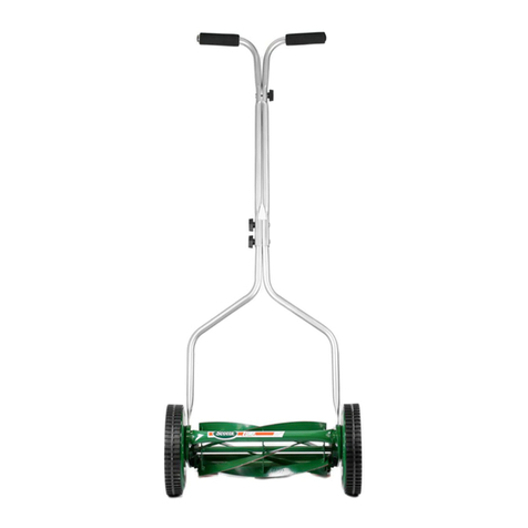
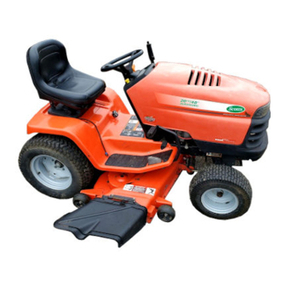
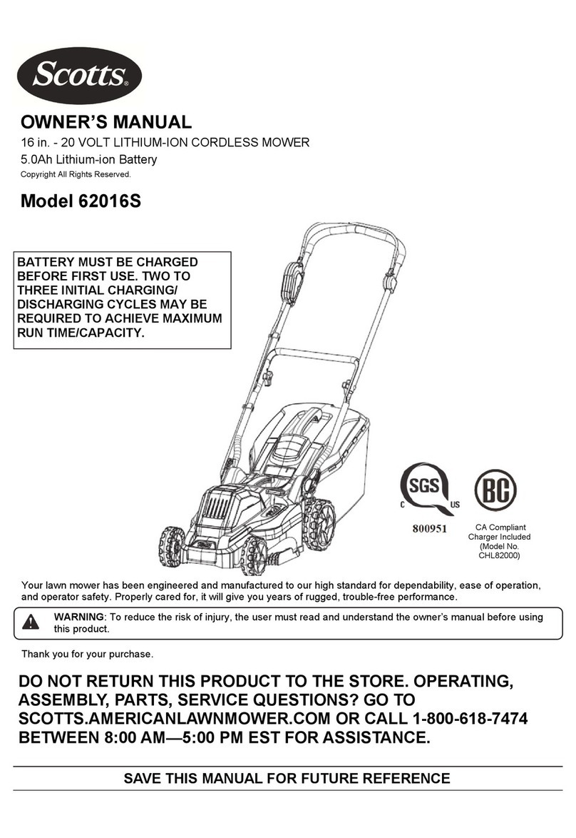
Scotts Turf Master C4013-050 User manual

ALL
WHEEL
STEER
Model
C4013·050
12.Shp/40"
PN
323308C
"Precision Engineering
by
the LawnCare Experts"
~
,f
Price
$5.00

TABLE
OF
CONTENTS
Page Page
WARRANTY .........................................................1
TABLE
OF
CONTENTS ........................................2 Change the Engine Oil .....................................14
Maintain the Air Filter .......................................15
INTERNATIONAL SYMBOLS ...............................2 Maintain the Fuel Filter ....................................15
SAFETY RULES ...................................................3
OWNER'S INFORMATION ...................................4
ASSEMBLE YOUR TRACTOR ..........................4-6
Contents
of
Shipping Carton .............................
.4
You Will Need These Tools ...............................4
Parts Bag ...........................................................4
Spark Plug Maintenance ..................................15
Maintain the Battery ....................................15,16
Remove the Battery ............................:............16
Install the Battery .......................................16,
17
Replace the Tractor Drive Belt .........................18
Remove the Mower Deck.................................19
Activate the Battery ............................................5
Install the Steering Wheel ..................................5
Install the Seat ...................................................6
Replace the Blade Drive Belt ...........................19
Replace the Mower Blades ..............................20
ADJUST YOUR TRACTOR ...........................21-30
Check Oil and Put
in
Gas...................................6
Check the Tires and Fasteners ..........................6 Read These Hints Before Adjusting Your
Tractor .............................................................
21
KNOW YOUR TRACTOR CONTROLS AND
INDICATORS.....................................................7-9
OPERATE YOUR TRACTOR ........................10-12
Learn to Start and Stop ....................................10
Before Starting .................................................10
Start the Engine and Mower Blades .................10
Stop the Mower Blades and Engine .................
11
Your First Use ..................................................
11
The All-Wheel Steer Feature............................
11
Use YourTractor Safely ...................................12
Keep Your Tractor Clean .................................12
Mowing Hints ...................................................12
Adjust the Tractor Clutch .................................22
Adjust the Transmission Control Lever ............
23
Adjust the Tractor Brake ..................................24
Adjust the Mower Deck Height.........................25
Adjust the Mower Deck Level ......................26,27
Adjust the Blade Drive Belt ..............................28
Adjust the Blade Brake ....................................29
Adjust the Carburetor.......................................29
Adjust the Steering Gear..................................30
Adjust the Seat.................................................30
TROUBLESHOOTING GUIDE ......................31-33
STORAGE ..........................................................34
MAINTAIN YOUR TRACTOR ........................13-20 TRACTOR REPAIR PARTS ..........................35-50
Maintenance Check List...................................13 ACCESSORIES ..................................................
51
Lubrication .......................................................14
Lubrication Chart..............................................14 DISTRIBUTORS LIST.........................................52
INTERNATIONAL SYMBOLS -
These symbols may appear
on
your unit or
in
literature supplied with the product. Learn and understand their meaning.
ENGINE
START
ENGINE
START
NEUTRAL
N
MOWER
HEIGHT
,-~··
ENGINE
RUN
ENGINE
START
FORWARD
•
I
LO'IVER
ENGINE
OFF
ENGINE
RUN
REVERSE
I
•
RAISE
t
-
OFF
ON
FAST SLOW CHOKE IGNITION
0 I
~
--
·1\1
ENGINE OIL FUEL BATTERY LIGHTS HOUR ALL-
METER SYSTEMS-GO
OFF PRESSURE
CLUTCH BRAKE PARKING PTO PTO MOWER BLADE
BRAKE ENGAGED DISENGAGED CLUTCH
CO)®
~_.......,~
~e
IGNITION
ARROW INCREASE . DECREASE CAUTION KEY
11 +
._..,.,.._
•
Photographs and illustrations
in
this manual may not show your model but are for reference. They are based on the
latest information available at time of publication.
2

SAFETY RULES
THESE INSTRUCTIONS ARE FOR YOUR PROTECTION. PLEASE READ THEM CAREFULLY.
IMPORTANT
THIS CUTTING MACHINE
IS
CAPABLE
OF AMPUTATING HANDS AND FEET AND THROWING OBJECTS. FAILURE TO OBSERVE THE
FOLLOWING
SAFETY
INSTRUCTIONS COULD RESULT IN SERIOUS INJURY OR DEATH.
I.
GENERAL
OPERATION:
• Know controls and
how
to stop quickly.
• Read, understand, and follow all instructions
in
the manual and
on the machine before starting.
•
Only
allow
responsible
adults,
who
are
familiar
with
instructions, to operate the machine.
• Wear
safety
glasses
or
eye
shields
when
assembling
or
operating the machine.
• Do
not
operate
machine
when
barefooted.
Always
wear
substantial footwear, preferably steel-toed shoes.
• Do
not
wear
loose
fitting
clothing
that
could
get
caught
in
moving parts.
• Clear the area
of
objects such as rocks, toys, wire, etc., which
could be picked
up
and thrown by the blade(s).
• Be sure the area is clear
of
other people before mowing. Stop
machine
if
anyone enters the area.
• Never carry passengers.
• Do
not
mow
In reverse unless absolutely necessary. Always
look down and behind before and while backing.
• Be aware
of
the mower discharge direction and do
not
point
it
at
anyone. Do
not
operate the mower
without
either the entire
grass catcher or the guard in place.
• Slow down before turning.
• Never leave a running machine unattended. Always turn
off
blades, set parking brake, stop engine, and remove keys before
dismounting. .
• Turn
off
blade(s) when
not
mowing.
•
Stop
engine
before
removing
grass
catcher
or
unclogging
chute.
• Mow
only
In daylight
or
good artificial light.
•
Do
not
operate the machinewhile under the influence
of
alcohol
or
drugs.
• Watch
for
traffic when operating near
or
crossing roadways.
• Use care when mowing around a fixed object to prevent the
blade(s) from striking it. Never deliberately run over anyforeign
object.
• Use extra care when loading or unloading the machine into a
trailer or truck.
• Use care when pulling loads
or
using heavy equipment.
a.
Use
only
approved drawbar hitch points.
b.
Limit
loads to those that you can safely control.
c.
Do
not
turn sharply.
Use
care when backing.
d. Use counterweight(s), wheel
weight
or
tire chains when
suggested
in
attachment(s) instructions.
II.
SLOPE
OPERATION:
Slopes are a
major
factor
related
to
loss-of-control
and
tip-over
accidents,
which
can
result
in severe
injury
or death.
All
slopes
require extra caution.
If
you cannot back
up
the slope
or
if
you feel
uneasy on it,
do
not
mow it. ·
DO
•
Uow
up
and down slopes,
not
across.
• Remove obstacles such as rocks, tree limbs, etc.
•
Watch
for
holes, ruts,
or
bumps. Uneven terrain could overturn
the
machine. Tall grass can hide obstacles.
• Use
slow
speed. Choose a low gear so that you will
not
have to
stop
or
shift
while on the slope.
•
Follow
the
manufacturer's recommendations for wheel weights
or
~ights
to
improve stability.
•
Use
alia
care
with
grass catchers or other attachments. These
can
ct.nge
the
slability
of
the machine.
• Keep
..
..,wement
on
the slopes
slow
and gradual. Do
not
llllllllesudden
changes
in
speed or direction.
•
AwoidSIIrtilgor
stDpping on a slope.
If
tires lose traction, turn
off
the~)
..t
proceed slowly straightdown the slope.
DONCJT
•
Do..,
...
-
slapes
Wlless necessary, and
_then
slowly and
graduiiiJ
......._
il
possible.
• Do
not-
-
*op-offs,
ditches
or
embankments.
The
mower could suddenly turn over
if
a wheel
is
over the edge
of
a
cliff
or
ditch, or
if
an edge caves in.
• Do
not
mow
on
wet
grass.
Reduced
traction
could
cause
sliding.
•
Do
not
try to stabilize the machine by putting your
foot
on the
ground.
•
Do
not
use grass catcher on steep slopes.
Ill. CHILDREN:
Tragic accidents can
occur
if
the operator is
not
alertto the presence
of
children.
Children are often attracted
to
the
machine
and the
mowing activity. Never assume
that
children will remain where you
last saw them.
• Keep
children
out
of
the
mowing
area and under the watchful
care
of
another responsible adult.
• Be alert and turn machine
off
if
children enter the area.
•
Before
and when
backing,
look
behind
and
down
tor
small
children.
• Never carry children. They may fall
off
and be seriously injured
or
interfere with safe machine operation.
• Never allow children
to
operate the machine.
• Use extra care when approaching
blind
corners, shrubs, trees,
or other objects that may obscure vision.
IV. SERVICE:
• Use extra care in handling gasoline and other fuels. They are
flammable and vapors are explosive.
a.
Use only
an
approved container.
b. Never remove gas cap
or
add fuel
with
the engine running.
Allow
engine
to
cool before refueling.
Do
not
smoke.
c. Never refuel the machine Indoors.
d. Never
store
the machine
or
fuel container Inside where
there
is
an
open flame,
such
as In a water heater.
•
Check
fuel
supply
before
each
use
allowing
space
for
expansion
as
the
heat
of
the
engine
and/or
sun
can cause
gasoline to expand and overflow the tank.
• Use extra care when handling battery acid. Acid contact with
skin
may
cause
severe
burns.
Eye
contact
may
cause
blindness. ·
• Use extra care when
servicing
the
battery. Explosive:
gas
is
produced
in
the
battery.
Do
not
service
the
battery
while
smoking
or
near an open spark or flame. This may cause the
battery to explode causing serious injury.
• Never run a
machine
inside
a
closed
area.
Exhaust
fumes
contain
CARBON MONOXIDE, an ODORLESS and DEADLY
GAS.
• Keep
nuts
and bolts, especially blade attachment bolts,
tight
and keep equipment
in
good condition.
•
Never
tamper
with
safety
devices.
Check
their
operation
regularly. ·
• Do
not
change
the
engine
governor
settings
or overspeed
engine.
• Reduce
fire
hazards. Keep machine free
of
grass, leaves,
or
other
debris
build-up.
Clean
up
oil
or
fuel
spillage.
Allow
machine
to
cool before storing.
• Stop and inspectthe equipment
if
you
strike an object. Repair,
if
necessary, before restarting.
• Never make adjustments
or
repairs with the engine running.
• Grass catcher components are subject
to
wear, damage, and
deterioration,
which
could
expose
moving
parts
or
allow
objects
to
be
thrown.
Frequently
check
components
and
replace
with
manufacturer's
recommended
parts,
when
necessary.
• Mower blade(s) are sharp and can cut. Wrap the blade(s) or
wear gloves, and use extra caution when servicing them.
•
Check
brake
operation
frequently.
Adjust
and
service
as
required.
LOOK
FORDE
SYIIBOL
TO
POINT OUT IMPORTANT SAFETY PRECAUTIONS. IT MEANS-ATTENTION!!! I
BECOMEALERT!!! YOUR SAFETY IS INVOLVED.
3
OWNER'SINFORMATION
Record thefollowing information about your unit so that you will
be
able to provide it
in
case of loss
or
theft.
MODEL NUMBER:
DODO
-DODO
(Enter complete 8 digit number from model plate on unit)
PURCHASE DATE: -
I-
I -CODE NO.:
----
SERIAL NO.:
------
DEALER'S NAME AND ADDRESS:
---------------------
CITY: STATE:
------
TELEPHONE:
-------
A DANGER
This
tractor
can bedangerous
if
usedcarelessly. Read
the
Owner'sManual
thoroughly
beforeoperating
thetractor. Alwayswearsafetyglasses
or
eyeshieldswhileassembling
or
operating
the
tractor. Do Not
carry passengers at anytime. Keep hands, feet, hairand loose
clothing
away from
the
dischargearea,
underside
of
the
mower
deck
or
any
moving
partswhiletheengine is running. Do Not allowchildren
or
young teenagers
to
operate
or
be near
the
tractor
while
it
is
operating. Reduce engine
to
idle when
tractor
is
not
moving. If
tractor
is
to
remain stopped
for
morethan 2 minutes,
stop
the
engine.
ASSEMBLE
YOUR TRACTOR
NOTE
References
to the
right
side
and
left side ofthis
tractor
are
as
you
are
seated
in
the operator's
seat,
facing forward.
CONTENTS
OF
SHIPPING CARTON
1 - Tractor
(with
40
inch
Mower
Deck)
1 - Owner's
Manual
1 -
Engine
Manual
1 -
Steering
Wheel
1 -
Seat
1 - Battery
Acid
Pack
1 -
Bag
of
Assembly
Parts
Containing:
1 - 1/4 x 2
inch
Spring
Pin
(Steering
Wheel)
4 - 11/32
inch
Flatwashers (Seat
Assembly)
4 -
5116
inch
Split Lockwashers (Seat Assembly)
4-
5116-18 x 3/4
inch
Hex
Head
Screws
(Seat
Assembly)
YOU
WILL
NEED THESE TOOLS
2-
1/2
inch
Wrenches
(or adjustable
wrenches).
2-
7116
inch
Wrenches (or adjustable wrenches).
1 -
Pliers
1 -
Small
Phillips Screwdriver
with
a
1/4
inch
shank
1-
Hammer
PARTS
BAG
@©
4-11/32
Inch
4-
5/161nch
Flatwashers SpiH Lockwashers
4-
5/16 x 3/4 Inch
HexHead Screws
4
ASSEMBLY TORQUE REQUIREMENTS -
FOR ALL
NUT
& BOLT, STEEL
TO
STEEL APPLICATIONS, FOOT-LBS
Note 1 Note 1 Note 1
BOLT 0 Q @
DIA.
INCHES
GR2
GRS
GR8
1/4 5-6 9-10 12-14
5/16 12-13
19-21
27-30
318
21-24 33-37 45-50
Notes:
1.
Head
identification
for
each grade.
2.
Reduce
thetorque
by
30%
when
installing into
aluminumparts.
3.
Reduce
torque by50%
when
threading into
non-extruded
sheet
metal parts.
I 1 -114 x 2 Inch Spring Pin
2-
lgnHion Keys

ASSEMBLE
YOUR TRACTOR
UNPACK SHIPPING CARTON
1. Remove the wooden top frame from the carton.
2. Remove parts packed separately
in
the carton,
including the seat, steering wheel battery acid and
hardware bag.
3. Cut down all four corners of the carton and
lay
down side pieces flat.
4. Remove packing material from around tractor.
5.
Carefully cut front and rear wire ties holding
tractor to skid.
6. Raise mower deck to high cutting position.
6. Be sure parking brake
is
released and shift control
lever is
in
neutral before rolling tractor off skid. NOTE:
You
may
need assistance
in
moving
tractor
off
skid. DO NOT lift
or
pull
tractor
by
the
hood
or
fender.
ACTIVATE THE BATTERY
DANGER
Lead
acid
batteries generate explosive gases.
Keep
sparks,
flame
and
smoking
materials
away
from
batteries.
Always
wear eye
protec·
tion
when
around
batteries.
1.
Remove the battery from the tractor (see Remove
the
Battery paragraph
in
the Maintenance section of
this manual) and remove the vent caps from all cells.
2.
Fill each battery cell to the indicator ring with
electrolyte battery acid. (Follow
the
instructions
out-
lined
on
the
electrolyte package).
DANGER
Handle
electrolyte
with
care. It
is
an
acid
and
poison.
Always
wear
eye shields,
and
protect
skin
when
handing
acid
or
battery.
POISON·CAUSESSEVERE BURNS
Containssulfuricacid.
Avoid
contact
with
skin,
eyes
or
clothing.
To
prevent accidents, neutralizeexcess
acid
with
baking
soda
and rinse
empty
container
with water. ANTIDOTE:
EXTERNAL-
Flush
with
water.
INTERNAL-
Drink
large
quantities
of
water
or
milk.
Folow
with
milk
of
magnesia, beaten
eggs
or
vegetable
oil.
Call
physician
immediately.
EYES·
Rush
with
water
for
15
minutes
and
get
prompt
medical
attention.
KEEP OUTOFTHE REACH
OF
CHILDREN
3.
Reinstall battery (see
Install
the
Battery
para-
graph in the
Maintenance
section of this manual).
NOTE: Before placing the battery into the tractor, the
battery should be charged at 6 amps for 1 hour. While
the battery is charging on a battery charger, complete
the Assembly section.
NOTE
The charge indicator light will glow if the battery is
not charged to 75% of its capacity.
INSTALLTHE STEERING WHEEL
1. Position the front wheels straight forward.
2.
Place the steering wheel on the steering shaft
(Figure 1).
NOTE
Make sure the cross-members on the steering
wheel are pointing downward.
3. Push the steering wheel down firmly.
4. Align the cross holes in the steering wheel with
the holes in the steering shaft.
NOTE:
Use
a small Phillips screwdriver (with a 1/4
inch shank) to align the holes.
STEERING
WHEEL
SPRING
PIN
./

ASSEMBLE
YOUR TRACTOR
INSTALLTHE SEAT
1.
Raise the seat channels (Figure 2) and attach the
seat to the seat channels with four 5/16 x 3/4 inch
screws, four 5/16 inch split lockwashers and four 11/32
inch flatwashers (found
in
parts bag). To adjustthe seat
see the
Adjust
TheSeatparagraph
in
the
Adjust
Your
Tractor section
of
this manual.
2.
Connect the wire harness to the seat switch
(Figure2). NOTE: Ifthe seat switch is not connectedto
the wire harness, the engine will stop when the mower
clutch leveris placed in the ENGAGE (DOWN) position
or the clutch-brake pedal
is
in
the ENGAGE (UP) posi-
tion.
lji·@fW
SEAT
CHECK OIL AND PUT IN GAS
NOTE
Be suretheenginecrankcase
is
full
of
oil
before
trying
to
start
the
engine.
1.
Place the tractor sothat the engine is level.
2.
Open the hood.
3.
Remove the engine oil fill cap/dipstick (Figure 3)
and checkoil level. Add oil if necessarySeetheEngine
Operation
and
Maintenance manual for the proper
procedure and engine oil recommendations. Do not
overfilL
4.
Reinstall the oil fill cap and tighten it securely.
5.
Be sure the spark plug wire(s) is attached to the
spark plug(s).
6
6.
Fill the gas tank
(Figure
3). Use clean, fresh,
unleaded gasoline with a minimum octane rating of 77.
Do
not
mix
oil
with
gasoline. Be certain the container
is clean and free from rust or other foreign particles.
Neveruse gasoline that may be stale from long periods
(over 30 days) of storage.
DANGER
Never
fill
the
gas
tank
while
the
engine
is
run-
ning
or
is
hot.
Immediately
wipe
off
any
spilled
gasoline before
attempting
to
start
the
engine.
lj!.!lifji
GASCAP
-
OIL FILLCAP/
DIPSTICK
CHECK THE TIRES AND FASTENERS
1.
Check the air pressure
in
the tires. The correct air
pressure
(1
0to 141bs) may be printed onthe sidewall of
each tire. Ensure that both front and rear tires are in-
flated properly.
2.
Check all bolts on the wheels to be sure none are
loose.

KNOW
YOUR TRACTOR CONTROLS &INDICATORS
Get to know yourtractor and its controls and indicators.
Be sure you (or any other operator) have read and
understand the Safety Rules listed on page 2 of this
manual.
DANGER
Do
not
operate
your
tractor
without
a
chute
de-
flector in place. The
tractor
can be dangerous
to
operate
if
misused. On slopes, be very
cautious
and
avoid
sharp
turns
to
prevent
tipping
or
loss
of
control.
NEVER
carry
passengers.
The controls and indicators and their functions are
as
follows:
•
Throttle
Control
and
Choke Lever (Figure 4A) -
Controls the engine and blade speeds and chokes
the engine for cold starts. For best mowing, always
run
the engine
at
fast speed.
e
Ignition
Switch (Figure 4A) -Starts and stops the
engine. Turn the key all the way right to start the
engine. When you release the key (after starting the
engine) it will return to the running position. To stop
the
engine, turn
the
key all
the
way to the left.
Remove the key to lock the ignition.
•
Headlight
Switch
(Figure
4A) -Turns the head-
lights on oroff. With the engine running, push the
ON
end of the switch to turn the headlights on.
To
turn
the headlights off, push the OFF end ofthe switch.
NOTE
Use the headlights only with the engine running. If
you leave the headlights on (with the engine not
running) you may need tochargethe battery before
re-starting the engine.
• Battery Indicator(Figure 4A -Ifthis indicator lights
up, your engine
is
not sending enough voltage to the
battery or the battery is not properly charged.
Turn off your headlights and run the engine at full
throttle to charge the battery.
• Fuel
Indicator
(Figure
4A-
If
this indicatorlights up,
you
are low
on
fuel. Stop the tractor and add fuel to
the gas tank.
• Oil Pressure
Indicator
(Figure 4A,
if
so
equipped)
-
If
this indicator lights up, you do not have enough oil
pressure to properly operate the engine. Stop imme-
diately and check the oil level.
•
"All
Systems
Go"
Indicator
(Figure
4A)-
Indicator
lights if the wrong starting procedure was used.
Check one or both:
1.
Your
clutch-brake
pedal
may
not be fully
pressed down.
2.
The
mower
clutch
lever
may not be in the
DISENGAGE (UP) position.
•
Hour
Meter (Figure 4A),
if
so
equipped
-Counts
the total
number
of
hours
the
tractor
has been
operated. Use this meter with the
Maintenance
Check
List
(page 13) to schedule maintenance for
your tractor.
OIL PRESSURE
INDICATOR
(If
so
equipped)
BATTERY
"ALL
SYSTEMS
GO"
INDICATOR
HEADLIGHT
dii!IJf·l
PARKING BRAKE
KNOB

·lL-
__
K_N_O_W_~_O_U_R_7i_'8_~_C_1i_O_R_C_O_N_7i_'R_O_L_S_&_I_ND_I_C_~_1i_OR_S
__
___,
• Parking Brake Knob (Figure4A) -
Locks
the clutch-
brake pedal
in
the brake position.
To
operate the
parking brake:
1.
Press
down
the clutch-brake
pedal
fully,
engaging
the brake.
2.
Lift
and
pull the parking brake
knob
and
hold
it.
3.
Remove
your
foot
from
the clutch-brake pedal
(the
pedal
should
remain
down).
4.
Release
the parking brake
knob.
To
release the parking
brake,
press
the clutch-brake
pedal
(gravity
will
release
the
parking
brake).
NOTE
Check
the position ofthe transmission control lever
and
know
what
you
want
to
do
before
you
release
the
clutch-brake.
• Transmission Control Lever (Figure 4B) -
Selects
1 of 6 forward ground speed ranges, 1 reverse
ground
speed
range
and
neutral.
NOTE
The
transmission control lever
is
connected to the
clutch
assembly.
You
don't
need
to
use
the clutch
pedal
when
shifting
forward
gears.
No.
1 range
is
the
slowest
forward
speed,
used
for
traveling
up
or
down
steep
hills
or
snow
removal.
! !
No.
2 range
is
used
for
cutting tall or
heavy
grass.
No.
3 range
is
used
for
average
mowing
conditions.
No.
4and 5 ranges
are
used
for very light
mowing.
No. 6 range should
be
used for transporting the
mower
only.
CAUTION
Come
to
a
full
stop
before
changing
the
direction ofmotion.
• Clutch-Brake Pedal (Figure
4C)
-
Use
the clutch-
brake
pedal
(all the
way
down)
to stop or park your
tractor. Always lockthe clutch-brake pedal
in
the
parking brake position (all the way down)before
leaving thetractor.
NOTE
You
don't
need
to usethe clutch-brake pedal
when
changing
forward
speed
ranges.
8
TRANSMISSION
CONTROL LEVER
SHIFT
POSITIONS
~
~----=--
------·

KNOW
YOUR TRACTOR CONTROLS& INDICATORS
•
Cutting
Height
Adjustment
Lever
(Figure
4D) -
Changesthe height ofthecut
to
one
of
five positions.
The bottom position
of
the lever is the lowest cutting
height and
the top
position is
the
highest cutting
height. Other positions change the height
of
the cut
approximately 1/2inch each.
1.
Grasp
the
lever
with
your
left hand and pull
upward to raisethe mowerdeck. You will hear a
"click"
as
the
lever
goes
to
the
next
height
position.
2.
Grasp
the
lever
with
your
left hand and pull
upward slightly. Press the button on end
of
the
lever
with
your
thumb
to
release
the
height
adjustment
lever
latch and lower
the
mower
deck
to
the height you want. Release the latch
button to let the lever latch
in
place.
•
Mower
Clutch
Lever
(Figure
4D)
-
Gives
or
removes powerto the mower deckblades.
To
start
the
mower blades, move the mower clutch
lever slowly (Never
"snap"
the
lever) down to the
ENGAGEposition.
NOTE
Move
the
mower
clutch
lever
to
the
ENGAGE
(DOWN) position only when you are ready to cut
grass, and when the engine is running at full speed
(this prevents excessive strain on the blade drive
belt).
To
stop the mower blades, move the mower clutch
lever slowly up to the DISENGAGE position. With
the
mower
clutch lever in
the
DISENGAGE
(UP)
position, blades should stop in a safe period
of
time.
Keep
the
mower
clutch lever in
the
DISENGAGE
(UP) position until you are ready to cut grass; and
when using yourtractorfor yard jobs such
as
pulling
a roller, seeder, sweeper
or
otheraccessories.
NOTE
The
mower
clutch
lever
must
always
be
in
the
full
DISENGAGE
(UP)
position
to
start
the
engine.
Never
place
the
lever
in
the
ENGAGE
(DOWN)
position
until
the
engine
is
warmed
up
and
JOU
are
on
the
seat,
ready
to
start
mowing.
AllrafS...,.
the
lever
to
the
DISENGAGE
(UP)
posllaa
belal'e
dismounting
from
the
tractor.
A DANGER A
The
blades
..
not
stop
immediately.
Keep
hands
..:I
feellrala
under
mower
deck
and
awayfnllll
..
'•
._ge
chute.
CUTllNG~
ADJUSTMENTLEVER
HIGH
CUT
POSITION
(UP)
LOW
CUT
POSITION
(DOWN)~
""'~
NOTE
Your unit is equipped with a seat switch. The en-
gine will stop
if
the operator is not firmly seated in
the operator's seat when the mower clutch lever is
in
the
ENGAGE
(DOWN) position
or
the
clutch-
brake
pedal
is in
the
ENGAGE
(UP)
position.
Leaning forward
or
to
one
side on the seat may
cause the engine to stop.

I ,
'I
'
' '
OPERATE YOUR TRACTOR
LEARN TO START AND STOP
Before
Starting
NOTE
Be sure
thP.
enginecrankcase is full ofoil beforetry-
ing
to
start the engine. See the
Engine
Operating
and
Maintenance manual.
Always check the oil level before starting the engine.
1.
Remove oil fill cap and wipe the dipstick clean.
2.
Screw the oil fill cap/dipstick firmly but slowly until
the cap is fully tightened.
3. Remove the dipstick and check oil level. It should
fall between the ADD and FULL lines. Iftheoil level is at
orbelowthe ADD line, you need to add oil. Consult your
engine manual for more details.
Do
not
overfill.
IMPORTANT
Your
tractor
has
two
normally-open
lockout
switches between the ignition key switch and the
starter solenoid.
When
starting
the
tractor,
the
clutch-brake pedal must befully pressed down and
the mowerclutch levermust be in full DISENGAGE
(UP) position. The engine will not turn over unless
these conditions are met and the
"All
Systems
Go"
indicatorwill light up.
NOTE
Your unit is equipped with a seat switch. The en-
gine will stop if the operator is not firmly seated in
the operator's seat when the mower clutch lever is
in the
ENGAGE
(DOWN) position
or
the clutch-
brake
pedal
is
in
the
ENGAGE
(UP)
position.
Leaning forward
or
to
one side on
the
seat may
cause the engine to stop.
Start
the
Engine
and
Mower Blades
1.
Check to make sure the fuel tank contains clean,
fresh gasoline, and the engine crankcase is full ofoil.
2.
Press and
hold
the
clutch-brake
pedal
all
the
way down.
PlaC£'
the transmission control lever in the
neutralposition.
3.
Place the mowerclutch lever
to
the DISENGAGE
(UP) position.
4.
Move the throttle control and choke lever forward
to the START position on a cold engine,
FAST
(MOW)
position on a warm engine.
5.
Turn the ignition key clockwise to start.
6.
Afterthe engine starts, move the throttle control
lever
to
the speed you want.
7.
Move the mower clutch lever
to
the ENGAGE
(DOWN) position.
If
the
engine
cranks
but
fails
to
start,
try
the
following:
1.
Check to make sure the fuel tank contains clean,
fresh gasoline.
2.
Check
to
make surethe spark plug(s) is tightened
securely into the engine and the spark plug wire(s)
is
attached
to
sparkplug(s).
If
engine
does
not
crank,
check
the
following:
1.
Be sure the clutch-brake pedal is fully depressed
and the mower clutch le,·er is in the DISENGAGE (UP)
position. If not, your
"A.I
Systems
Go"
indicator will
light up.
2.
Be
sure
the
battery
has
been
serviced
and
charged.
3. Check the fuse in the red wire near the solenoid
(found inthe battery compartment).
DANGER
Never
run
the
engine
indoors
or
in
enclosed,
poorly
ventilated
areas.
Engine
exhaust
con-
tains
CARBON MONOXIDE,
an
ODORLESS
and
DEADLYGAS.
Keep
hands,
feet,
hair
and
loose
clothing
away
from
any
moving
parts
on
the
engine
or
the
tractor.
WARNING-
Temperature
of
the
muffler
and
nearby
areas
may
exceed
150° F.
Avoid
these
areas.

OPERATE YOUR TRACTOR
Stopthe Mower Blades and Engine
DANGER
The blades
on
your
mower
will
not
stop
immedi·
ately. Keep
your
hands
and feet
from
under
the
mower
and away
from
the
discharge
chute.
To mow safely, you also need to know how to stop the
mower blades and engine.
To
stop
the
mower
blades:
1.
Move the mower clutch lever to the DISENGAGE
(UP) position.
To
stop
the
engine:
1.
Move throttle control and choke leverbackward to
SLOW position before turning off ignition to reduce
muffler "pop." NOTE: Failure
to
do
this
can resuH
in
engine
and
exhaust
system
damage.
2.
Turn the ignition key to OFF.
3. Lowerthe mower deck.
4. Remove the ignition key.
ALWAYS
DISMOUNT
TOTHE LEFT SIDE.
CAUTION
TO AVOID SERIOUS INJURY OR DEATH
Read Owner's Manual.
Know
location
&
function
of
all
controls.
Keep
guards,
safety
shields,
and
switches
in
place
and
working.
Remove
obJects
that
could
be
thrown
by
blade(s).
Do
not
mow
when
children
&
others
are around.
Nevercarry
children
or
passengers.
Look
down
and
behind
before
and
while
backing.
Do
not
mow
where
machine
could
tip
or
slip.
If
machine
stops
going
uphill,
disengage
blacle(s) and
back
down
slowly.
Remove key
when
leaving machine.
Avoid
sudden
turns.
Go•
iBI
down
slopes,
not
across.
Yo•
FirstUse
1.
After
the
engine
has
warmed-up,
move
the
transnissiaa
UA.U
le¥ertothe gearyou want.
2.
Slowly
•
eln
se
dulch-brake
pedal
to
start
the
tractormoWig.
3.
Until you
get
the
feel
of
the
tractor, keep
the
throttle control and choke lever in the SLOWposition.
4. With the mower blades stopped, learn to start,
stop, and change directions.
5.
The rear wheels of your tractor are driven by a
transaxle similar
to
a differential on a car. If a wheel
slips
or
starts spinning, shift yourweighttothat wheel to
increase pulling power.
The All-Wheel Steer Feature
Because both
the
front
and rear
wheels
turn,
the
all-wheel steer tractor is very maneuverable. If the
tractor becomes wedged against a wall, fence orother
obstruction, dothe following:
1. Move transmision control leverto No. 1position.
2.
Turn the steering wheel
slightly
away from the
obstruction.
NOTE
Ifyou turn sharply (move steering wheel more than
7°),
the
rear
wheels
will
turn
in
the
opposite
direction of the front wheels (turning into the object
you are turning away from).
3. You can reverse the tractor to back out
of
dead
ends.
CAUTION
Before
backing
up,
stop
the
mower
blades
(move
the
mower
clutch
lever
to
the
DISEN-
GAGE
(UP)
position).
Be
sure
the
tractor
is
completely
stopped
before
shifting
into
re-
verse.
Before
backing
up,
carefully
check
the
area
behind
you
for
children,
pets
and
other
obstructions.
DANGER
Do
Not
operate
this
tractor
without
a chute de-
flector
in
place. A
tractor
can
be
dangerous
to
operate
if
misused.
On
slopes,
be
very
cautious
and
avoid
sharp
turns
to
prevent
tipping
or
loss
of
control.
NEVER
carry
passengers.

OPERATE YOUR TRACTOR
USE YOUR TRACTOR SAFELY
Your tractor may throw objects up
into your eyes, and damage them
severely. Always wearsafety glasses
or
eye
shields
while
using
your
mower. We recommend standard
safety
glasses
or
a
Wide
Vision
Safety Mask overspectacles.
WARNING
This
tractor
is
equipped
with
an internal
com-
bustion
engine
and
should
not
be
used
on
or
near
any
unimproved
forest-covered,
brush-
covered
or
grass-covered
land
unless
the
engine's
exhaust
system
is
equipped
with
a
spark arrestermeeting applicable local
or
state
laws
(if
any).
If
a
spark
arrester
is
used,
it
shouldbe maintained
in
effective
working
order
by
the
operator.
See
your
authorized
Engine
Service
Dealer
for
the
proper
spark
arrester
muffler
for
the
engine
on
your
tractor.
Remember these rules when
you
(or others) use your
tractor.
e Never
run
into trees, curbs, etc.
• Run your tractor at slow speeds until you get to
know the operation ofthe tractor.
• Avoid sharp turns
at
high speed and any uphill or
downhill turns.
• Operate
your
tractor
carefully. Be especially
cautious
on
hills.
• When riding down hills
or
inclines, put the shift
control lever in low gear and do not press the
clutch-brake pedal. This allows the engine
to
control your speed. Use the clutch-brake pedal
for fast stops on hills.
12
KEEP YOUR TRACTOR CLEAN
e Remove cut grass from yourmower after each
mowing.
• Remove the ignition key and scrape offgrass witt
a putty knife ora similartool.
e Remove the mowerdeck for easier cleaning. See
the Remove The
Mower
Deck instructions
in
the
Maintain YourMowersection ofthis manual.
e Remove dirt and debris from the engine area with
a brush
or
cloth.
MOWING HINTS
1.
Before you start mowing, be sure
you
have moved
thethrottle control and choke leverforward tothe FAST
(MOW) position for a warm engine or START position
for a cold engine.
You
control your ground speed with
the shift control lever.
2.
For heavy orcoarse grass, lower your speed.
3.
For light grass,
you
can increase your speed.
4. To avoid leaving unmowed strips when mowing
long
or
tendergrass, mow the lawn
in
a counter-
clockwise direction, overlapping the previous cut.
5.
When you stop your tractor on a grass surface,
place the throttle control and choke lever in the SLOW
position. If
you
are stopped for2 minutes ormore, turn
the engine off. The hot air used to cool the engine will
exhaust onto the grass causing dry (brown) spots
on
your lawn.
IMPORTANT: SANDY CONDITIONS WILL CAUSE
THE HIGH-LIFT BLADES ON YOUR UNIT TO WEAR
MORE FREQUENTLY. WHEN MOWING GRASS
IN
SANDY CONDITIONS, REPLACE THE HIGH-LIFT
BLADES WITH LOW-LIFT BLADES (305012). NOTE:
LOW-LIFT BLADES ARE NOT RECOMMENDED
FOR
BAGGING GRASS.

l
I
I'
MAINTAIN YOUR TRACTOR
The warranty on this tractor does not cover items that
have been subjected to operator abuse or negligence.
To receive full value from the warranty, you must main-
tain your tractor as instructed in this manual. The fol-
MAINTENANCE
CHECK LIST
BEFORE
STORAGE
BEGINNING
EACH
SEASON
EVERY
50
HOURS
EVERY
25
HOURS
FREQUENTLY
AFTER
EVERY
USE
BEFORE
EACH
USE
AFTER
FIRST
5
HOURS
Check Engine Oil Level •
Change Engine Oil • •
Check Battery Fluid • •
Clean
or
Replace Air Filter •
CheckSpark Plug(s)
CheckTire Pressure (10 to 141bs.)
Tighten all Loose Screws & Nuts • •
Inspectfor Worn/Damaged Parts •
Clean MowerDeck •
Clean Tractor •
Check Drive Belt Adjustment •
CheckTractor Brake Adjustment •
Check
Mower
Deck Belt Adjustment •
Lubricate Steering Shaft •
Lubricate Steering Sector
Gear
•
Lubricate Front Spindles •
Lubricate Front Wheel Bearings •
Lubricate Unkage & Pivot Points •
Lubricate UniversalJoints •
Lubricate DeckQuillAsseni>lies
•
•
13
lowing Maintenance
Check
List is supplied to assist
you to properly maintain yourtractor. This
is
acheck list
only. The adjustments referred to will be found
in
the
Adjust
Your
Tractor
section ofthis manual.
SERVICE RECORD
FILL IN DATES
OR
HOUR SHOWN ON
HOUR METER
AS YOU COMPLETE
REGULAR SERVICE
•
••
•
••
•
•
•

/
<.
MAINTAIN YOUR TRACTOR
LUBRICATION CHART
Orientationviewonly. Do Notstand on end.
~
USE
SAME OIL USED
IN
CRANKCASE
"91'
EVERY 25 HOURS OF OPERATION
USE
A GOOD GRADE OF
CUP
GREASE~
14
CAUTION
At
no
time
during
maintenance
or
adjustments
should
the
tractor
be
lifted
more
than
20
inches
from
a level
position
without
taking
the
follow-
ing
precautions:
1.
Remove
the
gasoline
from
the
tank
and
run
the
engine
until
the
carburetor
is
dry.
2.
Remove
the
battery
(see
REMOVE THE
BATTERY
paragraph
in
this
section).
3. Remove
the
oil
from
the
crankcase.
LUBRICATION
For lubrication frequency see the Maintenance
Che1
List. For lubrication points and type of
lubricant see
Lubrication
Chart.
CHANGE THE ENGINE OIL {Figure 5)
Change the engine (crankcase) oil afterthe first 5
hou
of
operation and every
25
hours thereafter. See
tl
Engine
Operating
and
Maintenancemanual for
rna
information. Checkthe oil levelbefore each use. Add
as required.
1.
Place a flat bottom, 2 quart container beneath
tl
oil drain plug •
NOTE
You may need
to
raise the left side
of
the tractor
(with blocks under the left wheels)
to
get proper
drainage.
2. Remove
the
011
drain plug
to
drain the oil.
NOTE
The oil fill cap/dipstick should
be
loosened to serve
as an airvent.
3. Replace the oil drain
pkJg.
4. Remove the oil
fiD
cap/dipstick and refill engi
(crankcase) with oil.
See
Engine
Operating
and
Mai
tenance manual forengineoil recommendations.
5.
Replacethe
011
fill cap/dipstick.

MAINTAIN YOUR TRACTOR
OIL DRAIN
PLUG
MAINTAIN THE AIR FILTER
The air filter should be cleaned or replaced after 25
hours of operation under normal operating conditions,
more often under dusty conditions. To clean the air fil-
ter, follow the instructions in the
Engine
Operating and
Maintenancemanual.
CAUTION
Never
run
the
engine
without
the
air
filter
in-
stalled. A
defective
air
filter
can
result
in
loss
of
engine
power
and
can create
excessive
wear
or
damage
to
engine
components
if
dirt
or
dust
is
permitted
to
enter
engine
through
the
carbure-
tor.
Replace a
damaged
air
filter,
or
clean
one
that
is
clogged
with
dust
or
dirt
immediately.
MAINTAIN THE FUEL FILTER (Figure 6)
Check the in-line fuel filter at frequent intervals and re-
place before the screen becomes clogged with sedi-
ment
Make sure the replacemert is correctly installed
with
the IN markingtowardthe
tar*
and
theOUTmark-
ing toward the engine_ Check1he
lEI
SJSiem
c:orqJO-
nents {re(JJendy and
leplace
anr
padS
sluMI4j
.....
spots
oraacks..
~
AuELLINE
-TO
TANK
SPARK PLUG MAINTENANCE
Check the spark plug(s) periodically for excessive car-
bon and gap. See the
Engine
Operating
and Mainte-
nance
manual.
MAINTAIN THE BATTERY
DANGER
Lead
batteries
generate
explosive
gases. Keep
sparks,
flame
and
smoking
materials
away
from
batteries.
Always
wear
eye
protection
when
around
batteries.
Check the level of electrolyte in the battery once a
· month or after every 25 hours
of
use whichevercomes
first. If the electrolyte is below the indicator ring at the
top ofthe battery, remove the vent caps and add clean
water
to
each batterycell. Whenthe electrolyte istothe
indicator ring level, replace the vent caps.
NOTE
NEVER
ADD
ADDITIONAL
ELECTROLYTE TO
THE BATTERY. Do not add
water
past
the
level
ol
the
indiallor
ring.

MAINTAIN YOUR TRACTOR
Ifthe battery needs morethan 1
or
2 ounces
of
waterin
each cell per month
or
after every
25
hours
of
use
whichever comes first, the charging system may
be
malfunctioning.
Have
the
battery
and/or
electrical
system checked
by
a trained serviceman.
When
the
starter operates properly and
the
battery
connections are clean and tight but you have cranking
difficulty,
the
battery may not
be
fully charged. The
battery should be taken to a qualified service station
and tested.
If the engine will not start right away under normal
cranking speed, continued cranking will run down the
battery and may cause damage to the starter. Check
the ignition and fuel systems and correct any faults.
Keep the battery clean. If
the
top
is
dirty
or
greasy,
remove the battery (refer to the Remove
the
Battery
paragraph) and clean with a mild solution
of
baking
soda and water. Keep
the
vent
plugs
tightly
in
place
to
prevent
any
solution
from
entering
the
cells.
Al-
low the solution to work for a few minutes and remove
with clean water. Wipethe batterydry. Ifthe batteryter-
minals are corroded, clean with a wire brush and coat
the terminals with petroleum jelly. Refer to the
Install
The
Battery
paragraph
in
the
Maintain
Your
Tractor
section
of
this manual and reinstall the battery.
Propercare will lengthen battery life. When you need to
replace the battery, use a battery of the same size and
type for continued trouble-free service (see the Repair
Parts section ofthis manual).
. REMOVE THE BATTERY (Figure 7)
1.
Raise the seat and remove the battery hold-down
rod andthe battery hold-down bracket. Slidethebattery
to the rear.
2.
Disconnect the negative (black) battery cable and
tie back.
3.
Disconnect the positive (red) battery cable and tie
back.
DANGER
Always
disconnect
the
negative
(black)
cable
first.
Removing
the
positive
(red)
cable
first
can
result
in
sparks
if
the
wrench
touches
any
metal
surface. Be
sure
the
battery
hold-down
bracket
does
not
touch
the
battery
terminals
and
cause
a
spark.
16
4.
Lift the batteryout
of
thetractor.
To
install
the
battery,
refer
to
Install
The
Battery
paragraph in
Maintain
Your
Tractor
section
of
this
manual. 1
INSTALL THE BATTERY (Figure 7)
1. Raise the seat and place the battery back into the
tractor with the positive (+) terminal toward the right
rear
of
thetractor.
DANGER
Always
connect
the
positive
(red)
cable
first.
Connecting
the
negative
(black)
cable
first
can
result
in
sparks
if
the
wrench
touches
any
metal
-
surface.
Be
sure
the
battery
hold-down
bracket
does
not
touch
the
battery
terminals
and
cause_
a
spark.
2.
Attach
the
positive
(red)
battery
cable
to
the
positive(+) terminal on the battery with a 1/4 x 5/8 inch
hex head screw and a 1/4 inch keps nut.
NOTE
You will have to slide the rubber boot away from
the end
of
the positive (red) cable before installing
the cable. After installatiion, slide
the
rubber boot
overthe end
of
the red battery cable and the posi-
tive (+) terminal.

MAINTAIN YOUR TRACTOR
3. Attach the negative (black) battery cable
to
the
negative(-) terminal on the battery with a 1/4x 5/8 inch
hex head screw and a 1/4 inch keps nut. Slide the bat-
tery forward and to
the
right into the battery recess.
4.
Place the battery hold-down bracket through the
hole in the right hand side
of
the frame.
NOTE
Turn thebracket to the side, placethrough the hole
in the seat support and rotate upright.
NEGATIVE(-)
BATIERY
TERMINAL
HOLD-DOWN
ROD
5.
Place the hook-end
of
the
battery hold-down rod
through the slot in the main frame and hook into the
small hole besidethe battery.
6.
Place the threaded end
of
the battery hold-down
rod through the loop in the bracket and secure with the
plastic wingnut. Pliers may
be
needed to tighten the
plastic wing nut.
BLACKBATIERY
CABLE
,.;
HOLD-DOWN
BRACKET
1/4X 5/SINCH
HEXHEAD SCREW
POSITIVE(+)
BATIERY
TERMINAL

'~-------------M-~_IN_~_~_IN
__
YO_U_R
__
~_RA
__
C_TO_R
____________
~
When replacing the belts, to prevent damage to your
tractor, useonly
original
equipment
belts (see Repair
Parts section
of
this manual). NEVER USE A SUBSTI-
TUTE.
REPLACE THE TRACTOR DRIVE BELT
(Figure 8)
To replace the tractordrive belt follow the steps below:
1.
Remove the mower deck. (Refer to Remove The
MowerDeck paragraph.)
2.
Depress
the
clutch-brake
pedal
and
set
the
parking brake.
3.
Note position of idler belt guide. Loosen the belt
retainer on the clutching idler pulley and remove belt
from clutching idler pulley.
4.
Remove the belt from the engine pulley (roll the
belt off overthetop ofthe pulley).
5.
Remove the belt from the transaxle pulley and
replace with a new original equipment belt. Install the
new belt in reverse orderof removal.
Mj!.!l!ii:l
UPPER
ENGINE--~~~~'
PULLEY
BELTGUIDE
CLUTCHING
IDLER
PULLEY
TRANSAXLE
PULLEY
18
6.
Refer to
Adjust
Tractor
Clutch
paragraph (in the
Adjust
Your
Tractor
section of this manual) and adjust
the tractorclutch.
7.
Check the tractor brake adjustment. If you need to
adjust the brake, refer to the
Adjust
The
Tractor
Brake
paragraph
in
the
Adjust
Your
Tractor
section of this
manual.
NOTE
If the mower blade drive belt is to be replaced, do
so before reinstalling the mowerdeck assembly. .
LOWER
ENGINE
PULLEY
CLUTCHING
IDLER PULLEY
MOUNTING SCREW

MAINTAIN YOUR TRACTOR
REMOVE THE MOWER DECK (Figure 9)
1.
Put the height adjustment lever in its lowest cut
position.
2.
Remove the hairpin cotter from the mower deck
engagement rod and remove the clevis pin from the
engagement lever. Then remove the rod from the en-
gagement lever.
3.
Remove the hairpin cotter from the front and rear
lift assemblies.
4.
Remove the clevis pins.
5.
Remove the hairpin cotter from the mower deck
hitch rod and remove the hitch rod.
6.
Movethe mowerdeckforward. Then move the belt
guides away from the belt and remove the blade drive
belt from the lower engine pulley.
7.
Removethe mowerdeck byworking it out from the
right side ofthe mower.
NOTE
The mowerdeck removal will be easier ifthe tractor
wheels are turned tothe left, and the mowerdeck is
raised enough to allow the mower deck hitch to
slide out underthe right front wheel.
Installation
of
the
mower
deck
is
the
reverse
of
removal.
REPLACE THE BLADE DRIVE BELT
(Figure
9)
1. Referto the Remove The Mower Deck paragraph
and remove the mower deck.
2.
Note the position ofthe idler pulley belt retainer so
that you can reposition the retainer properly after the
new blade drivebelt is installed. Loosen the idler pulley.
3. Loosenthe mowerdeck beltguard enough
to
allow
the belt to be removed from the pulley.
4. Removethe old blade drive belt and replace
it
with
a new, original equipment belt.
5.
Retighten the belt guard.
6.
Adjust the belt retainer and retighten the idler
pulley.
7.
Refer to Remove
The
Mower
Deck
par;:~graph
and reinstall the mower deck assembly
in
the reverse
orderof removal.
8.
Refer to Adjust The Blade Drive Belt paragraph
(in the Adjust YourTractorsection ofthis manual) and
adjust the blade drive belt.
LIFT
ASSEMBLY
IDLER PULLEY
BELT RETAINER
MOWER
DECK
MOWERDECK CLUTCH SPRING
ENGAGEMENTROD

'
~
'
MAINTAIN YOUR TRACTOR
REPLACE THE MOWER BLADES
(Figure 10)
To
run
smoothly, the cutting blades should be sharp-
ened and well-balanced. Blades should have the cor-
rect
amount of "lift" to properly cut and discharge the
grass clippings. Lift
is
created by the bent tip edges of
the blade ends.
As
the cutting edges of the blades
wear, thebent tip edges also wear, decreasing blade lift
and
also decreasing cutting ability.
Resharpening the blades will not help this condition.
The blades should be replaced.
IMPORTANT
If you strike any solid unyielding object,
stop
the engine, disconnect
the
spark plug wire(s)
and inspect the blades at once. Check
to
make
sure
both
blade
mounting
screws aretight.
To remove the blades, proceed as follows:
1.
Referto the Remove The Mower Deck paragraph
and
remove the mowerdeck.
DANGER
DO
NOT handle
the
blades
with
bare hands.
Wear gloves
or
wrap the blade with newspaper
or
other
material while removing
or
installing
blade.
l§[.jijijl·l
INSET BENTTIP
EDGE
ld._~~,._
SPRING
WASHERS
~MOUNTING
SCREW
2.
Using a 9/16 inch wrench, remove the blade
mounting screws by turning the screws counter-
clockwise. Remove the spring washers and blades.
3.
Install the new blades with the bent tip edges
towards the top of the mower, and spring washers,
as
shown
in
inset.
NOTE
Severe
vibration
will
occur
if
you do not
reassemble the parts in proper order (see Repair
Parts section
of
this manual for proper order).
4.
Tighten the blade mounting screws securely.
Torque the blade mounting screws to between 30
and
35 foot pounds.
5.
Refer
to
the Remove The MowerDeckparagraph
and reinstall the mower deck assembly
in
the reverse
orderof removal.
SHARP EDGE
This manual suits for next models
1
Table of contents
Other Scotts Lawn Mower manuals

Scotts
Scotts 62162S User manual

Scotts
Scotts S1642, S1742, S2046 User manual

Scotts
Scotts 415-16S User manual

Scotts
Scotts 415-16s User manual

Scotts
Scotts 62016S User manual

Scotts
Scotts 61940S User manual

Scotts
Scotts SP6211 User manual

Scotts
Scotts 2000-20S User manual

Scotts
Scotts S1642, S1742, S2046 User manual

Scotts
Scotts 60362S User manual

Scotts
Scotts 907254 - LM21SW User manual

Scotts
Scotts 304-14S User manual

Scotts
Scotts S2348 User manual

Scotts
Scotts 304-14S User manual

Scotts
Scotts 60040S User manual

Scotts
Scotts 2000-20S User manual

Scotts
Scotts 2020-16S User manual

Scotts
Scotts 50620S User manual

Scotts
Scotts 2010-20sg User manual

Scotts
Scotts 60062S User manual