Screening Eagle Profometer PM8000 Pro User manual

PM8000 Pro
Rebar Diameter and Cover Meter
User Manual

17. April 2023 © Copyright 2023, PROCEQ SA 2
Document Information
Document Revision: 1.0
Revision Date: Apr 12, 2023
Document State: Released
Company: Proceq SA
Ringstrasse 2
CH-8603 Schwerzenbach
Switzerland
Classification: Technical Manual
Revision History
Rev
Date
Author, Comments
1.0 Apr 12, 2023 HELG, PEGG
-
Initial document

17. April 2023 © Copyright 2023, PROCEQ SA 3
Content
1 Introduction ................................................................................................................... 6
1.1 Scope of this document ........................................................................................................6
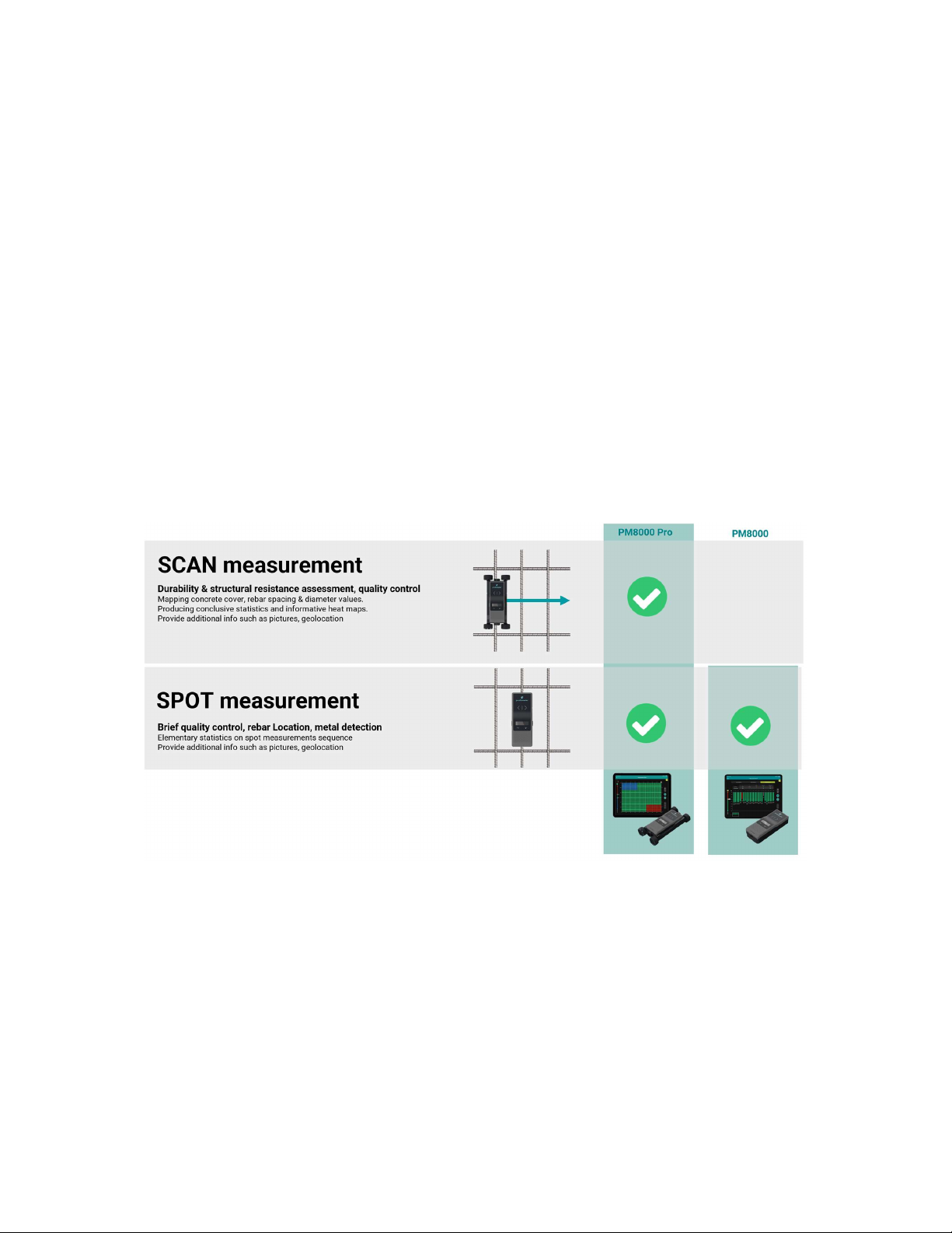
1.2 Product versions ...................................................................................................................6
1.3 Product applications .............................................................................................................8
2 Scope of Delivery .......................................................................................................... 9
3 Measurement Principle ............................................................................................... 10
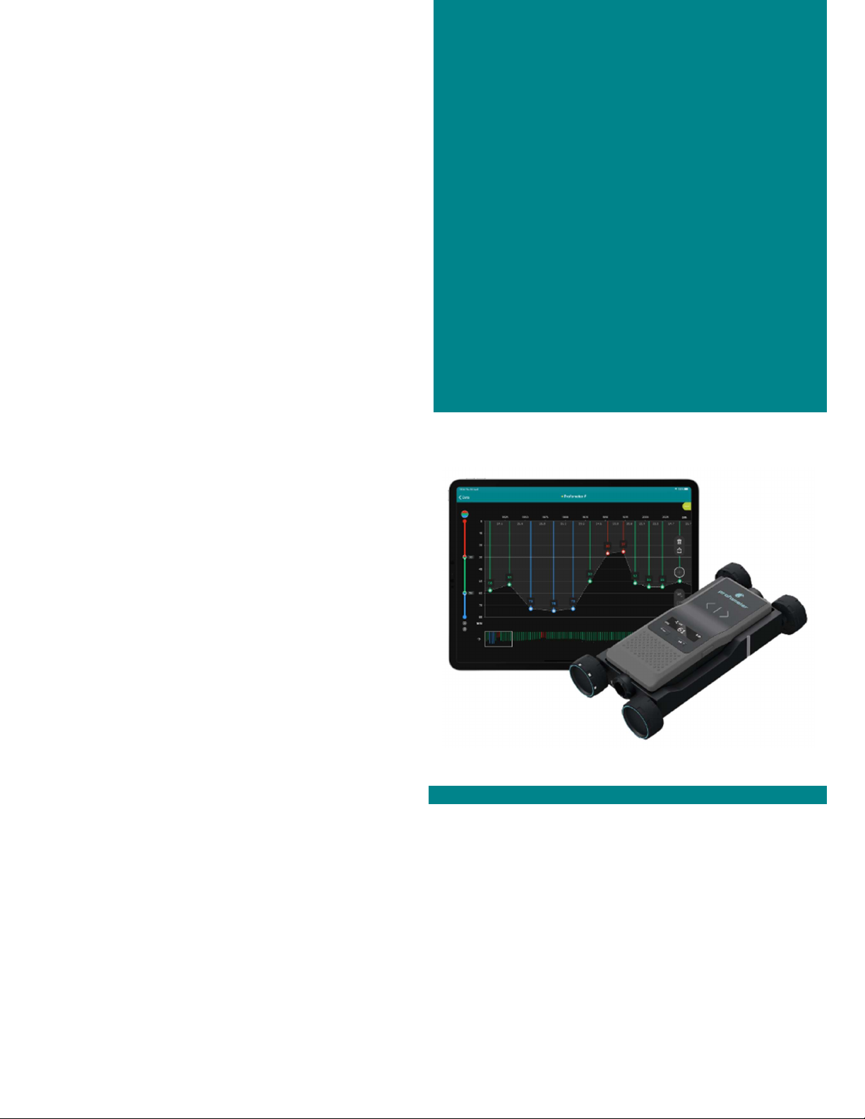
4 Device Overview .......................................................................................................... 11
4.1 Switching-on and getting started ....................................................................................... 11
4.2 Visual indicators ................................................................................................................. 12
4.3 Keys ................................................................................................................................... 12
4.3.1 Spot measurement ....................................................................................................... 12
4.3.2 Scan measurement ...................................................................................................... 13
4.4 Measurement Screen for spot measurement .................................................................... 13
4.5 Tracking Indicator .............................................................................................................. 14
4.6 General use ....................................................................................................................... 14
4.6.1 Main Menu Items ......................................................................................................... 15
4.6.2 Setting Reference Rebar Diameter .............................................................................. 15
4.6.3 Set Operation Mode ..................................................................................................... 16
4.6.4 Set Minimum Cover Alert limit ..................................................................................... 16
4.6.5 Neighboring rebar correction ....................................................................................... 17
4.6.6 Measuring Range ......................................................................................................... 17
4.6.7 Audio ............................................................................................................................ 18
4.6.8 Units ............................................................................................................................. 18
4.6.9 Memory ........................................................................................................................ 19
4.6.10 Device Info ................................................................................................................... 21
4.7 PM8000 Measuring Range ................................................................................................ 22
4.7.1 Measuring range without the cart ................................................................................ 22
4.7.2 Measuring with the cart ................................................................................................ 23
4.8 Factors Affecting the Measurement ................................................................................... 24
4.8.1 Errors due to Neighboring Rebars ............................................................................... 24
4.8.2 Resolution .................................................................................................................... 25
4.8.3 Effect of Setting Incorrect Rebar Diameter .................................................................. 25
4.8.4 Factors Affecting Diameter Determination ................................................................... 26
4.8.5 Orientation ................................................................................................................... 27
5 Operation and handling .............................................................................................. 29
5.1 Initial setup ......................................................................................................................... 29
5.2 Performing a Calibration .................................................................................................... 29
5.3 Measurement process ....................................................................................................... 30
5.3.1 Finding a Rebar, midpoint line or rebar orientation ..................................................... 30
5.3.2 Map out the rebar grid.................................................................................................. 35
5.4 Measurement files visualization & storage ........................................................................ 36
5.4.1 Spot scan measurements ............................................................................................ 36
5.4.2 line scan measurements .............................................................................................. 37
5.4.3 Area scan measurements ............................................................................................ 37
5.4.4 Statistics & Advanced statistics ................................................................................... 37
5.4.5 Heat Maps .................................................................................................................... 38
5.4.6 Data storage, reading, sharing & reporting .................................................................. 39
6 Application hints ......................................................................................................... 40
7 Technical Specification ............................................................................................... 41

17. April 2023 © Copyright 2023, PROCEQ SA 4
Legal Notice
This document contains important information on the safety, use and maintenance of Proceq
products. Read through this document carefully before the first use of the instrument. Observe
the safety and warning notes in this documentation and on the product. This is a prerequisite
for safe working and trouble-free operation.
Symbols used
This icon signals important information, specifications, proper working procedure and to
avoid data loss, damage or destruction of the instrument.
This note signifies a warning about dangers to life and limb if the apparatus is handled
improperly. Observe these notes and be particularly careful in these cases. Also inform
other users on all safety notes. Besides the notes in this instruction manual the generally
applicable safety instructions and regulations for prevention of accidents must be
observed.
Limitation of use
The instrument is only to be used for its designated purpose as described herein.
Replace faulty components only with original replacement parts from Proceq.
Accessories should only be installed or connected to the instrument if they are expressly
authorized by Proceq. If other accessories are installed or connected to the instrument
then Proceq will accept no liability and the product guarantee is forfeited.
Liability
Our “General Terms and Conditions of Sales and Delivery” apply in all cases. Warranty and
liability claims arising from personal injury and damage to property cannot be upheld if they
are due to one or more of the following causes:
Failure to use the instrument in accordance with its designated use as described in the
product documentation.
Incorrect performance check for operation and maintenance of the instrument and its
components.
Failure to adhere to the instructions dealing with the performance check, operation and
maintenance of the instrument and its components.
Unauthorised modifications to the instrument and its components.
Serious damage resulting from the effects of foreign bodies, accidents, vandalism and
force majeure. All information contained in this documentation is presented in good faith
and believed to be correct. Proceq AG makes no warranties and excludes all liability as
to the completeness and/or accuracy of the information.
Safety Instructions
The equipment is not allowed to be operated by children or anyone under the influence of
alcohol, drugs or pharmaceutical preparations. Anyone who is not familiar with the instrument
must be supervised when using the equipment.
Reserved Rights
The content of this document is intellectual property of Proceq SA and prohibited to be copied
neither in a photomechanical or electronic way, nor in excerpts, saved and/or be passed on to
other persons and institutions. This document can be changed at any time and without any
prenotification or announcement.
Unauthorized modifications and changes of the product are not permitted.

17. April 2023 © Copyright 2023, PROCEQ SA 5
Damages during carriage
On receipt of the goods, check for any visible damages on the packaging. If it is undamaged
you may sign the receipt of the goods. If you do suspect by visual inspection that damage has
occurred, make a note of the visible damage on the delivery receipt and request the courier to
countersign it. Moreover, the courier service must be held responsible for the damage in
writing.
If a hidden damage is discovered while unpacking, you have to inform and hold the courier
liable immediately in the following way: “When opening the parcel we had to notice that … etc.“
This superficial checking of the goods has to be done within the time limit set by the carrier,
which is normally 7 days. However, the period could vary depending on the courier. Hence, it
is recommended to check the exact time limit when receiving the goods.
If there are any damages also inform your authorized Proceq agent or Proceq SA immediately.
Shipment
Should the device be transported again, it must be packaged properly. Preferably use the
original packaging for later shipments. Additionally, use filling material in the package to protect
the device from any shock during carriage.
Safety notes and hints
All maintenance and repair work which is not explicitly permitted and described in the
present manual shall only be carried out by Proceq SA or your authorized service center,
failure to comply voids warranty.
Proceq SA refuses all warranty and liability claims for damages caused by usage of the
product in combination with non-original accessories, or accessories from 3rd party
suppliers.
Never immerse the device in water or other liquids: Danger of short circuit!
Never leave the product under direct sun exposure. Always store the product in its
carrying case.
For the operation of the product all local safety regulations apply.

17. April 2023 © Copyright 2023, PROCEQ SA 6
1 Introduction
PM8000 Pro and PM8000 are high quality instruments used to locate rebars, measure
concrete cover of rebars and estimate rebar diameters in concrete structures.
The product consists of
the PM8000 high-performance sensor,
the pm iOS app
and the Screening Eagle Workspace platform.
Figure 1: PM8000 System
The PM8000 sensor can be used in two different configurations:
Standalone
Connected
Via low power Bluetooth the PM8000 sensor wirelessly connects to the iPad, which runs
the pm app. Given mobile data connectivity (Wi-Fi or mobile network), the pm app
automatically and safely stores all measurements on the Screening Eagle Workspace.
1.1 Scope of this document
This document is the user manual for all products of the PM8000 Product family.
Therefore, some pictures or functional descriptions may differ from your model.
1.2 Product versions
In order to be able to use the functionality of the pm app, a software license is required.
The following licenses are available and offer different functionality:
Profometer License
Profometer Pro License

17. April 2023 © Copyright 2023, PROCEQ SA 7
Please refer to the table below for the supported features of the respective licenses:
Profometer App
Pro License
Profometer App
License
Measurement Modes Spot data import Spot data import
Line Scan
Area Scan
Cover offset*
Rebar Spacing Measurements
(1st layer)
Auto rebar spacing
Manual rebar spacing Manual rebar spacing
Neighboring Rebar Correction
(NRC)
1st layer NRC 1st layer NRC
2nd layer NRC
Statistics Standard Statistics
DBV advanced statistics (Deutscher
Beton- und Bautechnik-Verein)
Standard Statistics
Line Scan Concrete cover & rebar diameter view
Signal strength view
Area Scan Area scan concrete cover & rebar
diameter view
Heat map
AR (Augmented Reality) Heatmap
Logbook Measurements data, Instrument
Information, Pictures, Geolocation, text
notes, audio notes, configuration log
Measurements data, Instrument
Information, Pictures, Geolocation, text
notes, audio notes, configuration log
Data Sharing URL exchange URL exchange
Data Exporting CSV CSV
HTML HTML
JPG (Snapshot) JPG (Snapshot)
Data Synchronization Screening Eagle Workspace, automatic Screening Eagle Workspace, automatic
Screening Eagle Inspect Integration Screening Eagle Inspect Integration

17. April 2023 © Copyright 2023, PROCEQ SA 8
1.3 Product applications
In general, two measurement types can be differentiated:
Spot measurement (standalone)
For brief quality control, rebar location or metal detection a spot measurement is
performed.
Spot measurements are done in standalone configuration and provide measurement
values, such as concrete cover. For a sequence of spot measurements, the pm app can
be used to collect elementary statistics and to attach additional information such as
pictures, geolocation to the measurement series.
Scan measurement (connected, only for PM8000 Pro)
For durability & structural resistance assessment, quality control, mapping of concrete
cover, determination of rebar spacing & diameter values a scan measurement is
performed.
Scan measurements are producing numerical and visual measurement data, conclusive
statistics. The measurement data can be visualized in various form, e.g. in an informative
heat maps. Additional data such sensor information, pictures, geolocation ensure
professional documentation of the measurement.
Figure 2: Application overview

17. April 2023 © Copyright 2023, PROCEQ SA 9
2 Scope of Delivery
Please refer to the Quick start Guide provided in the standard delivery and available in
download section of the product webpage:
profometer-pm8000-QSG.pdf (screeningeagle.com)

17. April 2023 © Copyright 2023, PROCEQ SA 10
3 Measurement Principle
PM8000 uses electromagnetic pulse induction technology to detect rebars. Coils in the probe
are periodically charged by current pulses and thus generate a magnetic field. On the surface
of any electrically conductive material which is in the magnetic field eddy currents are induced.
They produce a magnetic field in the opposite direction. The resulting change in voltage can
be utilized for the measurement.
Figure 3: Measurement principle
PM8000 uses different coil arrangements to generate several magnetic fields. Advanced signal
processing allows
1. Localization of a rebar
2. Localization of the mid-point between rebars.
3. Determination of the cover
4. Estimation of the bar diameter
This method is unaffected by all non-conductive materials such as concrete1, wood, plastics,
bricks etc. However, any kind of conductive materials within the magnetic field (approx. 400
mm / 16” sphere) will have an influence on the measurement.
Remove all metallic objects such as rings, watches, and all electromagnetic wave
generators (smartphones, high voltage equipment etc.) from the area before you start
measuring!
1 Some concrete types and other structural materials may have metallic content.

17. April 2023 © Copyright 2023, PROCEQ SA 11
4 Device Overview
4.1 Switching-on and getting started
Please refer to the Quick Start Guide (included in standard delivery) for first steps with your
PM8000. The Quick Start Guide is also available in the download section of the product
webpage : profometer-pm8000-QSG.pdf (screeningeagle.com)
The main instructions for getting started are presented in Figure 4, Figure 5 & Figure 6
Be careful when you get the sensor in the cart. Make sure that your fingers are not
trapped in the assembling space.
Figure 4 : Inserting batteries
Figure 5 : Switching-on for standalone operation
Figure 6 : Switching-on for connected operation

17. April 2023 © Copyright 2023, PROCEQ SA 12
4.2 Visual indicators
The visual indicators show quickly and easily the proximity of a metallic object. The exact
location where the sensor measures is indicated by the measurement center mark.
The arrows right and left with LED indicate the rebar or metallic object proximity.
Figure 7: Visual indicators
4.3 Keys
4.3.1 Spot measurement
In stand-alone operation the four keys of the sensor allow the user to control the instrument
and navigate the sensor menu. Figure 8 shows the function assigned to the keys.
Figure 8: Keys functions in standalone operation
Measurement Center (MC)
Left Arrow Right
Arrow

17. April 2023 © Copyright 2023, PROCEQ SA 13
4.3.2 Scan measurement
When the sensor used connected with the pm App the key functions assignment is different.
Figure 9: Key functions in connected operation
For more information, please refer to the tutorial videos of pm app (Profometer app
downloadable from iOS App store).
4.4 Measurement Screen for Spot measurement
Figure 10: Overview Measurement Screen in stand-alone operation
(*) Depending on the unit setting

17. April 2023 © Copyright 2023, PROCEQ SA 14
4.5 Tracking Indicator
It is possible to activate the tracking indicator allowing to visualize the rebar or metallic object.
To activate the tracking indicator, the left side key must be short-pushed during the calibration
as explained in Figure 11. The deactivation of the tracking indicator follows the same button
press sequence.
Figure 11: Activation of Tracking indicator
Read section 5.3 to learn how to use the tracking indicator.
4.6 General use
In stand-alone operation, the PM8000 sensor can be operated and configured by the function
keys. The left function key allows to enter the sensor menu:
In the menu the function keys can be used to navigate through the menu items:

17. April 2023 © Copyright 2023, PROCEQ SA 15
4.6.1 Main Menu Items
Several menu items are available for changing the settings, configurations and access to the
device information.
Figure 12: Menu item overview
4.6.2 Setting Reference Rebar Diameter
With the correct rebar diameter setting, the precision of cover measurement and rebar
diameter estimation increases significantly.
In this menu you can set the real rebar diameter value, it’s known from construction data (BIM,
as-built drawings) or inspection hole.
If the rebar diameter is unknown, then keep the default diameter of 16 mm / #5
Figure 13: Menu - Setting rebar diameters

17. April 2023 © Copyright 2023, PROCEQ SA 16
4.6.3 Set Operation Mode
In standalone operation, it is important to select the right mode before spot measurement.
In this menu you can select on the three different modes:
Locate:
Rebar location, measurement reading, metal detection
Spot Scan Auto:
Any measurement is stored automatically (without pushing any button).
Spot Scan Manual:
Any measurement is stored manually by short pushing Left Side Key
For both spot scan modes: if the rebar diameter is measured then the value is also stored
along the displayed cover value stored automatically or manually.
Create a new series or switch mode for stopping a series.
Figure 14: Menu – Operation Mode
4.6.4 Set Minimum Cover Alert limit
Having a cover alert allows the user to identify the insufficient cover areas.
In this menu you can set the minimum cover alert limit. The measurement center LED is lit
when the cover is below this limit. If audio is on (see section 4.6.7), an audio signal is
generated.
Having a cover alert allows the user to identify the insufficient cover areas.
Figure 15: Menu - Minimum cover alert limit

17. April 2023 © Copyright 2023, PROCEQ SA 17
4.6.5 Neighboring rebar correction
Cover and rebar diameter measurements are influenced by neighboring rebars. This can be
compensated by using the Neighboring Rebar Correction (NRC).
In this menu, you can activate the neighboring rebar correction by setting the known rebar
spacing.
Please note, that this only works correctly, if the rebar spacing of first rebar layer(=mat)
is under 130mm / 5.2 inch.
If you do not know the rebar spacing, you can measure it manually by locating several
1st layer rebars, or get it from the construction data (BIM, as-built drawings) or inspection
hole.
Figure 16: Menu - Neighboring Rebar Correction
4.6.6 Measuring Range
The pulse induction principle used by PM8000 has defined operating ranges and accuracies.
The measuring range is dependent on the rebar size. The expected accuracy of the cover
measurement is indicated in section 4.8 .
In this menu you can select the right measuring range depending on the rebar or metallic object
depth:
Standard : <80mm / 3.15 inch (Default)
Deep : from 80mm to 180mm / 3.15 inch to 7.10 inch
Auto : Switches automatically from Standard to Deep
Rebar diameter estimation can be performed only in Standard measuring range because
of depth limitation, it cannot be performed in Deep measuring range!

17. April 2023 © Copyright 2023, PROCEQ SA 18
Figure 17: Menu - Measuring Range Setting
4.6.7 Audio
The device can give an audible tone to assist in location or to give useful alarms.
In this menu you can select/deselect the sound settings for the following alerts
(Default: all off) :
Rebar center detected
Minimum Cover alert
Key pressed
Figure 18 : Menu - Audio
4.6.8 Units
In this menu you can select your regional unit setting:
Metric
ASTM inch
ASTM mm
Japanese
The units settings affect all other displays and should be done prior to making other
selections.

17. April 2023 © Copyright 2023, PROCEQ SA 19
Figure 19 : Menu - Units
4.6.9 Memory
The PM8000 sensor has a memory capacity of 50 measurement files.
When the memory capacity is full, a warning icon is visible (as described in section 4.4).
The user has then 3 choices:
1. Do nothing. Any new spot measurement series will overwrite an existing one.
2. Manually delete all spot measurements series as explained in Figure 20.
Figure 20 : Menu – Memory
3. Connect to pm app installed in an iPad to import all the spot measurement series. This
automatically deletes all measurement series from the sensor memory. Given mobile
data connectivity (Wifi or mobile network), the pm app automatically and safely stores
all spot measurement series on the Screening Eagle Workspace by synchronizing with
the iPad.

17. April 2023 © Copyright 2023, PROCEQ SA 20
Figure 21 : pm app – sensor connected to iPad
Figure 22 : pm app – import spot data
For more information on how to import spot measurement data into pm app software, please
refer to the tutorial video named “Sensor Spot data” either in pm app or Youtube videos
(https://youtube.com/playlist?list=PLxVorw5ptOuIZfVeUt60cYYWnNiMcagYu)
This manual suits for next models
3
Table of contents
Popular Measuring Instrument manuals by other brands

HIK VISION
HIK VISION DS-8108LHFHI-K2 quick start guide

Extech Instruments
Extech Instruments RPM250W quick start

Electronics International Inc
Electronics International Inc M-1 Operating and installation instructions

Concept2
Concept2 PM1 Disassembly guide

Check-line
Check-line CDT-1000HD operating instructions

Tinker & Rasor
Tinker & Rasor CPV-2 Product instructions