GHM Greisinger GMH 5690 User manual

H84.0.14.6C-03
GHM GROUP - Greisinger
GHM Messtechnik GmbH | Hans-Sachs-Str. 26 | 93128 Regenstauf | GERMANY
Operating manual
Water-Proof oxygen meter for oxygen in gases
with integr. temperature & pressure measuring
As of version 1. 0
GMH 5690
Please carefully read these instructions before use!
WEEE-Reg.-Nr. DE 93889386
Please consider the safety instructions!
Please keep for future reference!

H84.0.14.6C-03 Operating manual GMH 5690 Page 2 of 18
_____________________________________________________ _____________________________________________________________________________
Contents
1SAFETY......................................................................................................................................................................3
1.1 GENERAL NOTE......................................................................................................................................................3
1.2 INTENDED USE.......................................................................................................................................................3
1.3 QUALIFIED STAFF ..................................................................................................................................................3
1.4 SAFETY SIGNS AND SYMBOLS................................................................................................................................3
1.5 REASONABLY FORESEEABLE MISUSE ....................................................................................................................4
1.6 SAFETY GUIDELINES..............................................................................................................................................4
2PRODUCT DESCRIPTION......................................................................................................................................4
2.1 SCOPE OF SUPPLY ..................................................................................................................................................4
2.2 OPERATION AND MAINTENANCE ADVICE..............................................................................................................5
3START OF OPERATION.........................................................................................................................................5
4OPERATION..............................................................................................................................................................5
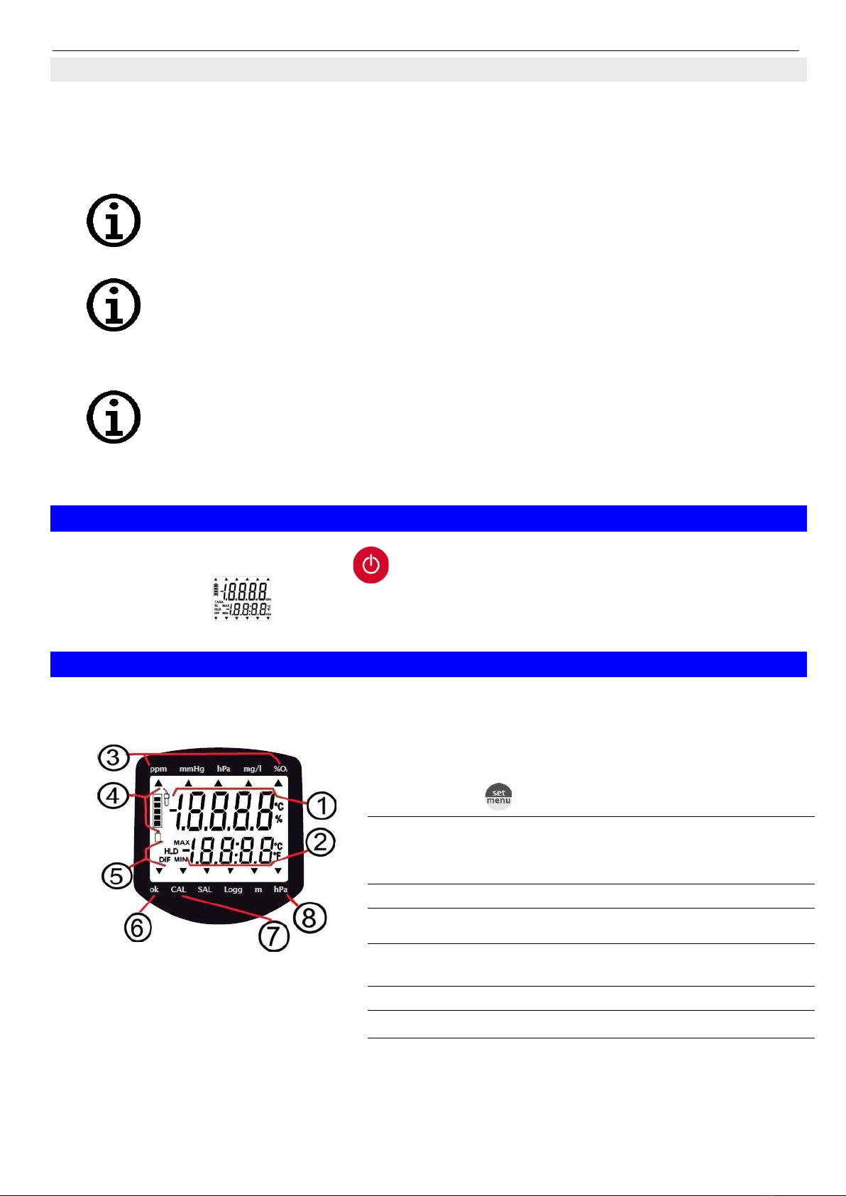
4.1 DISPLAY ELEMENTS...............................................................................................................................................5
4.2 PUSHBUTTONS.......................................................................................................................................................6
4.3 CONNECTIONS .......................................................................................................................................................6
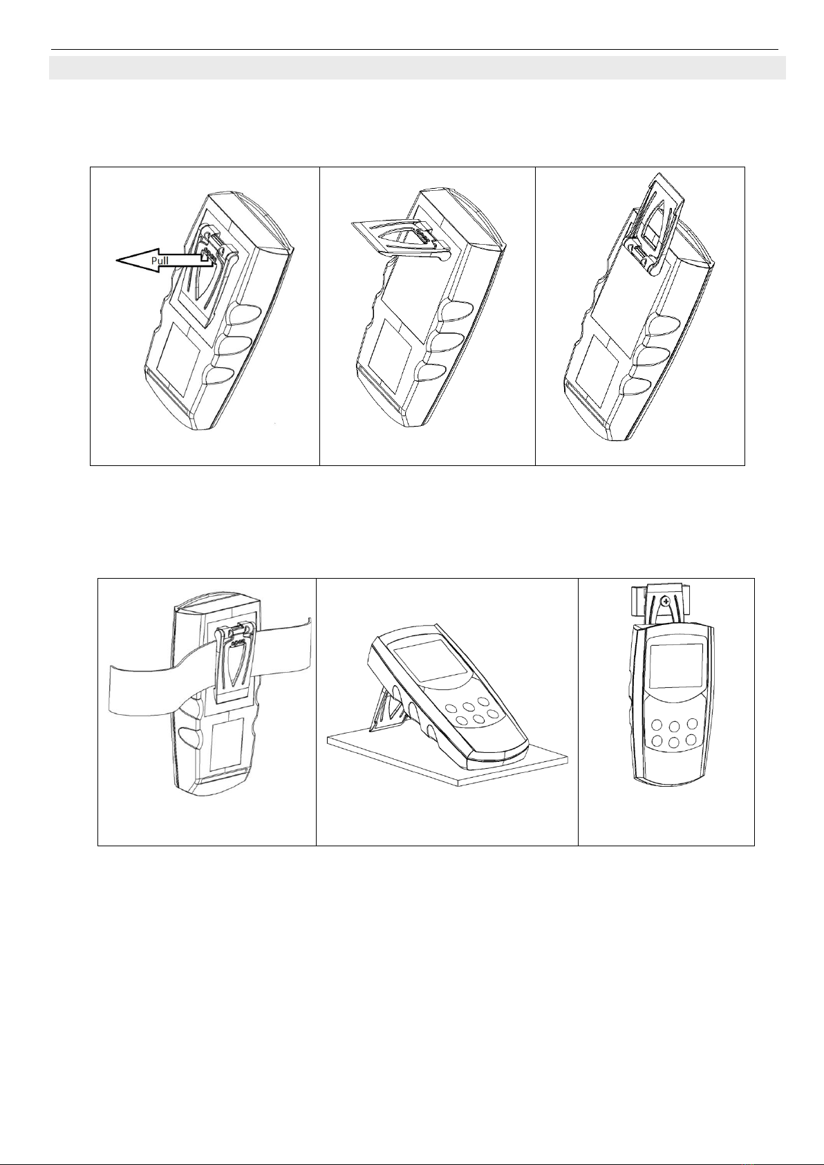
4.4 POP-UP CLIP...........................................................................................................................................................7
5CONFIGURATION...................................................................................................................................................8
6THE OXYGEN SENSOR..........................................................................................................................................9
6.1 GENERAL NOTES ABOUT THE OXYGEN SENSOR.....................................................................................................9
6.1.1 Life time .........................................................................................................................................................9
6.1.2 Mounting /operation position.......................................................................................................................10
6.1.3 Measuring precision ....................................................................................................................................10
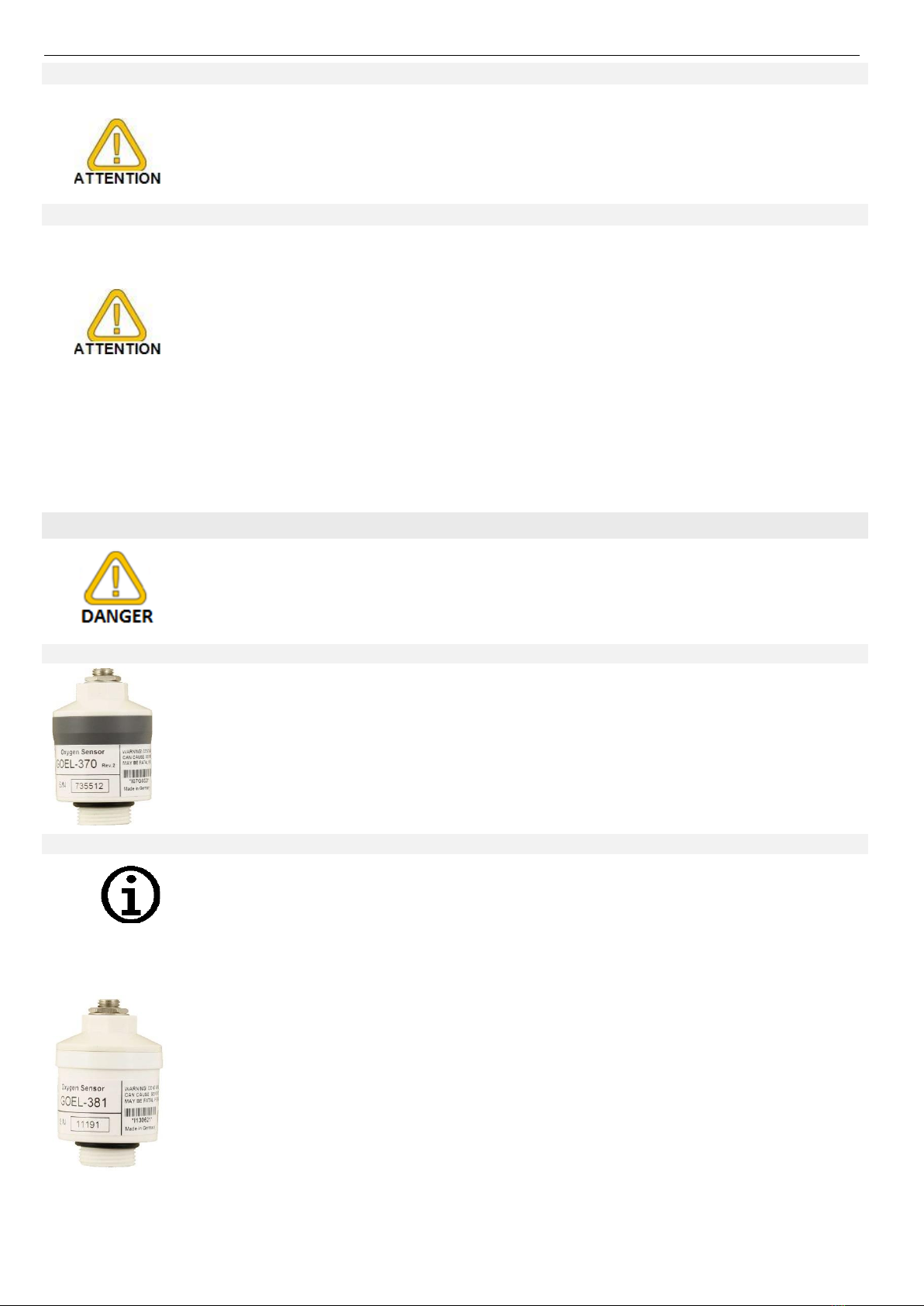
6.2 SENSOR ELEMENTS..............................................................................................................................................10
6.2.1 GOEL 370 acidic electrolyte........................................................................................................................10
6.2.2 GOEL 381 basic electrolyte.........................................................................................................................10
7OXYGEN MEASURING IN GASES- PLEASE NOTE.......................................................................................11
7.1 APPLICATION OF THE DIFFERENT SENSOR TYPES ................................................................................................11
7.1.1 GGO housing (closed sensor)......................................................................................................................11
7.1.2 GOO housing (open sensor) ........................................................................................................................11
8EXCHANGING THE SENSOR ELEMENT.........................................................................................................11
9CALIBRATION OF THE OXYGEN SENSOR....................................................................................................12
9.1 ONE POINT CALIBRATION “(AL. 1-PT“.................................................................................................................12
9.2 2/3- POINT CALIBRATION ”(AL 2-PT“,”(AL 3-PT“..........................................................................................12
9.3 EVALUATION OF SENSOR STATE “ELE[“..............................................................................................................13
9.4 CALIBRATION/ADJUSTMENT INTERVAL “[INT“...................................................................................................13
10 ADJUSTMENT OF TEMPERATURE INPUT.................................................................................................13
11 ALARM “AL.“........................................................................................................................................................13
12 UNIVERSAL OUTPUT .......................................................................................................................................14
12.1 INTERFACE.......................................................................................................................................................14
12.1.1 Supported interface-functions:.....................................................................................................................14
13 INSPECTION OF THE ACCURACY/ ADJUSTMENTS AERVICES ..........................................................15
14 BATTERY CHANGE...........................................................................................................................................15
15 ERROR AND SYSTEM MESSAGES................................................................................................................16
16 RESHIPMENT AND DISPOSAL.......................................................................................................................17
16.1 RESHIPMENT ....................................................................................................................................................17
16.2 DISPOSAL.........................................................................................................................................................17
17 SPECIFICATION.................................................................................................................................................17

H84.0.14.6C-03 Operating manual GMH 5690 Page 3 of 18
_____________________________________________________ _____________________________________________________________________________
1 Safety
1.1 General note
Read this document attentively and make yourself familiar to the operation of the device before you use it.
Keep this document in a ready-to-hand way in order to be able to look up in the case of doubt.
Mounting, start-up, operating, maintenance and removing from operation must be done by qualified,
specially trained staff that have carefully read and understood this manual before starting any work.
The manufacturer will assume no liability or warranty in case of usage for other purpose than the intended
one, ignoring this manual, operating by unqualified staff as well as unauthorized modifications to the device.
The manufacturer is not liable for any costs or damages incurred at the user or third parties because of the
usage or application of this device, in particular in case of improper use of the device, misuse or
malfunction of the connection or of the device.
The manufacturer is not liable for misprints.
1.2 Intended use
The instrument is measuring oxygen in air and gas mixtures either as partial pressure or as concentration in
% Vol. O2.
For the measuring an external sensor of the type GOO-... or GGO... is necessary.
The measuring take place at the extern opening Sensor.
Due to the properties of the sensor, it has to be calibrated regularly (e.g. at fresh air = 20.95 % Vol. O2) to get
precise values. If the sensor is used up, this will be detected during the calibration, the sensor has to be
regenerated or replaced before continuing with measuring.
The sensor has to be connected to the 7-pole bayonet socket.
The safety requirements (see below) have to be observed.
The device must be used only according to its intended purpose and under suitable conditions.
1.3 Qualified staff
All instructions have to be well understood and complied with. To be sure that there is no risk arising due to
misinterpretation of measured values, the operator must have further knowledge in case of doubt - the user
is liable for any harm/damage resulting from misinterpretation due to insufficient knowledge.
1.4 Safety signs and symbols
Warning notices are marked in this manual as shown below:
Caution! This symbol warns of imminent danger, death, serious injuries and significant
damage to property at non-observance.
Attention! This symbol warns of possible dangers or dangerous situations, which can
provoke damage to the device or environment at non-observance.
Note! This symbol points out processes, which can indirectly influence operation or
provoke unforeseen reactions at non-observance.
As of version 1. 0
GMH 5690

H84.0.14.6C-03 Operating manual GMH 5690 Page 4 of 18
_____________________________________________________ _____________________________________________________________________________
1.5 Reasonably foreseeable misuse
This device must not be used at potentially explosive areas!
Do not use these products as safety or emergency stop devices or in any other
application where failure of the product could result in personal injury or material
damage.
Failure to comply with these instructions could result in death or serious injury and
material damage.
This device must not be used at a patient for diagnostic or other medical purpose.
1.6 Safety guidelines
This device has been designed and tested in accordance with the safety regulations for electronic devices.
However, its trouble-free operation and reliability cannot be guaranteed unless the standard safety measures
and special safety advises given in this manual will be adhered to when using the device.
Trouble-free operation and reliability of the device can only be guaranteed if the device is
not subjected to any other climatic conditions than those stated under 17 Specification.
If there is a risk whatsoever involved in running it, the device has to be switched off
immediately and to be marked accordingly to avoid re-starting.
Operator safety may be a risk if:
- there is visible damage to the device
- the device is not working as specified
- the device has been stored under unsuitable conditions for a longer time.
In case of doubt, please return device to manufacturer for repair or maintenance.
Internal connections of other devices (e.g. from ground with protective earth) may lead to
prohibited voltage levels that could disturb the function, damage or even destruct the
device or any connected equipment.
2 Product description
2.1 Scope of supply
The scope of supply includes:
Handheld instrument GMH 5695 with 2 AAA-Batteries
(oxygen sensor usually is ordered separately. For choice please refer to chapter 6 The oxygen
sensor)
Operating manual
Short form manual
Calibration protocol
Silicone protective cover

H84.0.14.6C-03 Operating manual GMH 5690 Page 5 of 18
_____________________________________________________ _____________________________________________________________________________
2.2 Operation and maintenance advice
Battery operation:
If „BAT“ is shown in the lower display the battery has been used up and needs to be replaced. However, the
device will operate correctly for a certain time
If „BAT“ is shown in the upper display the voltage is too low to operate the device; the battery has been
completely used up. Battery change see chapter 14 Battery change.
The battery has to be taken out, when storing device above 50°C. We recommend taking
out battery if device is not used for a longer period.
After recommissioning, the real-time clock has to be set again.
Use device and sensor carefully and according to its technical data (do not throw it,
strike it, etc.). Protect the device from dirt.
USB or mains operation:
When connecting a mains cable or USB interface cable, please take care to connect only
allowed components.
The output voltage of a connected power supply unit has to be between 4.5 and 5.5 V
DC. Do not apply overvoltage!
We recommend operation with interface cable USB 5100. Then device is supplied by the
USB interface of the connected PC or USB power supply adapter.
3 Start of operation
Connect sensor, switch instrument on with ….
After the segment test the instrument shows “[ORR“shortly, if it was user adjusted.
The device starts measurement afterwards.
4 Operation
4.1 Display elements
1
Main display:
Oxygen concentration in % (% Vol. O2) or
Oxygen partial pressure (hPa or. mmHg)
Choice via - key
2
Secondary display:
sensor temperature or absolute pressure, (alternating,
please refer to chapter 5 Configuration ”LCD.2“
3
Main display units
4
State of battery
5
Shows, if minimum/maximum/
memorized measuring value is in display
6
Arrow ”ok“: Measured value is stable
7
Arrow “CAL“: Calibration
8
Arrow “hPa“: Pressure unit of internal sensor

H84.0.14.6C-03 Operating manual GMH 5690 Page 6 of 18
_____________________________________________________ _____________________________________________________________________________
4.2 Pushbuttons
On / off key, backlight
“press shortly“:
Activate backlight or switch on instrument
”press longer“:
Switch off instrument
Set/Menü
”press for 2 sec“ (menu):
Invoke configuration menu
”press shortly“:
Change oxygen display unit
+
min / max
”press shortly“:
Min. or max. value is displayed
”press for 2 sec“:
The corresponding value is deleted
Configuration
See chapter 5 Configuration:
Confirm settings, return to measuring
Store/Enter
”Measuring“:
with Auto-Hold off:
Hold and save current measuring value, (‘HLD’ is displayed)
with Auto-Hold on:
Start new measuring, It is finished , when “HLD’ shows in
display please refer to chapter 5 Configuration.
Configuration
See chapter 5 Configuration:
Confirm settings, return to measuring
[AL:
”press shortly“:
Shown the sensor state of the last calibration
”press for 2 sec“:
Start of the oxygen calibration
4.3 Connections
Universal output
Interface, supply, analog output see chapter 12
Universal output
7-pole bayonet socket
Connection for sensor and temperature probe

H84.0.14.6C-03 Operating manual GMH 5690 Page 7 of 18
_____________________________________________________ _____________________________________________________________________________
4.4 Pop-up clip
Handling
•Pull at label “open” in order to swing open the pop-up clip.
•Pull at label “open” again to swing open the pop-up clip further.
Pop-up clip closed
Pop-up clip at position 90°
Pop-up clip at position 180°
Function:
• The device with a closed pop-up clip can be plainly laid onto a table or attached to a belt, etc.
• The device with pop-up clip at position 90° can be set up on a table, etc.
• The device with pop-up clip at position 180° can be suspended from a screw or the magnetic holder
GMH 1300.
Device attached to a belt
Device set up on a table
Device suspended from
magnetic holder
GMH 1300

H84.0.14.6C-03 Operating manual GMH 5690 Page 8 of 18
_____________________________________________________ _____________________________________________________________________________
5 Configuration
To change device’s settings, press for 2 seconds. This will activate the configuration menu (main display
“SET“). Pressing changes between the menus points, pressing jumps to the referring parameters,
which can be selected with ).
The parameter value can be changed with or. . Pressing again jumps back to the main
configuration menu and saves the settings. Pressing finishes the configuration.
Pressing and at the same time for more than 2 seconds will reset the device to
factory defaults.
If no key is pressed for more than 2 minutes the configuration will be aborted. All
changes will be discarded!
Menu
Parameter
Value
Description
or
see
SET
(ONF
Set Configuration: General configuration
9
[H 2
P 02 hPa
Oxygen partial pressure display in hPa
*
P 02 mmHg
Oxygen partial pressure display in mmHg
RES
K,
Best O2resolution
LO
Low O2resolution, calm value display (standard)
LCD.2
T
Secondary display always temperature
P
Secondary display always absolute pressure
P T
Secondary display alternates between temperature and abs.
pressure
U N,T
T
°C
All temperatures in degree Celsius (ex works setting)
°F
All temperatures in degree Fahrenheit
[AL.P
1-PT
Simple one point calibration at air
2-PT /3-PT
2 or 3- calibration at air, or in oxygen or in nitrogen / zero gas
[. INT
1 …365
Calibration reminder period (in days)
OFF
No calibration reminder
A VTO
HLD
ON
Auto stable value determining freezing
OFF
Standard hold function on key press
P.OFF
1 …120
Power-off delay in minutes. Device will be automatically switched
off as soon as this time has elapsed if no key is pressed/no
interface communication takes place. (ex works setting 20min)
OFF
Automatic power-off function deactivated (continuous operation)
L,TE
OFF
Backlight deactivated
5...120
Turn off backlight after 5… 120 s (factory settings: 10 s)
ON
Backlight always on
0V T
OFF
Interface off -> minimal power consumption
SER
Serial interface activated (ex works setting)
DA[
Analog output activated
ADR
0 1,1 1,2 1,…9 1
Base address for serial interface communication (ex works
setting 01)

H84.0.14.6C-03 Operating manual GMH 5690 Page 9 of 18
_____________________________________________________ _____________________________________________________________________________
SET
(ORR
Set Corr: Input adjustment
**
9.4
0FFS
°C bzw. °F
-5.0 °C... 5.0 °C
or
-9.0 °F ... 9.0 °F
The zero point of the temperature measuring is shifted for the
entered value. This can be used to compensate sensor and
instrument deviations
**
OFF
No zero adjustment for temperature measurement (=0.0°)
S[AL
°C bzw. °F
-5.00 ... 5.00 %
The slope of the temperature measurement is corrected by this
value.
This can be used to compensate sensor and instrument
deviations
**
OFF
No slope adjustment for temperature measurement (=0.00)
0FFS
hPa
-20 ... 20 hPa
The zero point of the pressure measuring is shifted for the
entered value.
This can be used to compensate sensor deviations
**
OFF
No zero adjustment for pressure measurement (=0 hPa)
SET
AL
Set Alarm: Configuration of the alarm settings
11
AL. 1
ON /NO.SO
Monitoring oxygen: Alarm on with buzzer / Alarm on without
buzzer
OFF
No alarm monitoring for oxygen
AL.,N
[ONC
Monitoring oxygen: Concentration in % Vol O2
P. 02
Monitoring oxygen: Partial pressure in hPa or mmHg
A 1.LO
e.g. 0.0...100.0
%
Min alarm limit oxygen (not if AL. 1. oFF)
A 1.H,
e.g 0.0...100.0
%
Max alarm limit oxygen (not if AL. 1. oFF)
AL. 2
ON /NO.SO
Temperature monitoring : Alarm on with buzzer / Alarm on
without buzzer
OFF
No alarm monitoring for temperature
A2.LO
-5.0 ... +50.0 °C
Min alarm limit temperature (not if AL. 2. oFF)
A2.H,
-5.0 ... +50.0 °C
Max alarm limit temperature (not if AL. 2. oFF)
6 The oxygen sensor
6.1 General notes about the oxygen sensor
6.1.1 Life time
At the end of the life time, the signal of the sensor is dropping rapidly. The sensor evaluation in % therefore
can only be taken as a relative measure. An evaluation of 70% does not mean that 70% of life time is left, but
that the electrode signal has 70% of an optimal state reference.
The nominal life time may be reduced due to the application. Negative effects are:
Extreme storage and operation temperature.
Humidity of measured gas: If permanently used with dry gases (technical gases, bottled gas) the lifetime
decreases considerably.
The sensor state evaluation will be stored after a successful calibration of the oxygen
sensor.

H84.0.14.6C-03 Operating manual GMH 5690 Page 10 of 18
_____________________________________________________ _____________________________________________________________________________
6.1.2 Mounting /operation position
The optimum position for the sensor membrane is to point downwards.
If sensor is screwd in pressure.tight into an application wichs pressure differs from the
ambient pressure, the maximum differential pressure at the sensor membrane is 250 bar.
6.1.3 Measuring precision
The precision can be influenced due to:
Liquids at the sensor inlet. Rinse the inlet and dry with lint-free cloth.
Avoid liquids of any kind at the contacts.
Gas and sensor temperature have to be at same level. Best precision, when calibrated at measuring
temperature.
Pressure fluctuations: The sensor is originally a partial pressure sensor, i.e. changes in the absolute
pressure are influencing the measuring result directly proportional. A pressure change of 1% will cause a
additional measuring error of 1%!
For optimum precision calibrate at the same conditions at which you want to measure.
6.2 Sensor elements
Unsuitable for underwater-diving-application e.g. Rebreather.
6.2.1 GOEL 370 acidic electrolyte
Integrated in GGO 570, GGA 570, GOO 570.
Recommended application areas 0...35 Vol. % O2(above, the measuring accuracy
is reduced).
Also suitable for gases with high CO2-proportion or for CO2-gas. The effect of the
acidic electrolyte is that the sensor is resistant against the CO2-gas and still hold the
stability.
6.2.2 GOEL 381 basic electrolyte
Short-time exposition of up to 10% CO2is not problematic (for example 15 minutes.
up to 10 times per day) for the GOEL 380 (e.g. exhaust measuring). If there is
measured more often with elevated CO2-concentration or at CO2-concentrations
above 10%, the exposition time has to be kept as short as possible and sufficient
measuring breaks should be made.
If the sensor is not exposed to free air during measuring pauses, the connected
tubes etc. have to be flushed with clean air or nitrogen.
Integrated in GGO 581, GGA 581, GOO 581.
Recommended application areas 0...100 Vol. % O2.
Preferred of measurements with extremely small oxygen content (e.g. < 0.3 Vol. %
O2), e.g. protective atmosphere, or more than 35 % Vol O2.
For gases without larger CO2 concentration

H84.0.14.6C-03 Operating manual GMH 5690 Page 11 of 18
_____________________________________________________ _____________________________________________________________________________
7 Oxygen measuring in gases- please note
The instrument is designed for measuring the oxygen partial pressure or the oxygen concentration (% Vol.
O2) calculated from partial pressure and ambient pressure) in gases. Please keep in mind.
The sensor consists of a sensing element (GOEL 3xx) enclosed in a sensor housing (GGO/ GGA/ GOO).
When purchasing a sensor GGO/GGA/GOO 5xx, a sensor element is already integrated,
e.g. a GGO 570: contains housing GGO and a sensor element GOEL 370
7.1 Application of the different sensor types
7.1.1 GGO housing (closed sensor)
For measurements at atmosphere and in systems without over or under pressure, the GGO... is sufficient.
Additionally the GGO can be screwed tightly into systems with small
over or under pressure.
Attention! Mind the maximum pressure and the maximum pressure
difference at the membrane.
If instrument and sensor pressure are different, please connect the
pressure port of instrument to measuring pressure, otherwise it will
be compensated wrong!
7.1.2 GOO housing (open sensor)
The sensor is equipped with drillings at the end and because of its
special construction the measuring gas streams optimally around the
sensor. No pressure can appear while gas blows to the sensor, which
otherwise would result in erroneous measures. The temperature
compensation speed of the sensor also is optimised by this design.
Especially the measuring of gases from compressed gas bottles,
where the expansion of the gas leaving the bottle lowers the temperature, is optimised with regard to the
temperature compensation and pressure errors. The gas flow should be chosen in a suitable range, where
no overpressure can happen, esp. if the sensor is connected directly to the source e.g. by means of a tube.
8 Exchanging the sensor element
The sensor housings are consisting of two halves (1) and (4) and can be opened by screwing up:
GGO/GGA housing
GOO housing
GOG / ResOx 5695 housing
Changeable part is the sensor element (3). Important when reassembling:
- First screw in sensor (3) in part (1). Do not forget O-Ring (2)
Unscrew the sensor carefully e.g. by means of suitable nippers.
- The audio plug of part (4) has to be connected to the socket in the sensor. If this makes problems, the cable gland
(5) can be opened so that the cable can be shifted further into part (4), until the plug can be connected.
- After that screw together (1) and (4) tightly, if necessary retighten the cable gland (5).

H84.0.14.6C-03 Operating manual GMH 5690 Page 12 of 18
_____________________________________________________ _____________________________________________________________________________
9 Calibration of the oxygen sensor
In order to compensate for ageing of the sensor, the sensor has to be calibrated at
regular intervals.
The device is equipped with an easy-to-use calibration function.
We recommend to calibrate the sensor at least all 7 days, or to get maximum precision,
before each measuring series.
9.1 One point calibration “(AL. 1-PT“
The calibration adjusts the sensor to the oxygen content of the atmosphere (20.95 % Vol. O2) Therefore
simply expose the sensor to the ambient air (sufficient ventilation in closed rooms has to be ensured).
Start calibration: press for 2 seconds.
The display will show A,R , and as soon the values for oxygen and temperature are stable, the
calibration will be finished.
Then the sensor state resulting of the successful calibration will be shown for a short time evaluation in 10%
steps ”xx% ELE[“.
9.2 2 / 3- Point calibration ”(AL 2-PT“, ”(AL 3-PT“
The sensor will be automatically calibrated to the oxygen content of the atmosphere (20.95 % Vol. O2), and
one or two additional concentrations. As reference, gases usually Nitrogen (0 % Vol. O2) or pure oxygen are
used (100 % Vol. O2).
1. Start calibration: press: - key for 2 seconds.
2. First calibration reference: (Pt.1)
As first reference at a 3-point calibration, the zero reference has to be applied 0 % VOL O2.
at a 2-point calibration either 100 % Vol. O2or 0 % Vol. O2.
The display will show , and the referring reference which should be applied.
- 0.2 for pure oxygen.
- NULL for 0% oxygen (e. g. pure nitrogen).
As long as the display blinks, the instrument recognises no valid reference.
As soon the values for oxygen and temperature are stable, the calibration of the first point will be finished.
The instrument tells you to apply the next reference (possible references are blinking in the display).
3. Second calibration reference: (Pt.2)
The display will show , and the referring reference which should be applied.
- A,R for ambient air.
- 0.2 for pure oxygen.
- NULL for 0 % oxygen. (e. g. pure nitrogen).
As long as the display blinks, no valid reference is recognised by the instrument.
As soon the values for oxygen and temperature are stable, the calibration of the second point will be
finished. At 2-point calibration the calibration will be finished and the sensor state resulting of the successful
calibration will be shown for a short time evaluation in 10% steps ”xx% ELE[“.
At 3-point calibration, the instrument tells you to apply the next reference (possible reference is blinking).
1. Third calibration reference: (Pt.3)
The display will show , and the referring reference which should be applied:
As soon the values for oxygen and temperature are stable, the calibration of the second point will be
finished. At 2-point calibration the calibration will be finished and the sensor state resulting of the successful
calibration will be shown for a short time evaluation in 10% steps ”xx% ELE[“.
In case of error messages being displayed during the calibration process, please refer to
our notes at the end of this manual! If a calibration cannot be carried out after an
extended period of time, at least one of the measuring values is unstable (oxygen partial
pressure, temperature).
Please check your measuring arrangements!

H84.0.14.6C-03 Operating manual GMH 5690 Page 13 of 18
_____________________________________________________ _____________________________________________________________________________
9.3 Evaluation of sensor state “ELE[“
Watch sensor state: press shortly once, display shows ”xx% ELE[“for a short time.
It will show the sensor state resulting of the last successful calibration carried out.
The evaluation is displayed in 10 % steps: 100% means optimal sensor condition. Lower values are
indicating that the sensor life time will be reached soon.
But also an erroneous pressure may be the cause of low valuation values.
9.4 Calibration/ adjustment interval “[INT“
You can input the interval after which the device reminds you to recalibrate.
The interval times should be chosen according to the application and the stability of the sensor „[AL“flashes
on the display as soon as the interval has expired.
10 Adjustment of temperature input
The temperature input can be adjusted with offset and scale. A reasonable adjustment presumes reliable
references (e.g. ice water, controlled precision water bath, etc.). If the inputs are adjusted (i.e. offset and
scale are different from default settings) the device will shortly display ”(ORR“ after turned on.
Default setting for offset and scale are ‘off’ = 0.0, i.e. inputs are not changed.
Zero point correction: Displayed value = measured value 0FFS.
Zero point and slope correction: Displayed value = (measured value - 0FFS) • (1 + S[AL / 100).
Displayed value °F = (meas. value °F - 32°F - 0FFS) (1 + S[AL /100).
11 Alarm “AL.“
There are 3 possible settings:
off “AL.OFF“, on with buzzer “AL. ON“, on without buzzer “AL. NO.SO“.
Alarm is given in the following cases if alarm active (ON or NO.SO):
-Lower alarm boundary (A 1.LO) under-run
-Upper alarm boundary (A 1.H,) over-rum.
-Sensor error.
-Low battery (BAT)
-Err.7: system error (always with buzzer).
In case of an alarm and when polling the interface the ‚PRIO-flag is set in the returned interface message.

H84.0.14.6C-03 Operating manual GMH 5690 Page 14 of 18
_____________________________________________________ _____________________________________________________________________________
12 Universal output
The output can be used as serial interface (for USB5100 interface converter). If the output is not needed, it is
strongly recommended to deactivate it (Out oFF), to lower power consumption. This increases battery life
time.
If the device is used together with interface adapter USB 5100 the device is supplied from the interface
device pin assignment
1: external supply +5V, 50mA
2: GND
3: TxD/RxD (3.3V Logic)
4: +UDAC, analog output
Only suitable adaptor cables are permitted (accessories)!
12.1 Interface
The device can be directly connected to a PC at the USB interface, with an electrically isolated interface
converter USB 5100 (accessory). The transfer takes place via a binary coded format and is protected for
transmission errors, by elaborated security mechanisms.
The following standard software packages are available:
EBS20M / -60M: 20-/60-channel software for measuring value display
GMHKonfig: Configuration Software (for free on internet)
In case you want to develop your own software, we offer a GMH3000- development package including:
a universally applicable Windows functions library ('GMH3000.DLL') with documentation, can be used by
all ‘established’ programming languages, suitable for, Windows XP™,
Windows Vista™, Windows 7™, Windows 8 / 8.1™, Windows 10™
Programming examples Visual Studio 2010 (C#, C++ und VB), Testpoint™, LabVIEW™ etc.
The device has 4 channels:
- Oxygen concentration in % Vol. O2.
- Oxygen partial pressure in hPa or mmHg.
- Temperature value at the time of recording in °C or °F.
- Absolute pressure in hPa abs or mmHg abs.
12.1.1 Supported interface-functions:
1
2
3
4
Code
Name/Function
1
2
3
4
Code
Name/Function
x
x
x
x
0
read nominal value
x
x
x
x
199
read measuring type in display
x
x
x
x
3
read system status
x
x
x
x
200
read min. display range
x
12
read ID-no.
x
x
x
x
201
read max. display range
x
x
x
22
read min alarm limit
x
x
x
x
202
read unit of display
x
x
x
23
read max alarm limit
x
x
x
x
204
read decimal point of display
x
x
x
x
176
read min. measuring range
x
208
read channel count
x
x
x
x
177
read max. measuring range
x
222
read turn-off-delay
x
x
x
x
178
read measuring range unit
x
223
Set turn-off-delay
x
x
x
x
179
read measuring range decimal point
x
240
Reset
x
x
x
x
180
read measuring type
x
254
read program identification
The measuring and range values read via interface are always in the selected display unit!

H84.0.14.6C-03 Operating manual GMH 5690 Page 15 of 18
_____________________________________________________ _____________________________________________________________________________
13 Inspection of the accuracy/ adjustments aervices
The instrument can be sent to the manufacturer for adjustment and function test.
Only the manufacturer can check all systems on correct them if necessary.
Calibration certificates –DKD-certificates –other certificates:
There it is actually not possible to certificate the device for solved oxygen measurement, only for temperature
and pressure measurement.
14 Battery change
Before changing batteries, please read the following instruction and follow it
step by step.
Not following the instruction may cause harm to the instrument or the
protection against ingress of water and dust may be lost!
Avoid unnecessary opening of the instrument!
1. Open the 3 Phillips screws at the backside of the instrument.
2. Lay down the still closed instrument, so that the display side points
upwards.
The lower half of the housing incl. the electronics should be kept lying
down during battery change.
This avoids loss of the 3 sealing rings placed in the screw holes.
3. Lift off upper half of housing. Keep an eye on the six function keys, to
be sure not to damage them.
4. Change carefully the two batteries (Type: AAA).
5. Check: Are the 3 sealing rings placed in the housing?
Is the circumference seal of the upper half sound and clean?
Close the housing, taking care that it is positioned correctly, otherwise the
sealing may be damaged. Afterwards press the two halves together, lay the
instrument with display pointing downwards and screw it together again
Take care to screw only until you feel increasing resistance, higher screwing force does
not result in higher water protection!

H84.0.14.6C-03 Operating manual GMH 5690 Page 16 of 18
_____________________________________________________ _____________________________________________________________________________
15 Error and System Messages
Display
Meaning
Remedy
low battery voltage, device will continue to work
for a short time
replace battery
If mains operation: wrong voltage
replace power supply, if fault continues to
exist: device damaged
low battery voltage
replace battery
If mains operation: wrong voltage
Check/replace power supply, if fault
continues to exist: device damaged
No display
or
weird display
Device does not
react on keys
low battery voltage
replace battery
If mains operation: wrong voltage
check/replace power supply, if fault
continues to exist: device damaged
system error
disconnect battery or power supply, wait
some time, re-connect
device defective
return to manufacturer for repair
SENS
ERRO
sensor error: no sensor cable connected
connect suitable sensor
Sensor, cable or instrument defect
return to manufacturer for repair
ERR.1
Value exceeding measuring range
Check: Is the value exceeding the specified
measuring range? ->value too high!
Wrong sensor connected
Check sensor
Sensor, cable or instrument defect
return to manufacturer for repair
ERR.2
Value below display range
Check: Is the value below the specified
measuring range? ->value too low!
Wrong sensor connected
Check sensor
Sensor, cable or instrument defect
return to manufacturer for repair
ERR.7
system error
return to manufacturer for repair
If “BAT“is flashing, the battery will be exhausted soon. Further measurements are possible for short time.
If “BAT“is displayed continuously the battery is ultimately exhausted and has to be replaced. Further
measurements aren’t possible any more.
Messages During Calibration/Adjustment
>CAL<
CAL flashing in
display
either preset calibration interval has expired or
last calibration is not valid
device has to be calibrated!
[AL ERR.1
wrong reference point at air
check sensor and reference gas
[AL ERR.2
slope too low
reference gas wrong
check sensor and reference gas
sensor element is defect
replace sensor element
[AL ERR.3
slope too high
reference gas wrong
check sensor and reference gas
sensor element is defect
replace sensor element
[AL ERR.4
incorrect calibration temperature
calibration can only be done at 0…50 °C
[AL ERR.5
Zero value to low/negative
sensor element is defect
replace sensor element
[AL ERR.6
zero value to high
reference gas wrong
check sensor and reference gas
sensor element is defect
replace sensor element
[AL ERR.7
incorrect calibration pressure
check calibration pressure
[AL ERR.8
signal not stable / timeout
check sensor and reference gas
[AL ERR.9
sensor not known: cannot be calibrated
check sensor and wiring

H84.0.14.6C-03 Operating manual GMH 5690 Page 17 of 18
_____________________________________________________ _____________________________________________________________________________
16 Reshipment and disposal
16.1 Reshipment
All devices returned to the manufacturer have to be free of any residual of measuring
media and other hazardous substances. Measuring residuals at housing or sensor may
be a risk for persons or environment
Use an adequate transport package for reshipment, especially for fully functional de-
vices. Please make sure that the device is protected in the package by enough pack-ing
materials.
Add the completed reshipment form of the GHM website http://www.ghm-
messtechnik.de/downloads/ghm-formulare.html.
16.2 Disposal
The device must not be disposed in the unsorted municipal waste! Send the device
directly to us (sufficiently stamped), considering the above if it should be disposed. We
will dispose the device appropriate and environmentally sound
Please dispose of empty batteries at the collection points intended for this purpose.
17 Specification
Measuring ranges
O2- concentration
[Lo] 0.0 ... 100.0 % Vol.O2
[Hi] 0.00…100.00 % Vol.O2
electrochemical sensors GGO / GOO
O2- partial pressure
[Lo] -0 ... 1100 hPa O2
[Hi] -0.0 ... 1100.0 hPa O2
“ “ “
Sensor temperature
-5,0 ... + 50,0 °C
NTC 10k (integrated in GGO / GOO /
GGA cable)
Absolute pressure
10 ... 1200 hPa abs.
integrated pressure sensor with pressure
port
Accuracy
((instrument without
sensor , nominal
temperature, 1000 hPa
abs )
O2
±0.1 % Vol. O2
O2- partial pressure
± 1 hPa
Sensor temperature
± 0.1 °C
Accuracy
Absolute pressure
3 hPa or 0.1% of measured value (the higher one to be applied)
Working conditions
-20 ... 50 °C; 0 ... 95 % r.H. (not condensing, sensor min -5°C)
Nom. temperature
25 °C
Storage temp.
-25 … 70 °C (Sensor min -5 °C)
Connections
O2& temperature
6 pole waterproof bayonet connector
Absolute pressure
Universal pressure port for tubes with 4 or 6mm inner-Ø
Interface /
Analogue output /
external supply
4 pole waterproof bayonet connector
(USB adapter USB 5100)
Display
LCD, white backlight, two 4½ digits 7-segment (main and auxiliary
display) with additional symbols
Calibration
automatic
1 -, 2- or 3-point calibration,
0, 100 % Vol. O2or ambient air (20.95 % Vol. O2)
Alarm
Buzzer / visual / interface
2 channels: selectable oxygen unit and temperature
Additional functions
Min / max / hold / auto hold

H84.0.14.6C-03 Operating manual GMH 5690 Page 18 of 18
_____________________________________________________ _____________________________________________________________________________
Housing
Non-breakable ABS housing, incl. silicone protective cover
Protection class
IP65 / IP67
Dimensions
L*W*H [mm]
Without pressure connection:160 * 86 * 37 incl. silicone protective cover,
pressure connection: length 11mm
Weight
approx. 250 g incl. battery and cover
Power supply
2*AAA battery is (Alkaline included in scope of supply) or external
Current
consumption
0.9 mA (for Out = oFF, equivalent to 1000 h), backlight ~10mA (auto-
off)
Battery indicator
5 stage battery state indicator ,
Change battery display for exhausted battery: “bAt”, warning: “bAt”
flashing
Auto-off function
Device will be automatically switched off if no key is pressed/no interface
communication takes place for the time of the power-off delay. The
power-off delay can be set to values between 1and 120 min.; it can be
completely deactivated.
Directives and standards
The device confirm to following European directives:
2014/30/EU EMV directive
2011/65/EU RoHS
2014/68/EU DGRL
According to the pressure equipment directive 2014/68/EU for
gasses of fluid group 2 the device fulfills the conformity assessment
procedure corresponding article 4, paragraph 3. According to this no
declaration in the EU conformity is needed.
Applied harmonized standards:
EN 61326-1:2013 Emission level: Class B
EMI immunity according to table 3
Additional fault during perturbation:
< 0.5 % FS
EN IEC 63000:2018
The device is for the mobile application or for the stationary
operation in the course of specified working conditions without
further restrictions construed.
Table of contents
Other GHM Greisinger Measuring Instrument manuals
Popular Measuring Instrument manuals by other brands

Fisher Scientific
Fisher Scientific Fisherbrand accumet AB330 user manual

KROHNE
KROHNE SD 200 W quick start

PCB Piezotronics
PCB Piezotronics JM352C68 Installation and operating manual

multicomp pro
multicomp pro MP780859 quick start guide

Baumer
Baumer CleverLevel LBFH/I operating instructions

AmpliVox
AmpliVox Otowave 202 operating manual