REED R5010 User manual

Pantone 534 Blue
Pantone 123 Yellow
Pantone 485 Red
Pantone 123 Yellow
Pantone 534 Blue
Black Rich Black -
20/20/20/100
Blue - 100/80/30/5
Yellow - 0/27/100/0
Red - 10/100/100/5
Yellow - 0/27/100/0
Blue - 100/80/30/5
Only if you REALLY need them:
Pantone 534 Blue - 100/80/30/5
Pantone 485 Red - 10/100/100/5
Pantone 123 Yellow - 0/27/100/
reedinstruments
www com
Model R5010
TRMS Digital Multimeter
Instruction
Manual
Pantone 534 Blue
Pantone 123 Yellow
Pantone 485 Red
Pantone 123 Yellow
Pantone 534 Blue
Black Rich Black -
20/20/20/100
Blue - 100/80/30/5
Yellow - 0/27/100/0
Red - 10/100/100/5
Yellow - 0/27/100/0
Blue - 100/80/30/5
Only if you REALLY need them:
Pantone 534 Blue - 100/80/30/5
Pantone 485 Red - 10/100/100/5
Pantone 123 Yellow - 0/27/100/

reedinstruments
www com
2
Table of Contents
Safety .........................................................................................3-4
Features ......................................................................................... 5
Specications .............................................................................5-8
Instrument Description ...............................................................8-9
Operating Instructions ............................................................10-16
DC Voltage Measurement ......................................................... 10
AV Voltage Measurement .....................................................10-11
DC Current Measurement ......................................................... 11
AC Current Measurement ......................................................... 12
Resistance Measurement .......................................................... 13
Continuity Check ....................................................................... 13
Diode Test ................................................................................. 13
Temperature Measurement ....................................................... 14
Capacitance Measurement ....................................................... 14
Frequency Measurement .......................................................... 14
%4-20mA Measurement ........................................................... 15
Autoranging/Manual Range ....................................................... 15
Max/Min ................................................................................... 15
Relative Mode ........................................................................... 16
Display Backlight ....................................................................... 16
Hold .......................................................................................... 16
Peak Hold ................................................................................. 16
Low Battery Indication .............................................................. 17
Auto Power Off ......................................................................... 17
Maintenance ................................................................................ 17
Battery Replacement ................................................................... 18
Replacing the Fuses .................................................................... 19
Pantone 534 Blue
Pantone 123 Yellow
Pantone 485 Red
Pantone 123 Yellow
Pantone 534 Blue
Black Rich Black -
20/20/20/100
Blue - 100/80/30/5
Yellow - 0/27/100/0
Red - 10/100/100/5
Yellow - 0/27/100/0
Blue - 100/80/30/5
Only if you REALLY need them:
Pantone 534 Blue - 100/80/30/5
Pantone 485 Red - 10/100/100/5
Pantone 123 Yellow - 0/27/100/

reedinstruments
www com
3
Pantone 534 Blue
Pantone 123 Yellow
Pantone 485 Red
Pantone 123 Yellow
Pantone 534 Blue
Black Rich Black -
20/20/20/100
Blue - 100/80/30/5
Yellow - 0/27/100/0
Red - 10/100/100/5
Yellow - 0/27/100/0
Blue - 100/80/30/5
Only if you REALLY need them:
Pantone 534 Blue - 100/80/30/5
Pantone 485 Red - 10/100/100/5
Pantone 123 Yellow - 0/27/100/
Safety
This symbol adjacent to another symbol, terminal or
operating device indicates that the operator must refer to an
explanation in the Instruction Manual to avoid personal injury
or damage to the meter.
Indicates a potentially hazardous situation, which if not
avoided, could result in death or serious injury.
Indicates a potentially hazardous situation, which if not
avoided, may result damage to the product.
The terminal(s) so marked must not be connected to a circuit
point for which the voltage with respect to ground exceeds
(in this case) 1000 VAC or VDC.
This symbol adjacent to one or more terminals identies them
as being associated with ranges that may, in normal use, be
subject to particularly hazardous voltages. For maximum
safety, the meter and its test leads should not be handled when
these terminals are energized.
Indicates that a instrument is protected throughout by double
insulation or reinforced insulation.
IEC1010 Overvoltage Installation Category
Overvoltage Category I is equipment for connection to circuits for which
measures are taken. Examples include protected electronic circuits.
Overvoltage Category II is energy-consuming equipment to be supplied
from the xed installation. Examples include household, ofce, and
laboratory appliances.
Overvoltage Category III is equipment in xed installations.
Examples include switches in the xed installation and some equipment
for industrial use with permanent connection to the xed installation.
Overvoltage Category IV is for use at the origin of the installation.
Examples include electricity meters and primary over-current protection
equipment.
continued ...
WARNING
CAUTION

reedinstruments
www com
4
Pantone 534 Blue
Pantone 123 Yellow
Pantone 485 Red
Pantone 123 Yellow
Pantone 534 Blue
Black Rich Black -
20/20/20/100
Blue - 100/80/30/5
Yellow - 0/27/100/0
Red - 10/100/100/5
Yellow - 0/27/100/0
Blue - 100/80/30/5
Only if you REALLY need them:
Pantone 534 Blue - 100/80/30/5
Pantone 485 Red - 10/100/100/5
Pantone 123 Yellow - 0/27/100/
Warnings
This meter has been designed for safe use, but must be operated with
caution. The warnings listed below must be carefully followed for safe
operation.
1. NEVER apply voltage or current to the meter that exceeds the specied
maximum Input Protection Limits:
Function Maximum Input
V DC or V AC 1000VDC/AC RMS
mA AC/DC 500mA 1000V fast acting fuse
A AC/DC 10A 1000V fast acting fuse (20A for 30
seconds max every 15 minutes)
Frequency, Resistance, Capacitance,
Duty Cycle, Diode Test, Continuity
1000VDC/AC RMS
Temperature 1000VDC/AC RMS
Surge Protection: 8kV peak per IEC 61010
2. USE EXTREME CAUTION when working with high voltages
3. DO NOT measure voltage if the voltage on the “COM” input jack
exceeds 1000V ground
4. NEVER connect the meter leads across a voltage source while the
function switch is in the current, resistance, or diode mode. Doing so
can damage the meter
5. ALWAYS discharge lter capacitors in power supplies and disconnect
the power when making resistance or diode tests
6. ALWAYS turn off the power and disconnect the test leads before
opening the covers to replace the fuse or batteries
7. NEVER operate the meter unless the back cover and the battery and
fuse covers are in place and fastened securely
8. If the equipment is used in a manner not specied by the manufacturer,
the protection provided by the equipment may be impaired

reedinstruments
www com
5
Pantone 534 Blue
Pantone 123 Yellow
Pantone 485 Red
Pantone 123 Yellow
Pantone 534 Blue
Black Rich Black -
20/20/20/100
Blue - 100/80/30/5
Yellow - 0/27/100/0
Red - 10/100/100/5
Yellow - 0/27/100/0
Blue - 100/80/30/5
Only if you REALLY need them:
Pantone 534 Blue - 100/80/30/5
Pantone 485 Red - 10/100/100/5
Pantone 123 Yellow - 0/27/100/
Features
• True RMS AC/DC voltage and current measurements
• 0.05% basic DC accuracy
• 40,000-count resolution
• Measures frequency, capacitance and temperature
• Diode check and continuity test
• Backlit LCD readout with analog bar graph
• 1000V input protection on all ranges
• 4-20 mA process loop measurements with % readout
• Data hold, Max/Min recording mode
• Peak capture mode
• IP67 dust and waterproof
• EN61010-1 Cat. IV 600V, Cat. III 1000V
• Includes AD-1 temperature input adapter, TP-01Type K thermocouple
wire probe, TL-88-1 test leads,6AM6X 9V battery, and CA-05A carrying
case
Specifications
Function Range Resolution Accuracy
DC Voltage
400mV 0.01mV
±(0.06% reading + 2 digits)
4V 0.0001V
40V 0.001V
400V 0.01V
1000V 0.1V ±(0.1% reading + 5 digits)
AC Voltage
50 to 1000Hz
400mV 0.1mV ±(1.0% reading + 5 digits)
4V 0.001V
±(1.0% reading + 3 digits)
40V 0.01V
400V 0.1V
1000V 1V
All AC voltage ranges are specied from 5% of range to 100%
of range
DC Current
400μA 0.01μA
±(1.0% reading + 3 digits)
4000μA 0.1μA
40mA 0.001mA
400mA 0.01mA
10A 0.001A
(20A: 30 sec max with reduced accuracy)
continued ...

reedinstruments
www com
6
Pantone 534 Blue
Pantone 123 Yellow
Pantone 485 Red
Pantone 123 Yellow
Pantone 534 Blue
Black Rich Black -
20/20/20/100
Blue - 100/80/30/5
Yellow - 0/27/100/0
Red - 10/100/100/5
Yellow - 0/27/100/0
Blue - 100/80/30/5
Only if you REALLY need them:
Pantone 534 Blue - 100/80/30/5
Pantone 485 Red - 10/100/100/5
Pantone 123 Yellow - 0/27/100/
AC Current
50 to 1000Hz
400μA 0.1μA
±(1.5% reading + 3 digits)
4000μA 1μA
40mA 0.01mA
400mA 0.1mA
10A 0.01A
(20A: 30 sec max with reduced accuracy)
All AC voltage ranges are specied from 5% of range to
100% of range
NOTE: Accuracy is stated at 65oF to 83oF (18oC to 28oC) & less than 75%RH
Function Range Resolution Accuracy
Resistance
400Ω 0.01Ω ±(0.3% reading + 9 digits)
4kΩ 0.0001kΩ
±(0.3% reading + 4 digits)
40kΩ 0.001kΩ
400kΩ 0.01kΩ
4MΩ 0.001MΩ
40MΩ 0.001MΩ ±(2.0% reading + 10 digits)
Capacitance
40nF 0.001nF ±(3.5% reading + 40 digits)
400nF 0.01nF
4μF 0.0001μF ±(3.5% reading + 10 digits)40μF 0.001μF
400μF 0.01μF
4000µF 0.1µF ±(5% reading + 10 digits)
40mF 0.001mF
Frequency
(electronic)
40Hz 0.001Hz
±(0.1% reading + 1 digits)
400Hz 0.01Hz
4kHz 0.0001kHz
40kHz 0.001kHz
400kHz 0.01kHz
4MHz 0.0001MHz
40MHz 0.001MHz
100MHz 0.01MHz Not specied
Sensitivity: 0.8V rms min. @ 20% to 80% duty cycle and
<100kHz; 5Vrms min @ 20% to 80% duty cycle and > 100kHz.
Frequency
(electrical)
40.00-
400Hz 0.01Hz ±(0.5% reading)
Sensitivity: 15Vrms
Duty Cycle 0.1 to
99.90% 0.01% ±(1.2% reading + 2 digits)
Pulse width: 100µs - 100ms, Frequency: 5Hz to 150kHz
Temp (type-K)
-58 to
1832°F 1°F ±(1.0% reading + 4.5°F)
±(1.0% reading + 2.5°C)
(probe accuracy not included)
-50 to
1000°C 1°C
4-20mA% -25 to
125% 0.01% ±50 digits
0mA=-25%, 4mA=0%, 20mA=100%, 24mA=125%
Note: Accuracy specications consist of two elements:
• (% reading) – This is the accuracy of the measurement circuit continued ...

reedinstruments
www com
7
Pantone 534 Blue
Pantone 123 Yellow
Pantone 485 Red
Pantone 123 Yellow
Pantone 534 Blue
Black Rich Black -
20/20/20/100
Blue - 100/80/30/5
Yellow - 0/27/100/0
Red - 10/100/100/5
Yellow - 0/27/100/0
Blue - 100/80/30/5
Only if you REALLY need them:
Pantone 534 Blue - 100/80/30/5
Pantone 485 Red - 10/100/100/5
Pantone 123 Yellow - 0/27/100/
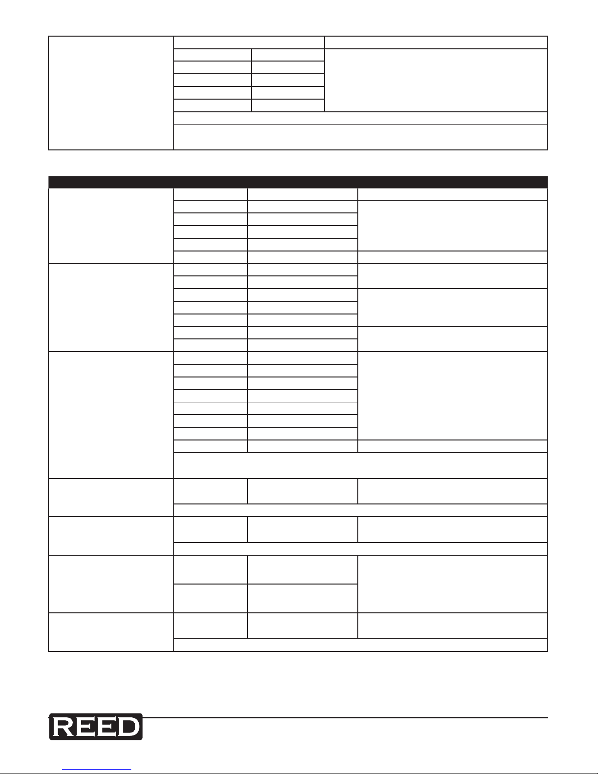
• (+ digits) – This is the accuracy of the analog to digital converter
Enclosure: Double molded, waterproof
Shock (Drop Test): 6.5 feet (2 meters)
Diode Test: Test current of 0.9mA maximum, open circuit
voltage 2.8V DC typical
Continuity Check: Audible signal will sound if the resistance is less
than 35Ω (approx.), test current <0.35mA
Peak: Captures peaks >1ms
Temperature Sensor: Requires type K thermocouple
Input Impedance: >10MΩ VDC & >3MΩ VAC
AC Response: True RMS
AC True RMS: The term stands for “Root-Mean-Square”,
which represents the method of calculation of
the voltage or current value.
Average responding multimeters are calibrated
to read correctly only on sine waves and they
will read inaccurately on non-sine wave or
distorted signals. True rms meters read
accurately on either type of signal
ACV Bandwidth: 50Hz to 1000Hz
Crest Factor: ≤3 at full scale up to 500V, decreasing linearly
to ≤1.5 at 1000V
Display: 40,000 count backlit liquid crystal with bargraph
Overrange indication: “OL” is displayed
Auto Power Off: 15 minutes (approximately) with disable feature
Polarity: Automatic (no indication for positive); Minus (-)
sign for negative
Measurement Rate: 2 times per second, nominal
Low Battery Indication: is displayed if battery voltage drops below
operating voltage
Battery: One 9 volt (NEDA 1604) battery
Fuses: mA, µA ranges; 0.5A/1000V ceramic fast blow
A range; 10A/1000V ceramic fast blow
Operating Temperature: 41ºF to 104ºF (5ºC to 40ºC)
Storage Temperature: -4ºF to 140ºF (-20ºC to 60ºC)
Operating Humidity: Max 80% up to 87ºF (31ºC) decreasing linearly
to 50% at 104ºF (40ºC)

reedinstruments
www com
8
Pantone 534 Blue
Pantone 123 Yellow
Pantone 485 Red
Pantone 123 Yellow
Pantone 534 Blue
Black Rich Black -
20/20/20/100
Blue - 100/80/30/5
Yellow - 0/27/100/0
Red - 10/100/100/5
Yellow - 0/27/100/0
Blue - 100/80/30/5
Only if you REALLY need them:
Pantone 534 Blue - 100/80/30/5
Pantone 485 Red - 10/100/100/5
Pantone 123 Yellow - 0/27/100/
Storage Humidity: <80%
Operating Altitude: 7000ft. (2000 meters) maximum
Weight: 0.753lb (342g) includind holster
Size : 7.36” x 3.2” x 2.0” (187 x 81 x 50mm)
(includes holster)
Safety: This meter is intended for origin of installation
use and protected, against the users, by double
insulation per EN61010-1 and IEC61010-1 2nd
Edition (2001) to Category IV 600V & Category
III 1000V; Pollution Degree 2. The meter
also meets UL 61010-1, 2nd Edition (2004),
CAN/CSA C22.2 No. 61010-1 2nd Edition
(2004), & UL 61010B-2-031, 1st Edition (2003)
Instrument Description
1 - 40,000 count LCD display
2 - REL button
3 - RANGE button
4 - MODE button
5 - Function switch
6 - mA, µA and 10A input jacks
7 - COM input jack
8 - Positive input jack
9 - HOLD and (Backlight) button
10 - PEAK button
11 - MAX/MIN button
Note: Tilt stand and battery compartment are on back of unit.

reedinstruments
www com
9
Pantone 534 Blue
Pantone 123 Yellow
Pantone 485 Red
Pantone 123 Yellow
Pantone 534 Blue
Black Rich Black -
20/20/20/100
Blue - 100/80/30/5
Yellow - 0/27/100/0
Red - 10/100/100/5
Yellow - 0/27/100/0
Blue - 100/80/30/5
Only if you REALLY need them:
Pantone 534 Blue - 100/80/30/5
Pantone 485 Red - 10/100/100/5
Pantone 123 Yellow - 0/27/100/
Display Description
Continuity
Diode test
Battery status
n nano (10-9) (capacitance)
µ micro (10-6) (amps, cap)
m milli (10-3) (volts, amps)
A Amps
k kilo (103) (ohms)
F Farads (capacitance)
M mega (106) (ohms)
Ω Ohms
PEAK Peak Hold
Hz Hertz (frequency)
V Volts
% Percent (duty ratio)
REL Relative
AC Alternating current
AUTO Autoranging
DC Direct current
HOLD Display hold
ºF Degrees Fahrenheit
ºC Degrees Centigrade
MAX Maximum
MIN Minimum

reedinstruments
www com
10
Pantone 534 Blue
Pantone 123 Yellow
Pantone 485 Red
Pantone 123 Yellow
Pantone 534 Blue
Black Rich Black -
20/20/20/100
Blue - 100/80/30/5
Yellow - 0/27/100/0
Red - 10/100/100/5
Yellow - 0/27/100/0
Blue - 100/80/30/5
Only if you REALLY need them:
Pantone 534 Blue - 100/80/30/5
Pantone 485 Red - 10/100/100/5
Pantone 123 Yellow - 0/27/100/
Operating Instructions
WARNING: Risk of electrocution. High-voltage circuits, both AC and DC,
are very dangerous and should be measured with great care.
1. ALWAYS turn the function switch to the OFF position when the meter is
not in use
2. If “OL” appears in the display during a measurement, the value exceeds
the range you have selected. Change to a higher range
DC Voltage Measurement
CAUTION: Do not measure DC voltages if a motor on the circuit is
being switched ON or OFF. Large voltage surges may occur that can
damage the meter.
1. Set the function switch to the green VDC position
2. Insert the black test lead banana plug into the negative COM jack
Insert the red test lead banana plug into the positive V jack
3. Touch the black test probe tip to the negative side of the circuit
Touch the red test probe tip to the positive side of the circuit
4. Read the voltage in the display
AC Voltage (Frequency, Duty Cycle) Measurement
WARNING: Risk of Electrocution. The probe tips may not be long
enough to contact the live parts inside some 240V outlets for
appliances because the contacts are recessed deep in the outlets.
As a result, the reading may show 0 volts when the outlet actually has
voltage on it. Make sure the probe tips are touching the metal contacts
inside the outlet before assuming that no voltage is present.
CAUTION: Do not measure AC voltages if a motor on the circuit is
being switched ON or OFF. Large voltage surges may occur that can
damage the meter.
continued ...

reedinstruments
www com
11
Pantone 534 Blue
Pantone 123 Yellow
Pantone 485 Red
Pantone 123 Yellow
Pantone 534 Blue
Black Rich Black -
20/20/20/100
Blue - 100/80/30/5
Yellow - 0/27/100/0
Red - 10/100/100/5
Yellow - 0/27/100/0
Blue - 100/80/30/5
Only if you REALLY need them:
Pantone 534 Blue - 100/80/30/5
Pantone 485 Red - 10/100/100/5
Pantone 123 Yellow - 0/27/100/
1. Set the function switch to the green VAC/Hz/% position
2. Insert the black test lead banana plug into the negative COM jack
Insert red test lead banana plug into the positive V jack
3. Touch the black test probe tip to the neutral side of the circuit
Touch the red test probe tip to the “hot” side of the circuit
4. Read the voltage in the display
5. Press the MODE button to indicate “Hz”
6. Read the frequency in the display.
7. Press the MODE button again to indicate “%”
8. Read the % of duty cycle in the display
DC Current Measurement
CAUTION: Do not make 20A current measurements for longer than
30 seconds. Exceeding 30 seconds may cause damage to the meter
and/or the test leads.
1. Insert the black test lead banana plug into the negative COM jack
2. For current measurements up to 4000µA DC, set the function switch to
the yellow µA position and insert the red test lead banana plug into the
µA/mA jack
3. For current measurements up to 400mA DC, set the function switch to
the yellow mA position and insert the red test lead banana plug into the
µA/mA jack
4. For current measurements up to 20A DC, set the function switch to the
yellow 10A/HZ/% position and insert the red test lead banana plug into
the 10A jack
5. Press the MODE button to indicate “DC” on the display
6. Remove power from the circuit under test, then open up the circuit at
the point where you wish to measure current
7. Touch the black test probe tip to the negative side of the circuit.
Touch the red test probe tip to the positive side of the circuit
8. Apply power to the circuit
9. Read the current in the display
continued ...

reedinstruments
www com
12
Pantone 534 Blue
Pantone 123 Yellow
Pantone 485 Red
Pantone 123 Yellow
Pantone 534 Blue
Black Rich Black -
20/20/20/100
Blue - 100/80/30/5
Yellow - 0/27/100/0
Red - 10/100/100/5
Yellow - 0/27/100/0
Blue - 100/80/30/5
Only if you REALLY need them:
Pantone 534 Blue - 100/80/30/5
Pantone 485 Red - 10/100/100/5
Pantone 123 Yellow - 0/27/100/
AC Current (Frequency, Duty Cycle) Measurement
CAUTION: Do not make 20A current measurements for longer than
30 seconds. Exceeding 30 seconds may cause damage to the meter
and/or the test leads.
1. Insert the black test lead banana plug into the negative COM jack
2. For current measurements up to 4000µA AC, set the function switch
to the yellow µA position and insert the red test lead banana plug
into the µA/mA jack
3. For current measurements up to 400mA AC, set the function switch
to the yellow mA position and insert the red test lead banana plug
into the µA/mA jack
4. For current measurements up to 20A AC, set the function switch to
the yellow 10A/HZ/% position and insert the red test lead banana
plug into the 10A jack
5. Press the MODE button to indicate “AC” on the display
6. Remove power from the circuit under test, then open up the circuit at
the point where you wish to measure current
7. Touch the black test probe tip to the neutral side of the circuit
Touch the red test probe tip to the “hot” side of the circuit
8. Apply power to the circuit
9. Read the current in the display
10. Press and hold the MODE button to indicate “Hz”
11. Read the frequency in the display
12. Momentarily press the MODE button again to indicate “%”
13. Read the % duty cycle in the display
14. Press and hold the MODE button to return to current measurement
continued ...

reedinstruments
www com
13
Pantone 534 Blue
Pantone 123 Yellow
Pantone 485 Red
Pantone 123 Yellow
Pantone 534 Blue
Black Rich Black -
20/20/20/100
Blue - 100/80/30/5
Yellow - 0/27/100/0
Red - 10/100/100/5
Yellow - 0/27/100/0
Blue - 100/80/30/5
Only if you REALLY need them:
Pantone 534 Blue - 100/80/30/5
Pantone 485 Red - 10/100/100/5
Pantone 123 Yellow - 0/27/100/
Resistance Measurement
WARNING: To avoid electric shock, disconnect power to the unit
under test and discharge all capacitors before taking any resistance
measurements. Remove the batteries and unplug the line cords.
1. Set the function switch to the green Ω CAP position
2. Insert the black test lead banana plug into the negative COM jack
Insert the red test lead banana plug into the positive Ω jack
3. Press the MODE button to indicate “Ω” on the display
4. Touch the test probe tips across the circuit or part under test. It is best
to disconnect one side of the part under test so the rest of the circuit
will not interfere with the resistance reading
5. Read the resistance in the display
Continuity Check
WARNING: To avoid electric shock, never measure continuity on
circuits or wires that have voltage on them.
1. Set the function switch to the green Ω CAP position
2. Insert the black lead banana plug into the negative COM jack. Insert the
red test lead banana plug into the positive Ω jack
3. Press the MODE button to indicate and Ω on the display
4. Touch the test probe tips to the circuit or wire you wish to check
5. If the resistance is less than approximately 35Ω, the audible signal will
sound. If the circuit is open, the display will indicate “OL”
Diode Test
1. Set the function switch to the green Ω CAP position
2. Insert the black test lead banana plug into the negative COM jack and
the red test lead banana plug into the positive V jack
3. Press the MODE button to indicate and V on the display
4. Touch the test probes to the diode under test. Forward voltage will
typically indicate 0.400 to 0.700V. Reverse voltage will indicate “OL”.
Shorted devices will indicate near 0V and an open device will indicate
OL in both polarities
continued ...

reedinstruments
www com
14
Pantone 534 Blue
Pantone 123 Yellow
Pantone 485 Red
Pantone 123 Yellow
Pantone 534 Blue
Black Rich Black -
20/20/20/100
Blue - 100/80/30/5
Yellow - 0/27/100/0
Red - 10/100/100/5
Yellow - 0/27/100/0
Blue - 100/80/30/5
Only if you REALLY need them:
Pantone 534 Blue - 100/80/30/5
Pantone 485 Red - 10/100/100/5
Pantone 123 Yellow - 0/27/100/
Temperature Measurement
1. Set the function switch to the green Temp position
2. Insert the Temperature Probe into the input jacks, making sure
to observe the correct polarity
3. Press the MODE button to indicate ºF or ºC
4. Touch the Temperature Probe head to the part whose temperature you
wish to measure. Keep the probe touching the part under test until the
reading stabilizes (about 30 seconds)
5. Read the temperature in the display
Note: The temperature probe is tted with a type K mini connector.
A mini connector to banana connector adaptor is supplied for
connection to the input banana jacks.
Capacitance Measurement
WARNING: To avoid electric shock, disconnect power to the unit
under test and discharge all capacitors before taking any capacitance
measurements. Remove the batteries and unplug the line cords.
1. Set the rotary function switch to the green Ω CAP
2. Insert the black test lead banana plug into the negative COM jack.
Insert the red test lead banana plug into the positive V jack
3. Press the MODE button to indicate F
4. Touch the test leads to the capacitor to be tested
5. Read the capacitance value in the display
Frequency (Duty Cycle) Measurement (Electronic)
1. Set the rotary function switch to the green Hz/% position
2. Insert the black lead banana plug into the negative COM jack and the
red test lead banana plug into the positive Hz jack
3. Touch the test probe tips to the circuit under test
4. Read the frequency on the display
5. Press the MODE button to indicate “%”
6. Read the % duty cycle in the display

reedinstruments
www com
15
Pantone 534 Blue
Pantone 123 Yellow
Pantone 485 Red
Pantone 123 Yellow
Pantone 534 Blue
Black Rich Black -
20/20/20/100
Blue - 100/80/30/5
Yellow - 0/27/100/0
Red - 10/100/100/5
Yellow - 0/27/100/0
Blue - 100/80/30/5
Only if you REALLY need them:
Pantone 534 Blue - 100/80/30/5
Pantone 485 Red - 10/100/100/5
Pantone 123 Yellow - 0/27/100/
% 4 – 20mA Measurement
1. Set up and connect as described for DC mA measurements
2. Set the rotary function switch to the 4-20mA% position
3. The meter will display loop current as a % with 0mA=-25%, 4mA=0%,
20mA=100%, and 24mA=125%
Autoranging/Manual Range Selection
When the meter is rst turned on, it automatically goes into AutoRanging.
This automatically selects the best range for the measurements being
made and is generally the best mode for most measurements.
For measurement situations requiring that a range be manually selected,
perform the following:
1. Press the RANGE key. The “AUTO” display indicator will turn off
2. Press the RANGE key to step through the available ranges until you
select the range you want
3. To exit the Manual Ranging mode and return to Autoranging, press and
hold the RANGE key for 2 seconds
Note: Manual ranging does not apply for the Temperature functions.
Max/Min
1. Press the MAX/MIN key to activate the MAX/MIN recording mode.
The display icon “MAX” will appear. The meter will display and hold the
maximum reading and will update only when a new “max” occurs
2. Press the MAX/MIN key again and the display icon “MIN” will appear.
The meter will display and hold the minimum reading and will update
only when a new “min” occurs
3. To exit MAX/MIN mode press and hold the MAX/MIN key for 2 seconds
continued ...

reedinstruments
www com
16
Pantone 534 Blue
Pantone 123 Yellow
Pantone 485 Red
Pantone 123 Yellow
Pantone 534 Blue
Black Rich Black -
20/20/20/100
Blue - 100/80/30/5
Yellow - 0/27/100/0
Red - 10/100/100/5
Yellow - 0/27/100/0
Blue - 100/80/30/5
Only if you REALLY need them:
Pantone 534 Blue - 100/80/30/5
Pantone 485 Red - 10/100/100/5
Pantone 123 Yellow - 0/27/100/
Relative Mode
The relative measurement feature allows you to make measurements
relative to a stored reference value. A reference voltage, current, etc.
can be stored and measurements made in comparison to that value.
The displayed value is the difference between the reference value and the
measured value.
Note: Relative mode does not operate in the 4-20mA function.
1. Perform the measurement as described in the operating instructions
2. Press the REL button to store the reading in the display and the “REL”
indicator will appear on the display
3. The display will now indicate the difference between the stored value
and the measured value
4. Press the REL button to exit the relative mode
Display Backlight
Press the HOLD/ key for >1 second to turn the backlight on.
The backlight will automatically turn off after 10 seconds.
Hold
The hold function freezes the reading in the display. Press the HOLD key
momentarily to activate or to exit the HOLD function.
Peak Hold
The Peak Hold function captures the peak AC or DC voltage or current.
The meter can capture negative or positive peaks as fast as 1 millisecond
in duration. Momentarily press the PEAK button, “PEAK” and “MAX” will
display. The meter will update the dispay each time a higher positive peak
occurs. Press the PEAK button again, “MIN” will display. The meter will
update the dispay each time a lower negative peak occurs. Press and
hold the PEAK button for more than 1 second to exit PEAK Hold mode.
Auto Power Off feature will be disabled automatically in this mode.

reedinstruments
www com
17
Pantone 534 Blue
Pantone 123 Yellow
Pantone 485 Red
Pantone 123 Yellow
Pantone 534 Blue
Black Rich Black -
20/20/20/100
Blue - 100/80/30/5
Yellow - 0/27/100/0
Red - 10/100/100/5
Yellow - 0/27/100/0
Blue - 100/80/30/5
Only if you REALLY need them:
Pantone 534 Blue - 100/80/30/5
Pantone 485 Red - 10/100/100/5
Pantone 123 Yellow - 0/27/100/
Low Battery Indication
With a fresh battery installed, the battery icon with four lines above it will
be displayed in the lower right corner of the LCD. The lines will disappear
as the battery is used. When the icon appears alone in the display, the
battery should be replaced.
Auto Power Off
The auto off feature will turn the meter off after 15 minutes. To disable the
auto power off feature, hold down the MODE button and turn the meter
on. “APO d” will appear in the display. Turn the meter off and then on
agaivn to re-enable the auto power off feature.
Maintenance
WARNING: To avoid electric shock, disconnect the test leads from
any source of voltage before removing the back cover or the battery
or fuse covers.
WARNING: To avoid electric shock, do not operate your meter
until the battery and fuse covers are in place and fastened securely.
This MultiMeter is designed to provide years of dependable service,
if the following care instructions are performed:
1. Keep the meter dry. If it gets wet, wipe it off
2. Use and store the meter in normal temperatures.
Temperature extremes can shorten the life of the electronic parts
and distort or melt plastic parts
3. Handle the meter gently and carefully. Dropping it can damage the
electronic parts or the case
4. Keep the meter clean. Wipe the case occasionally with a damp cloth.
Do not use chemicals, cleaning solvents, or detergents
5. Use only fresh batteries of the recommended size and type. Remove
old or weak batteries so they do not leak and damage the unit
6. If the meter is to be stored for a long period of time,
the batteries should be removed to prevent damage to the unit

reedinstruments
www com
18
Pantone 534 Blue
Pantone 123 Yellow
Pantone 485 Red
Pantone 123 Yellow
Pantone 534 Blue
Black Rich Black -
20/20/20/100
Blue - 100/80/30/5
Yellow - 0/27/100/0
Red - 10/100/100/5
Yellow - 0/27/100/0
Blue - 100/80/30/5
Only if you REALLY need them:
Pantone 534 Blue - 100/80/30/5
Pantone 485 Red - 10/100/100/5
Pantone 123 Yellow - 0/27/100/
Battery Installation
WARNING: To avoid electric shock, disconnect the test leads from any
source of voltage before removing the battery cover.
1. Turn power off and disconnect the test leads from the meter
2. Open the rear battery cover by removing two screws (B) using a Phillips
head screwdriver
3. Insert the battery into battery holder, observing the correct polarity
4. Put the battery cover back in place. Secure with the screws
WARNING: To avoid electric shock, do not operate the meter until the
battery cover is in place and fastened securely.
NOTE: If your meter does not work properly, check the fuses and batteries
to make sure that they are still good and that they are properly inserted.

reedinstruments
www com
19
Pantone 534 Blue
Pantone 123 Yellow
Pantone 485 Red
Pantone 123 Yellow
Pantone 534 Blue
Black Rich Black -
20/20/20/100
Blue - 100/80/30/5
Yellow - 0/27/100/0
Red - 10/100/100/5
Yellow - 0/27/100/0
Blue - 100/80/30/5
Only if you REALLY need them:
Pantone 534 Blue - 100/80/30/5
Pantone 485 Red - 10/100/100/5
Pantone 123 Yellow - 0/27/100/
Replacing The Fuses
WARNING: To avoid electric shock, disconnect the test leads from
any source of voltage before removing the meter cover.
1. Disconnect the test leads from the meter
2. Remove the protective rubber holster
3. Remove the battery cover (two “B” screws) and the battery
4. Remove the six “A” screws securing the rear cover
5. Gently remove the old fuse and install the new fuse into the holder
6. Always use a fuse of the proper size and value (0.5A/1000V fast blow
for the 400mA range [SIBA 70-172-40], 10A/1000V fast blow for the 20A
range [SIBA 50-199-06])
7. Replace and secure the rear cover, battery and battery cover
WARNING: To avoid electric shock, do not operate your meter until the
fuse cover is in place and fastened securely.
For service on this or any other REED product or information on other
REED products, contact REED Instruments at [email protected].

reedinstruments
www com
20
Pantone 534 Blue
Pantone 123 Yellow
Pantone 485 Red
Pantone 123 Yellow
Pantone 534 Blue
Black Rich Black -
20/20/20/100
Blue - 100/80/30/5
Yellow - 0/27/100/0
Red - 10/100/100/5
Yellow - 0/27/100/0
Blue - 100/80/30/5
Only if you REALLY need them:
Pantone 534 Blue - 100/80/30/5
Pantone 485 Red - 10/100/100/5
Pantone 123 Yellow - 0/27/100/
Notes _________________________________________
________________________________________________
________________________________________________
________________________________________________
________________________________________________
________________________________________________
________________________________________________
________________________________________________
________________________________________________
________________________________________________
________________________________________________
________________________________________________
________________________________________________
________________________________________________
________________________________________________
________________________________________________
________________________________________________
________________________________________________
Pantone 534 Blue
Pantone 123 Yellow
Pantone 485 Red
Pantone 123 Yellow
Pantone 534 Blue
Black Rich Black -
20/20/20/100
Blue - 100/80/30/5
Yellow - 0/27/100/0
Red - 10/100/100/5
Yellow - 0/27/100/0
Blue - 100/80/30/5
Only if you REALLY need them:
Pantone 534 Blue - 100/80/30/5
Pantone 485 Red - 10/100/100/5
Pantone 123 Yellow - 0/27/100/
Other manuals for R5010
1
Table of contents
Other REED Measuring Instrument manuals
Popular Measuring Instrument manuals by other brands

Omega
Omega DVG-64 instruction sheet

PASCO
PASCO PS-3223 Product guide

Mindray
Mindray BC-5380 Service manual

Union Instruments
Union Instruments INCA6002 Translation of the original operating instructions

Siemens
Siemens MMB3-ALD-UK installation instructions

Weidmüller
Weidmüller PRO COM DISPLAY 7S operating manual